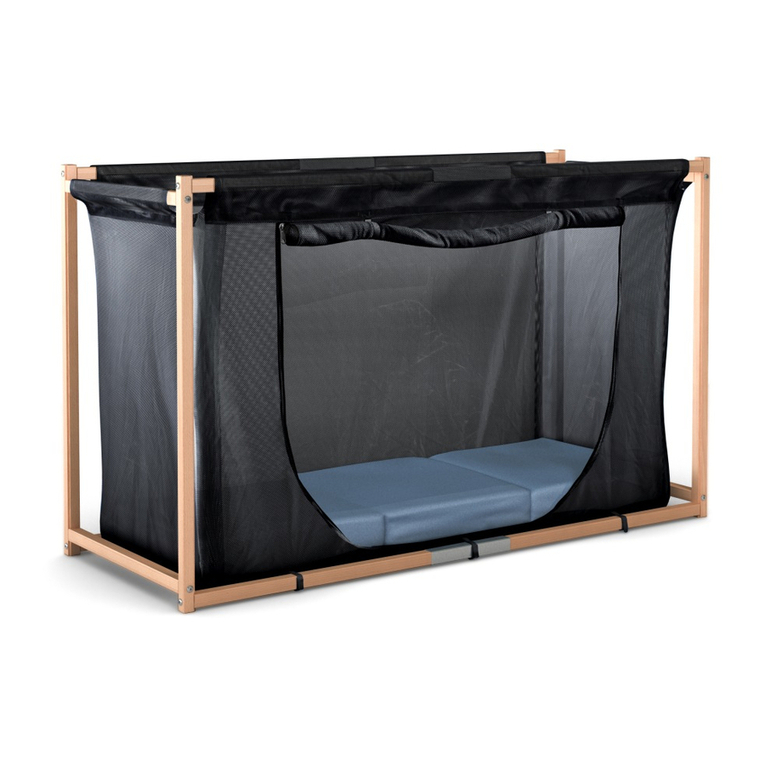
FreiStil Tischlerei LEA Quick start guide

FreiStil Tischlerei
Kroh + Kinstler GmbH & Co. KG
Ruppenkampstraße 16
D-49084 Osnabrück
Fon ++49 - 541-77974
Fax ++49 - 541-77596
E-mail info@freistil.com
Homepage: www.freistil.com
Operational Manual
Children’s Therapeutic Bed
“LEA”
Read carefully before operating!
This operational manual has to be provided to all users!
OM 2009 Lea

TABLE OF CONTENTS
1. Installation Manual (for authorized sales agents/distributors only) p
pa
ag
ge
e
1.1 Assembly of bed frame 02
1.2 Removing knobs of bed posts 02
1.3 Installation of mobile side barriers 02
1.4 Positioning of lifting scissors,
installation of bed base, fitting of grid and safety panel 03/04
1.5 Transport wheels 04
1.6 EXTRA: Adjustment of bed base by electric motor 05
1.7 EXTRA: Antitrendelenburg resting position 05
1.8 EXTRA: Removable bed posts 05
2. Operational Manual
2.1 Purpose of use 06
2.2 Important notice for operational safety 06
2.3 Warning notice 07
2.4 Lifting unit 07
2.5 Bed base 08
2.6 Manual control unit (Keyboard, functions, first fault protection) 08/08.1
2.7 Mobile side barriers 09
2.8 Transport wheels 09
2.9 Patient-lifting unit 09
2.10 Cleaning, maintenance and re-usage (list of spare parts) 10
2.11 Accessoires 10
2.12 Symbols 10
3. Technical Data
3.1 Bed frame 11
3.2 Lifting unit 11
3.3 Bed base 11
3.4 Motors 11
4. Annex (for authorizes sales agents only)
4.1 Maintenance instructions / C
CH
HE
EC
CK
K
L
LI
IS
ST
T CH1
4.1.2 Check List / Electric motor CH2
4.1.3 Check List / Lifting unit CH3
4.1.4 Check List / Bed base CH4
OM Lea – 01 4.1.5 Check List / Bed frame CH5

1
1.
.
I
IN
NS
ST
TA
AL
LL
LA
AT
TI
IO
ON
N
M
MA
AN
NU
UA
AL
L
The installation has to be carried out by trained specialized staff only. We recommend installation by
two people following these steps:
1.1 On the inner side of the bed there are stickers with
numbered arrows from 1 to 4 (pict. 1).
Assign the side panels, head- and foot-end according
to these numbers.
picture 1
According to their numbers the side panels are connected
with the head- and foot-end (pict. 2)
Push the side panels right down till they rest in
the fittings. Check whether they fit well.
p
pi
ic
ct
tu
ur
re
e
2
2
1.2 Knobs of the bed posts can be removed.
Remove screws and take off the knobs by pulling them
upwards (pict. 3).
Put them back and fix them after the four mobile side barriers
were put in.
p
pi
ic
ct
tu
ur
re
e
3
3
1.3 Insert the side barriers into the groove of the bed posts starting from top (pict. 4).
Bring them down to its lowest position by operating the lock mechanism on both sides of the
barrier at the same time (pict. 5).
p
pi
ic
ct
tu
ur
re
e
4
4
p
pi
ic
ct
tu
ur
re
e
5
5
OM Lea – 02

1.4 At the lifting scissors there is a sticker „head-end“.
Bring the lifting scissors into position according to the
sticker „head-end“ inside the bed frame.
Place the scissors of lifting unit into the bed frame (pict. 6).
Bring lifting scissors to its highest position (pict. 7).
Place the 3-pieces-bed base of the lifting unit onto the
scissors (pict. 8).
Fix bed base using the screws (M6 x 30mm) enclosed (pict. 9).
p
pi
ic
ct
tu
ur
re
e
6
6
p
pi
ic
ct
tu
ur
re
e
7
7
p
pi
ic
ct
tu
ur
re
e
8
8
p
pi
ic
ct
tu
ur
re
e
9
9
Bring the bed base down to top-level of bed frame and
line it up (pict. 10).
If necessary, loosen the screws of the metallic adapter
(connection between scissors + weight bearing rail at
side panel), line up lifting scissors and tighten screws again.
Fix lifting scissors with wood screws (6 x 40mm) p
pi
ic
ct
tu
ur
re
e
1
10
0
attached onto the weight-bearing rail (pict. 11).
Fix manual adjustment for foot-end of bed base
to the lifting scissors (pict. 12).
Check whether relief of tension is tightly fixed (pict. 13)!
picture 11 picture 12 picture 13
OM Lea - 03

Connect cable of bed base’s motor to the control unit
(only if there is an electric head-end or head- and foot-end adjustment).
The control unit is situated at the motor of lifting scissors.
Attention!
Wires must not be damaged or crushed or damaged!!!
Safety panel (pict. 14 + 15) has to be fixed with the
countersunk screws attached.
The safety panel consists of 4 x 2 pairs, picture 14
that have to be fixed as follows :
pair 1 onto the long sides next to the head-end,
pair 2 onto the middle part of the bed base,
pair 3 onto the long sides next to the foot-end,
pair 4 onto the short ends of head- and foot-end.
picture 15
Transport Wheels
Double break castor 75 x 30mm.
To lock press down foot lever,
to unlock pull it up (pict. 16).
Every time the bed had been moved into position
all castors have to be locked firmly!
OPTIONAL: EXTRA
Double break castor 100 x 30mm. picture 16
OM Lea - 04

1.6 OPTIONAL: EXTRA
Head-end electrically, foot-end manually adjustable
Port in control unit: Head-end 4
Head- and foot-end electrically adjustable.
Fit the already assembled motor for
the foot-end onto the bed base (pict. 17).
Port in control unit: lifting motor 6
motor head-end 4
motor foot-end 1
manual switch 2 picture 17
shortcut circuit plug 7
Attention!
Wires must not be damaged or crushed or damaged!!!
1.7 OPTIONAL: EXTRA
Anti-Trendelenburg resting position
For this Position there are
one 2nd Manual Control + one 2nd Control gear (pict 18).
Attention when lowering the head-end! picture 18
Danger of getting crushed at the lower
cross-bar.
After having fixed the bed panels, do fix the
strips of wood (pict. 19) attached
between side panel and bed post.
1.8 OPTIONAL: EXTRA
Removable Bed Post picture 19
TAKE OFF Unscrew the knob (pict. 20), take off the bed post.
PUT ON Place bed post onto the socket, tighten screw, check whether it is firmly fixed!
(pict. 21)
picture 20 picture 21
Manufacturer: FreiStil Tischlerei Kroh + Kinstler GmbH & Co. KG
Ruppenkampstraße 16, D-49084 Osnabrück
Fon ++49-541-77 974, Fax ++49-541-77 596
OM Lea – 05 e-mail: info@freistil.com, www.freistil.com

2. OPERATING DIRECTIONS
2.1 Purpose of use
The children’s therapeutic bed „LEA” is designed for private use at home as well as for domestic
care. It’s medical objective is to provide the alleviation, treatment and surveillance of illness and
injuries by the various resting positions for the child. The multifunctional options increase the benefit.
For safety reasons the bed is not for use for medical treatments using electricity, since this model is
not conceived as a hospital bed. It is licensed for one (1) person only and the maximum patient
weight (see specification label) must not be exceeded. The bed is for indoor use only and has to be
protected from high humidity. All technical functions can be controlled by a lockable IPX4-manual
control unit with magnetic key.
All components of the bed are only permitted for use according to its intended purpose.
Overload may cause damage and is not permitted.
2.2 Important notes for operational safety
I. Set-up and initial operation have to be carried out by authorized distributors. A functional test
has to be carried out prior to handing the bed over to the customer. Attention has to be paid
to: the smooth running of all functions, the installation of power supply according to the
regulations, the firm installation of the lifting unit within the bed frame as well as the fitting of
the bed base to the lifting unit. This also applies to further operation of the children’s
therapeutic bed.
Improper installation of mains connection may cause serious damage (electric shock)
to people.
II. The maximum weight of the patient must not exceed 100 kg. People of any age with limited
perceptive faculty may operate the system under supervision only.
III. The lowest position of the bed base is the safest position and should be used in any case,
unless therapy + nursing require a different position.
After treatment always return the lifting unit to its lowest position.
IV. While moving the lifting unit make sure that no parts of the body
get in or under the moving elements. DANGER OF BEEING
CRUSHED!
V. The therapeutic bed for children „LEA” is designed for dry rooms
and must be used and stored in such rooms only.
The system may only be operated by state-of-the-art 230 Volt plugs. Cables + plugs have to
be dry. Make sure that cables are not crushed or do not rub against anything. Pay attention to
the proper laying and fixing of all cables at the positions advised.
VI. To avoid overload and defects of the electric engine the power-on time must not exceed a
maximum time of 2 minutes.
The electric adjustment for the head-end or the head- and foot-end must only be used
for lifting/ lowering the upper body or legs of the patient (patient must be in proper
position!). Overload causes damage and is not permitted!!!
Overloading the mechanical components causes damage and therefore is not permitted
(see Operational Manual TOP 2.3 + 2.4 as well as specification label).
VII. Liability for any kind of damages and injuries is explicitly excluded in case of misuse, improper
use, wrong operation or inexpert installation/repair. Furthermore all kinds of guarantees are
also excluded in such a case.
OM Lea – 06


VIII. The electric engines of the bed may not be used in locations where inflammable gases or
fumes occur.
IX. The therapeutic bed „LEA” may only be operated and maintained by using original
accessories and original spare parts.
X. Operational malfunction must be reported immediately to the authorized distributor.
Stop using the equipment and disconnect the mains, especially when electrical or
mechanical parts are damaged.
2.3 Warnings
I. Transport of the patient is only permitted in the lowest, horizontal position of the lifting unit.
II. While the patient is unattended the lifting unit has to be on its lowest position. The side barriers
have to be in highest position and firmly locked.
III. Do not leave things behind in the bed that could be used for climbing up or can lead to
suffocation or strangulation.
IV. The lifting unit must only be operated by people briefed or by the nursing staff.
The patient must not operate the bed themselves.
While the patient is unattended all functions have to be locked.
V. The patient’s clinical condition may increase the danger of being squeezed in.
VI. DANGER OF BEING SQUEEZED IN when opening/closing the side barriers.
The mobile side barriers must only be opened + closed while the patient is
under supervision.
VII. The therapeutic bed „LEA” must only be used upon even, horizontal and
solid ground.
VIII. Use bed in dry rooms only.
IX. Do not place the bed near open fire or other strong heat sources (i.e. electric radiator,
gas heater etc.).
X. Maximum patient is 100 kg.
Safe working load is 170 kg, incl. equipment.
Electric adjustment of head-end or head- and foot-end (Extra) must only be used for
lifting/lowering the upper body or the legs (Make sure the patient is in appropriate position).
2.4 Lifting unit
The lifting unit serves the purpose of lifting the bed base up and down by an electric motor.
Maximum patient weight: 100 kg.
Safe working load: 170 kg, incl. equipment.
Overload causes damage and is not permitted.
OM Lea – 07

2.5 Bed base
Standard equipment: manually adjustable head- and foot-end.
A. Optional: The head-end is adjustable by an electric motor (EXTRA).
The adjustment of the foot-end is always done manually
by means of a grid.
B. Optional: The head- and foot-end are adjustable by
an electric motor (EXTRA).
It is not recommended to move the head- and foot-end
to the highest position at the same time.
The patient may be cramped in and
feel uncomfortable.
picture 22
In case the head-end got stuck in it’s position due to power cut or fault of the motor moving
the bed base (Extra) you have the opportunity to bring down the head-end manually. Follow
according these steps:
Fold up the head-end and hold it with one hand. With the other hand remove
the safety ring (pict. 22) out of the bolt at the bed base motor. After that pull the bolt
out of the metal plate. The head-end can be lowered now. But it is not possible
to adjust the head- end by the electric motor. In order to restore the function you
have to fold up the head-end as far as you can, pierce the bolt through the
man-made liner of the motor + the metal plate. After that put the safety ring back
in place into the bolt.
2.6 Manual Control Unit
All electric functions can be operated by the manual control unit. Options of adjusting
height and positions of the head-end are marked by respective symbols. By gently
pressing the respective button the system moves to the required position.
During operation make sure that the cable of the manual control unit is not squeezed in.
To avoid malfunction do place the manual control unit onto the bed frame,
when not in use. The key pad should be facing away from the bed.
Keep the manual control unit away from magnetic objects and strong magnetic
fields (>= 1,0 metre). The integrated lock-system can be activated or deactivated.
By passing the magnetic key over the defined field of the manual control,
-
the functions of the control can be activated (green LED flashes) = functions are available
-
the functions of the control can be deactivated (green LED turns off) = functions are
completely blocked.
The magnetic key is a safety element preventing unauthorized use of the manual control unit.
Therefore it always has to be kept separate from the manual control.
On the following page you will find details on keys + diagram of functions of the manual
control unit: IPROXX SE / SE+
OM Lea - 08

Keys and Functions
Example: Manual control unit IPROXX SE with 4 buttons for movement
Diagram of Functions
Functions-LED LED shows green light when the button is pressed
Display of First Fault Protection
First Fault Protection
There is a fault /first fault in the integrated lock-system, if
- the LED-mode does show green light when locked;
-the LED-mode does not show green light when unlocked;
-there is a difference in intensity of light (LED-mode) noticeable while one of the buttons for
movement is pressed in locked state (LED-mode switched on).
After lockage: Press one button after the other to make sure all are locked safely.
OM LEA – 08.1
Putting into operation
Connect the manual switch with the Dewert-System
The manual control changes to mode 1 automatically.
Mode 1
The manual control is absolutely blocked.
LED Mode does not shine.
Mode 2
Customers specific functions for adjustment are
available. LED mode shows green light.
1x stroke across symbol ‘magnetic lock’
with
the magnetic side of magnetic key.
Off
green
1x stroke across symbol ‚magnetic lock’
with the magnetic side of magnetic key.
LED Functio
ns
O Head-end up ▲ ▼down
O Lifting Unit up ▲ ▼down
LED Mode
Symbol Magnetic Key (control area)
Magnetic side
Magnetic key

2.7 Side Barriers
In order to lower or to lift the side barrier the two locks have to be handled at the same time.
Place your forefinger in the finger hole and your middle- and ring finger into the grip shell
underneath (pict. 23).
Push your forefinger towards the centre of the bed in order
to open the lock. After that no further pressure on the lock
is necessary. The side barrier will glide down easily to its
next stop. picture 23
2.8 Transport wheels
Double brake castor, 75 x 30mm.
To lock press down foot lever,
to unlock pull foot lever up (pict. 24).
E
Ev
ve
er
ry
y
t
ti
im
me
e
t
th
he
e
b
be
ed
d
h
ha
ad
d
b
be
ee
en
n
m
mo
ov
ve
ed
d
i
in
nt
to
o
p
po
os
si
it
ti
io
on
ns
s
a
a
l
l
l
l
c
ca
as
st
to
or
rs
s
have to be locked firmly!
OPTONAL: EXTRA
Double brake castor, 100 x 30mm.
picture 24
2.9.1 Patient-Lifting Unit
For the children’s therapeutic bed „LEA”the patient-lifting units
„ARNOLD“ + „JAMES“ of the manufacturer REBOTEC, D-49610 Quakenbrück
have to be used exclusively.
Free space required underneath the bed: max. 110 mm resp. 90 mm.
OM Lea – 09

2.10 Cleaning, Maintenance and Re-use
The polished surface ensures easy cleaning and disinfection. Neither the electric equipment nor
the bed frame should be cleaned by high pressure cleaning equipment. For cleaning use a
damp cloth and a little neutral soap, dry afterwards using a dry cloth.
Disinfection of the bed with a commercially available disinfecting agent is possible.
Re-use is possible after proper cleaning, disinfection and maintenance.
Maintenance must be carried out by the authorized distributor. A check up on all functions
should be done prior to re-use of the bed or at the patient’s house when the bed had been on
long-term use. A 1-years period for check ups on all components is obligatory.
Spare part lists available from the manufacturer!
2.11 EXTRAS
Nursing mattress type „Grisu“, flame-retardent
Retouching pen for metal frame
Set for surface treatment of the wooden parts
2.12 Symbols
Protection class II
Use in dry rooms only
Danger of being squeezed or crushed
Important notice in Operating Directions
Application part Type B
Manufacturer: FreiStil Tischlerei Kroh + Kinstler GmbH & Co. KG
Ruppenkampstraße 16, D-49084 Osnabrück
Fon ++49-541-77 974, Fax ++49-541-77 596
email: info@freistil.com, www.freistil.com
OM Lea – 09

3. TECHNICAL DETAILS
3.1 Bed Frame
Exterior dimensions: 1.180 x 2.180 mm
980 x 1.780 mm
Interior dimensions: 1.000 x 2.000 mm
800 x 1.600 mm
Height of bed: 1.490 mm
OK mattress 750 – 1.010 mm
Hight of side barriers: 605 mm
Weight of Bed frame + Lifting unit
a
ap
pp
pr
ro
ox
x.
.
1
18
80
0
k
kg
g
Weight of:
Head- and foot-end panel 45 kg
Side panels 35 kg
Mobile side barriers, long 25 kg
Mobile side barriers, short 15 kg
Total weight of bed frame: approx. 120 kg
Mattress standard: RG35, 12 cm, approx. 5 kg
3.2 Lifting Unit (H. Kirchner Handels GmbH)
Dimensions (lenght x width x height) 130 x 71 x 22 cm
Weight approx. 25 kg
Lifting width 260 mm
Lifting capacity 230 kg
3.3 Bed base: (H. Kirchner Handels GmbH)
Dimensions 95 x 195 cm
Number of pieces 3
Weight approx. 20 Kg
Maximum patient weight 100 kg
Safe working load 170 kg
3.4 Engines: Lifting unit „Megamat“
Mains voltage / frequence 230 Volt / 50 hz
Engine voltage 24 Volt
Protective class II
Sound output < 65 dB (A)
Term of operating max. 2 min. / 18 min. OFF
Technical Details may be subject to alterations!!!
Manufacturer: FreiStil Tischlerei Kroh + Kinstler GmbH & Co. KG
Ruppenkampstraße 16, D-49084 Osnabrück
Fon ++49-541-77 974, Fax ++49-541-77 596
email: info@freistil.com, www.freistil.com
OM Lea – 11

4
4.
.
A
AN
NN
NE
EX
X
4
4.
.1
1
M
Ma
ai
in
nt
te
en
na
an
nc
ce
e
I
In
ns
st
tr
ru
uc
ct
ti
io
on
ns
s
/
/
C
CH
HE
EC
CK
K
L
LI
IS
ST
T
With this maintenance instructions we will enable you to carry out the requested safety
and technical check-ups as requested by REGULATIONS for USERS of MEDICAL
PRODUCTS, Germany (MPBetreibV). Further regulations and laws of the legislator
or professional organisations are not covered.
The instructions are structured as following:
4.1.1. General Notes
4.1.2 CHECK LIST / Electric Motors
4.1.3 CHECK LIST / Lifting Unit
4.1.4. CHECK LIST / Bed base
4.1.5 CHECK LIST / Bed frame
4
4.
.1
1.
.1
1
G
Ge
en
ne
er
ra
al
l
N
No
ot
te
es
s
- Maintenance and repair works may be carried out by qualified and authorized
personnel only.
(To entitle the personnel for repair works, the manufacturer
of the electric motor requests an individual authorisation made out by himself !)
- Maintenance
electrical equipment every 12 months
R
Re
eg
gu
ul
la
ar
r
i
in
ns
sp
pe
ec
ct
ti
io
on
n
o
of
f
t
th
he
e
e
el
le
ec
ct
tr
ri
ic
c
r
re
es
si
is
st
to
or
r
a
an
nd
d
t
th
he
e
l
le
ea
ak
ka
ag
ge
e
c
cu
ur
rr
re
en
nt
t
a
ac
cc
co
or
rd
di
in
ng
g
t
to
o
V
VD
DE
E
7
75
51
1-
-1
1,
,
u
us
si
in
ng
g
a
a
g
ga
au
ug
ge
e
m
ma
an
nu
uf
fa
ac
ct
tu
ur
re
ed
d
i
i.
.e
e.
.
b
by
y
B
Be
en
nt
tr
ro
on
n,
,
M
Me
er
rt
te
en
ns
s
o
or
r
e
eq
qu
ua
al
l.
.
Mechanical components every 12 months
Maintenance inspections may be carried out at site of installation. Further
repair works have to be carried out at suitable work stations.
- Only original spare parts are permitted. Self-made components will make
expire any liability or guarantee by the original manufacturer.
List of spare parts is available from the manufacturer.
- Alterations in the system, modifications and /or extensions require the prior
written approval by the manufacturer.
- There has to be run a complete functional test after each and every
maintenance and/or repair. Pay attention to all moving parts running without
collision in order to avoid any kind of hazards to patient and others as well as
damages to the material and the components.
- In order to enable you to document your work we enclosed provide some
CHECK-LISTS to tick off.
Further check-ups necessary, i.e. according to accident prevention rules
released by the professional association or any accident prevention association
etc. remain in force without limitation.
OM Lea – CH1

4.1.2 C
CH
HE
EC
CK
K
L
LI
IS
ST
T
/
/
E
El
le
ec
ct
tr
ri
ic
c
M
Mo
ot
to
or
rs
s
Serial Number Year of Manufacture
------------------------- -------------------------
Last Inspection Next Inspection
------------------------- -------------------------
1
1.
.
A
Ar
re
e
a
al
ll
l
c
ca
ab
bl
le
es
s
f
fu
un
nc
ct
ti
io
on
ni
in
ng
g
p
pr
ro
op
pe
er
rl
ly
y?
? yes no
Check, if there is any damage.
(bruises, cracks, disruption, knots etc.) -------- --------
2
2.
.
S
St
tr
ra
ai
in
n
r
re
el
li
ie
ef
f
w
wo
or
rk
ki
in
ng
g?
?
Check on motor and lifting unit. -------- --------
3
3.
.
A
Ar
re
e
c
ca
ab
bl
le
es
s
c
co
or
rr
re
ec
ct
tl
ly
y
l
la
ai
id
d?
?
Check on cable run. -------- --------
4
4.
.
A
An
ny
y
t
tr
ra
ac
ce
es
s
o
of
f
l
li
iq
qu
ui
id
ds
s?
?
Check if liquids reached the motor. -------- --------
5
5.
.
C
Cr
ra
an
nk
kc
ca
as
se
e
u
un
nd
da
am
ma
ag
ge
ed
d?
?
Check whether there are any cracks. -------- --------
6
6.
.
M
Ma
an
nu
ua
al
l
s
sw
wi
it
tc
ch
h
u
un
nd
da
am
ma
ag
ge
ed
d?
?
Check if it shows any cracks. -------- --------
7
7.
.
E
El
le
ec
ct
tr
ri
ic
c
c
co
on
nt
tr
ro
ol
l
u
un
ni
it
t
o
ok
ka
ay
y?
?
Check connections. -------- -------
8
8.
.
I
Is
s
t
th
he
e
l
li
if
ft
ti
in
ng
g
m
mo
ot
to
or
r
r
ru
un
nn
ni
in
ng
g
s
sm
mo
oo
ot
th
hl
ly
y?
?
Check all positions.
(Does it stop accordingly at the final positions?) -------- --------
9
9.
.
I
Is
s
t
th
he
e
m
mo
ot
to
or
r
m
mo
ov
vi
in
ng
g
t
th
he
e
b
be
ed
d
b
ba
as
se
e
r
ru
un
nn
ni
in
ng
g
s
sm
mo
oo
ot
th
hl
ly
y?
?
Check all positions.
(Does it stop accordingly at the final positions?) -------- --------
Date Inspected by
------------------------------ ------------------------------
Stamp / Signature
---------------------------------------------------------------------------
OM Lea – CH2

4
4.
.1
1.
.3
3
C
CH
HE
EC
CK
K-
-L
LI
IS
ST
T
/
/
L
Li
if
ft
ti
in
ng
g
S
Sc
ci
is
ss
so
or
rs
s
Serial Number Year of Manufacture
------------------------- -------------------------
Last Inspection Next Inspection
------------------------- -------------------------
1
1.
.
M
Me
et
ta
al
l
b
bo
ol
lt
ts
s
+
+
m
ma
an
n-
-m
ma
ad
de
e
l
li
in
ne
er
rs
s
o
ok
ka
ay
y?
?
yes no
Check the proper fitting of the resting liners and whether they
have no damage. -------- --------
2
2.
.
F
Fr
ra
am
me
e
a
an
nd
d
l
li
if
ft
ti
in
ng
g
s
sc
ci
is
ss
so
or
rs
s
o
ok
ka
ay
y?
?
Check if their are any signs of corrosion or distortion. -------- --------
3
3.
.
G
Gl
li
id
di
in
ng
g
s
st
to
on
ne
es
s
o
ok
ka
ay
y?
?
Check whether the gliding stones inside the U-profiled rails
show any sign of wear. -------- --------
4
4.
.
A
Ad
da
ap
pt
te
er
r
a
at
t
b
be
ed
d
b
ba
as
se
e
o
ok
ka
ay
y?
?
Check the securing screws. -------- --------
I
In
n
a
a
b
be
ed
d
w
wi
it
th
h
r
re
eg
gu
ul
la
ar
r
u
us
se
e
w
we
e
r
re
ec
co
om
mm
me
en
nd
d
t
to
o
r
re
ep
pl
la
ac
ce
e
a
al
ll
l
b
bo
ol
lt
ts
s
a
an
nd
d
r
re
es
st
ti
in
ng
g
l
li
in
ne
er
rs
s
a
af
ft
te
er
r
3
3
y
ye
ea
ar
rs
s
o
op
pe
er
ra
at
ti
in
ng
g.
.
Date Inspected by
------------------------------ ------------------------------
Stamp / Signature
---------------------------------------------------------------------------
OM Lea – CH3

4
4.
.1
1.
.4
4
C
CH
HE
EC
CK
K-
-L
LI
IS
ST
T
/
/
B
Be
ed
d
B
Ba
as
se
e
Serial Number Year of manufacture
------------------------- -------------------------
Last Inspection Next Inspection
------------------------- -------------------------
1
1.
.
H
He
ei
ig
gh
ht
t
t
to
ol
le
er
ra
an
nc
ce
e
o
ok
ka
ay
y?
?
yes no
Check if the bed base is in horizontal state in every position
possible. -------- --------
2
2.
.
C
Co
on
nn
ne
ec
ct
ti
io
on
n
b
be
et
tw
we
ee
en
n
l
li
if
ft
ti
in
ng
g
s
sc
ci
is
ss
so
or
rs
s
a
an
nd
d
b
be
ed
d
b
ba
as
se
e
o
ok
ka
ay
y?
?
Check the two ball bearing sockets and their four screws. -------- --------
3
3.
.
A
Ad
dj
ju
us
st
tm
me
en
nt
t
o
of
f
h
he
ea
ad
d-
-e
en
nd
d
w
wo
or
rk
ki
in
ng
g?
?
Check on the mechanical emergency function. -------- --------
4
4.
.
A
Ad
dj
ju
us
st
tm
me
en
nt
t
o
of
f
f
fo
oo
ot
t-
-e
en
nd
d
w
wo
or
rk
ki
in
ng
g?
?
Check on the grid. -------- --------
5
5.
.
B
Be
ed
d
b
ba
as
se
e
o
ok
ka
ay
y?
?
Check the function of the bed base and if there is any damage. -------- --------
6
6.
.
S
Sa
af
fe
e
d
di
is
st
ta
an
nc
ce
e
b
be
et
tw
we
ee
en
n
b
be
ed
d
b
ba
as
se
e
a
an
nd
d
b
be
ed
d
f
fr
ra
am
me
e
s
su
uf
ff
fi
ic
ci
ie
en
nt
t?
?
Check that the distance is the same everywhere. -------- --------
7
7.
.
A
Al
ll
l
s
sc
cr
re
ew
ws
s
t
ti
ig
gh
ht
t?
?
Check quantity of screws and whether they are firmly fixed. -------- -------
Date Inspected by
------------------------------ ------------------------------
Stamp / Signature
---------------------------------------------------------------------------
OM Lea – CH4

4
4.
.1
1.
.5
5
C
CH
HE
EC
CK
K-
-L
LI
IS
ST
T
/
/
B
Be
ed
d
F
Fr
ra
am
me
e
Serial Number Year of manufacture
------------------------- -------------------------
Last Inspection Next Inspection
------------------------- -------------------------
1
1.
.
W
Wo
oo
od
de
en
n
p
pa
ar
rt
ts
s
o
ok
ka
ay
y?
?
yes no
Check wooden frame and décor. Do they show any cracks or
distortion. -------- --------
2
2.
.
C
Co
on
nn
ne
ec
ct
ti
io
on
ns
s
o
ok
ka
ay
y
o
of
f
s
si
id
de
e
p
pa
an
ne
el
ls
s,
,
r
re
ea
ar
r
p
pa
an
ne
el
l
+
+
d
do
oo
or
rs
s
a
an
nd
d
h
he
ea
ad
d-
-/
/f
fo
oo
ot
t-
-e
en
nd
d?
?
Check on all countersunk screws. -------- --------
3
3.
.
W
Wo
oo
od
de
en
n
b
ba
ar
rs
s
a
an
nd
d
„
„S
SP
PE
EC
CT
TA
AR
R®
®“
“
o
ok
ka
ay
y?
?
Check especially the SPECTAR® screens for any damage. -------- --------
4
4.
.
A
Al
ll
l
l
lo
oc
ck
ks
s
o
of
f
d
do
oo
or
rs
s
o
ok
ka
ay
y?
?
Check whether all locks are easy to move. -------- --------
5
5.
.
T
Tr
ra
an
ns
sp
po
or
rt
t
w
wh
he
ee
el
ls
s
o
ok
ka
ay
y?
?
Check on function and whether they are fixed tightly. -------- --------
Date Inspected by
------------------------------ ------------------------------
Stamp / Signature
---------------------------------------------------------------------------
OM Lea – CH5
Table of contents
Other FreiStil Tischlerei Indoor Furnishing manuals

FreiStil Tischlerei
FreiStil Tischlerei GULLIVER User manual

FreiStil Tischlerei
FreiStil Tischlerei LISA synchro 102 User manual

FreiStil Tischlerei
FreiStil Tischlerei LEA Standard User manual

FreiStil Tischlerei
FreiStil Tischlerei LUKAS 136 User manual

FreiStil Tischlerei
FreiStil Tischlerei JEREMIA User manual
Popular Indoor Furnishing manuals by other brands

Furniture of America
Furniture of America HFW-1697C6-TR Assembly instructions

Furniture of America
Furniture of America CM3410SC-2PK Assembly instructions

Tech Craft
Tech Craft CRE32B Assembly instructions

ASKO-NÁBYTEK
ASKO-NÁBYTEK STRETCH Assembly instructions

Martha Stewart
Martha Stewart Holls MT120-0091 Assembly instructions

Comfy Chair
Comfy Chair CSL300 instruction sheet