The warranty period begins on the purchase date and ends 12 months from the
purchase date with exceptions to certain replacement parts as outlined in the
manual.
If the product is defective, please contact the dealer you purchased from or contact
Fresair directly by emailing support@fresair.com. For repair and warranty processing,
please include a copy of the receipt with purchase date and a reason for the claim
and/or description of the fault.
In no case will Fresair exchange the product for a replacement solely due to a
defective component.
A. Damages caused by accidents;
B. Plastic items: superior cover in ABS plastic, main panel, finishing frame and base;
C. Electric harness or hoses cut or damaged;
D. Control panel with any sign of modification or use with other brand;
E. Fan with broken or damaged airscrew or with normal brush wear and tear;
F. Air filter obstructed by dirt or dust;
G. Any component in which the label with the date of manufacture is removed or not
legible;
H. Use of unauthorized parts, unauthorized modifications, or unauthorized repairs
made by technicians or individuals who are not licensed or not qualified to modify
or repair Fresair units;
I. Off road application;
J. Unsatisfactory product performance due to improper installation;
K. Damage caused by unexpected circumstances (ex: accident, fall, wear and tear,
violent weather conditions, use of chemical abrasive products inside and outside
the product, etc.);
L. If the product is switched on at a different voltage than it was intended for;
M. Removal of and/or modification of the serial number or the product identification
label.
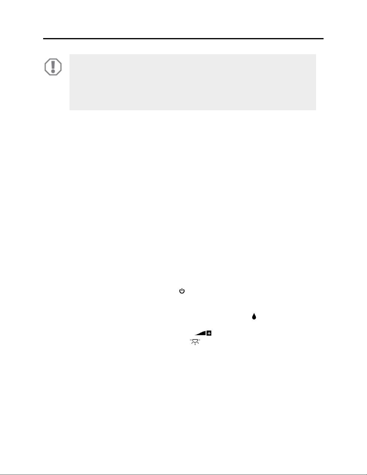
NOTICE!
•If kept in off mode for an extended period of time, there may be an odor
when turning it on again as a result of the absence of water cycling
through the straw filter. You may remedy this by running a few cycles
and the odor will naturally subside.
NOTICE!
•Never add anti-freeze, softener, perfume, fragrance or any other
substance than pure water in the reservoir. Adding substances could
create foam or potentially cause leaks.