Page 4
TABLE OF CONTENTS
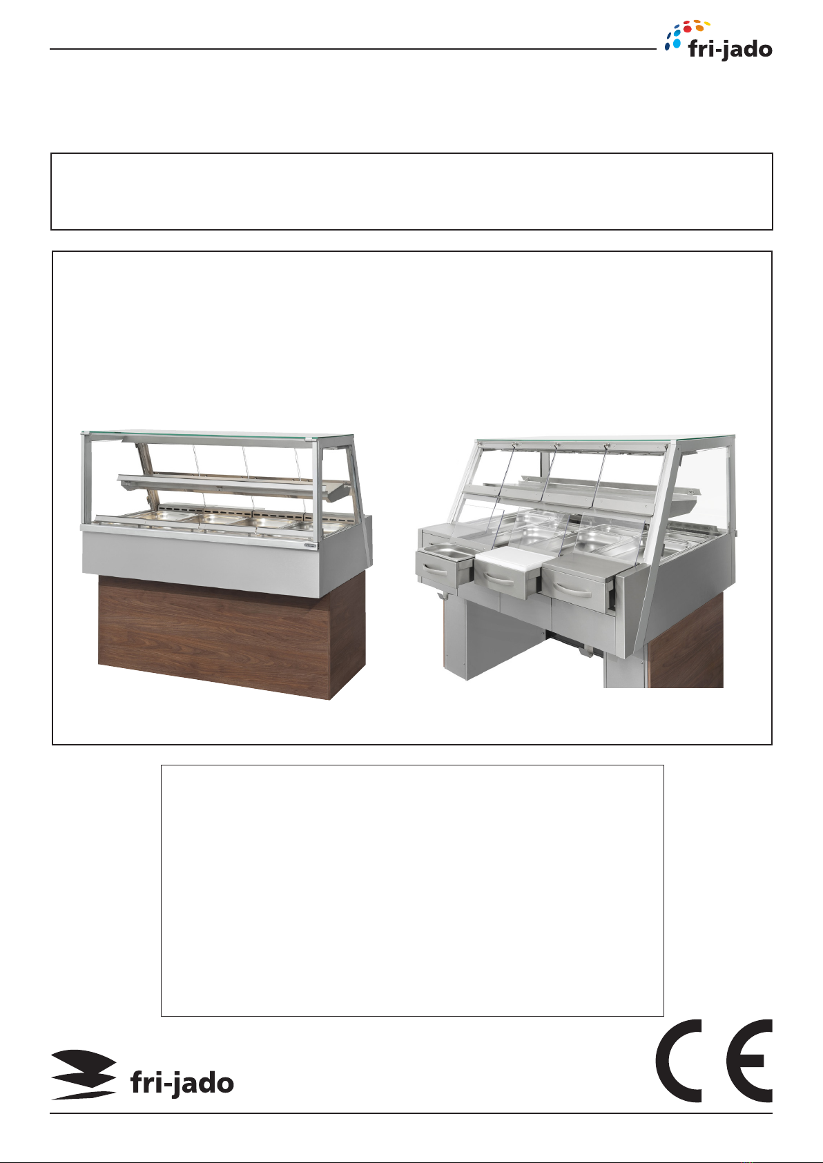
Service Manual Hot Deli Two Tier HDTT3/4/5/7 form 9124303 rev.06/2018
Index .......................................................................................................................................................... 4
General technical data.............................................................................................................................. 6
Technical data ....................................................................................................................................... 6
Programming instructions........................................................................................................................ 7
Display ................................................................................................................................................... 7
Removal and replacement of parts ........................................................................................................ 8
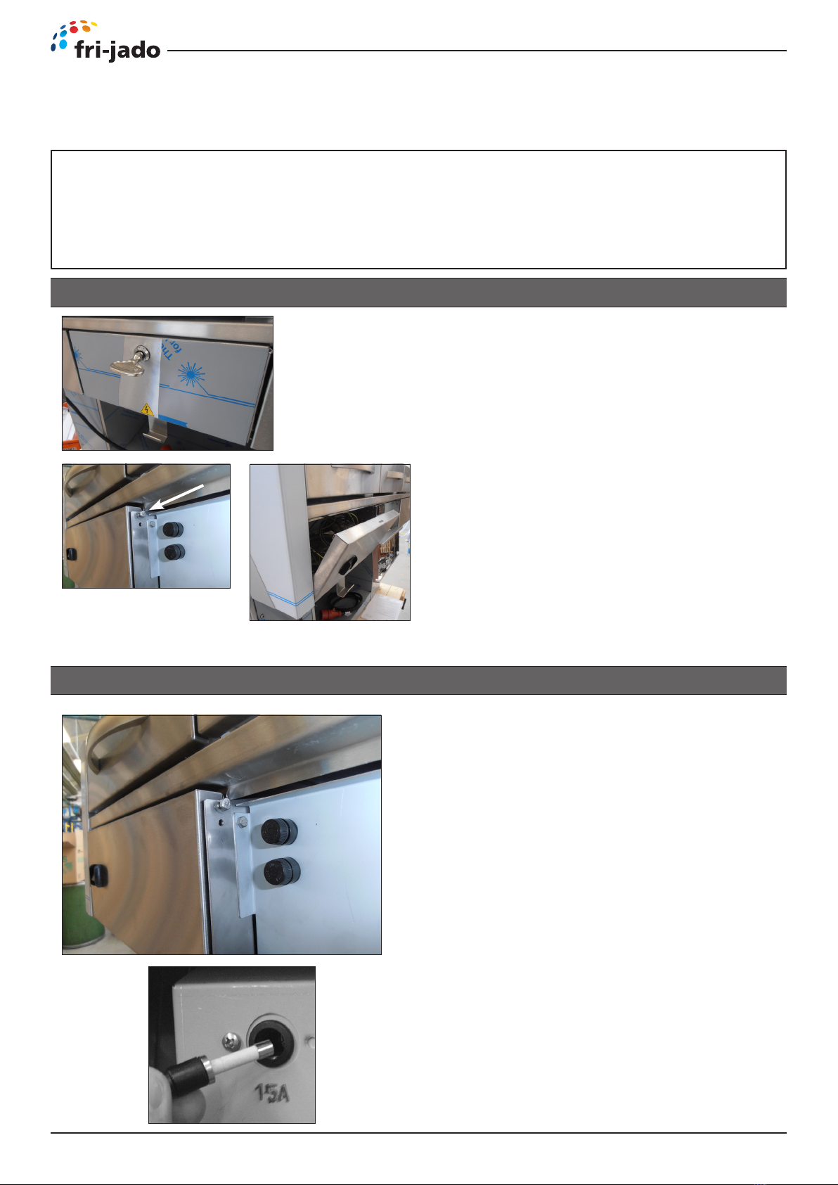
Panels back side ..................................................................................................................................... 8
Fuse and fuse holder ............................................................................................................................. 8
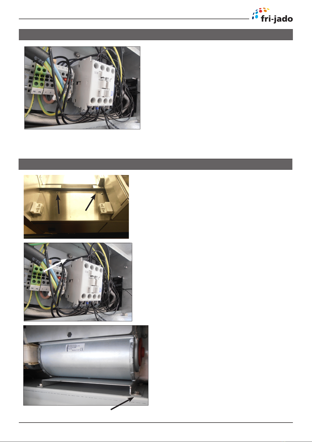
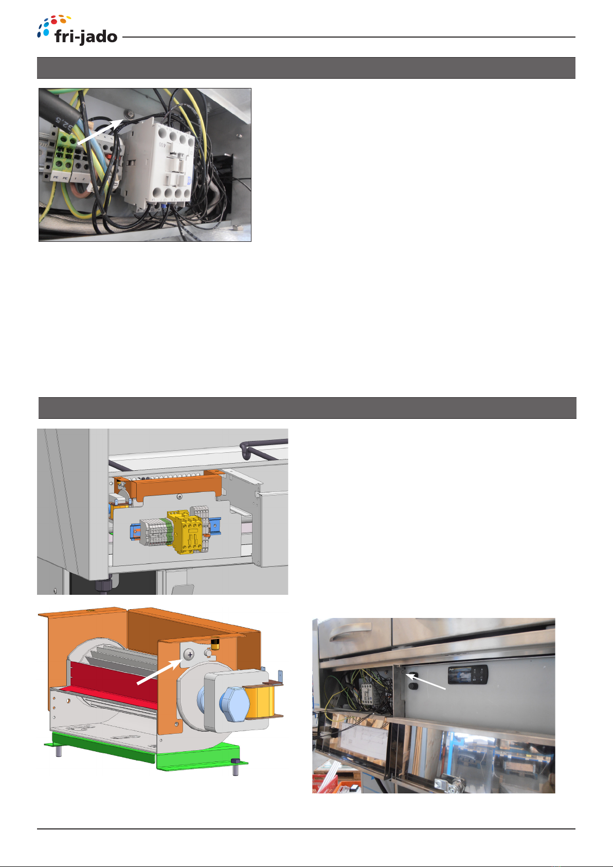
Contactor................................................................................................................................................ 9
Blower, left and right hand side ........................................................................................................... 9
Heating element, left and right hand side ........................................................................................ 10
Sensor Danfoss thermostat ................................................................................................................ 10
Thermostat Danfoss ERC 211 .............................................................................................................. 11
Ceramic element.................................................................................................................................. 11
Gas spring square model..................................................................................................................... 12
Front glass door square model ........................................................................................................... 13
Protection profile in front (bumper) .................................................................................................. 14
Electrical tests and service procedures.................................................................................................. 15
Heating element test........................................................................................................................... 15
Adjusting Danfoss ERC 211 thermostat.............................................................................................. 16
Danfoss ERC 211 Settings .................................................................................................................... 17
Control location Two Tier.................................................................................................................... 18
Troubleshooting ...................................................................................................................................... 19
Hot Deli Two Tier 3/4/5/7 .................................................................................................................... 19
Exploded views & partlists..................................................................................................................... 20
Hot Deli Two Tier 3-4-5-7 Square TC Assembly drawing ................................................................... 20
Hot Deli Two Tier 3-4-5-7 Square TC Components drawing 1........................................................... 24
Hot Deli Two Tier 3-4-5-7 Square TC Components drawing 2........................................................... 26
Hot Deli Two Tier 3-4-5-7 Square TC Underframe ............................................................................. 28
Electrical diagrams.................................................................................................................................. 30
Circuit diagram HDTT- 3 Square TC ................................................................................................... 30
Wiring diagram HDTT- 3 Square TC.................................................................................................... 31
Circuit diagram HDTT- 7 Square TC .................................................................................................... 32
Wiring diagram HDTT- 4-7 (4 of 7) Square TC.................................................................................... 33
Circuit diagram HDTT- 4 Square ......................................................................................................... 34
Wiring diagram HDTT- 4 Square ......................................................................................................... 35
INDEX