Fri-Jado Multi Deck 60 Essential User manual

Service Manual Multi Deck 60/100/120 / Classic Deck form 9123788 rev.07/2015
WWW.FRIJADO.COM
SERVICE MANUAL
MULTI DECK HOT MERCHANDISERS WITH IMPROVED AIR TECHNOLOGY
- NOTICE -
This manual is prepared for the use of trained Service Technici-
ans and should not be used by those not properly qualified. If
you have attended a trianing for this product, you may be quali-
fied to perform all the procedures in this manual.
This manual is not intended to be all encompassing. If you have
not attended training for this product, you should read, in its
entirety, the repair procedure you wish to perform to determine
if you have the necessary tools, instruments and skills required
to perform the procedure. Procedures for which you do not have
the necessary tools, instruments and skills should be performed
by a trained technician.
Reproduction or other use of this Manual, without the express
written consent of Fri-Jado, is prohibited.
MULTI DECK 60 ESSENTIAL - 4 LEVEL
MULTI DECK 100 ESSENTIAL - 4 LEVEL
MULTI DECK 60 TRANSPARENT LIGHT BOX
MULTI DECK 100 TRANSPARENT LIGHT BOX
MULTI DECK 120 TRANSPARENT LIGHT BOX
CLASSIC DECK HOT MERCHANDISER
Multi Deck 120 transparentMulti Deck 60 Essential Multi Deck 100 Essential Classis Deck Hot

Page 2 Service Manual Multi Deck 60/100/120 / Classic Deck form 9123788 rev. 07/2015

Service Manual Multi Deck 60/100/120 / Classic Deck form 9123788 rev. 07/2015 Page 3
Versions
Version Issue date
dd/mm/yy
Remarks
07/2015 01/07/2015 MD 60 and 100 Essential added. Glass front doors added. Update
exploded views. Various updates.

Page 4 Service Manual Multi Deck 60/100/120 / Classic Deck form 9123788 rev. 07/2015
INDEX
Index .......................................................................................................................................................... 4
General technical data.............................................................................................................................. 5
Removal and replacement of parts ........................................................................................................ 6
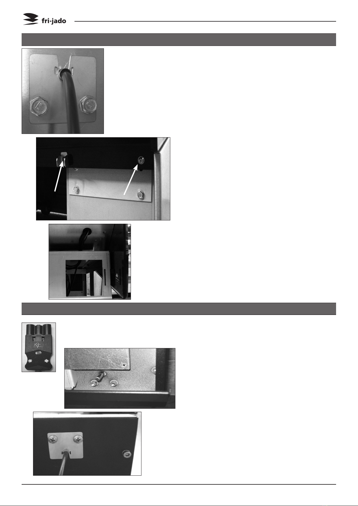
Panels bottom side (Multi Deck 60/100/120)........................................................................................ 6
Panels bottom side (Classic Deck) ......................................................................................................... 6
Back panel on bottom side (Classic Deck) ............................................................................................ 7
Cover plate on field wiring box ............................................................................................................ 7
Illumination/tumble switch ................................................................................................................... 7
Electronic ballast/Interference filter ..................................................................................................... 8
Roller blind............................................................................................................................................. 8
back panels............................................................................................................................................. 9
Thermostat (Danfoss) ............................................................................................................................ 9
Sensor Danfoss thermostat MD 60 and Classic Deck ......................................................................... 10
Sensor Danfoss thermostat MD 100 - 120 .......................................................................................... 10
Blower shelf heating ........................................................................................................................... 11
Heating element MD 60 and Classic Deck.......................................................................................... 12
Safety thermostat (reset)..................................................................................................................... 13
relay / contactor................................................................................................................................... 13
Replacing side glass ............................................................................................................................. 14
Mounting instruction glass door(s)..................................................................................................... 16
Electrical tests and service procedures.................................................................................................. 18
Heating element test........................................................................................................................... 18
PTC 1K Sensor test ............................................................................................................................... 18
Contactor and blower test .................................................................................................................. 18
Adjusting Danfoss EKC 102A thermostat ........................................................................................... 19
Adjusting Danfoss EKC 102A thermostat (continued)....................................................................... 20
Control locations.................................................................................................................................. 21
Troubleshooting ...................................................................................................................................... 22
Trouble shooting Multi Deck 60/100/120 and Classis Deck Hot ........................................................ 22
Exploded views & Part lists.................................................................................................................... 24
Multi Deck 60 Essential........................................................................................................................ 24
Multi Deck 100 Essential...................................................................................................................... 26
Multi Deck 60 Transparent light box .................................................................................................. 28
Multi Deck 100 / 120 Transparent light box ....................................................................................... 30
Classic deck .......................................................................................................................................... 34
Electrical diagrams.................................................................................................................................. 36
Circuit Diagram Multi Deck 60 Hot & Classic deck hot...................................................................... 36
Wiring Diagram Multi Deck 60 Hot & Classic deck hot ..................................................................... 37
Circuit Diagram Multi Deck 100 Hot................................................................................................... 38
Wiring Diagram Multi Deck 100 Hot ................................................................................................. 39
Circuit Diagram Multi Deck 120 Hot................................................................................................... 40
Wiring Diagram Multi Deck 120 Hot .................................................................................................. 41

Page 5Service Manual Multi Deck 60/100/120 / Classic Deck form 9123788 rev. 07/2015
GENERAL TECHNICAL DATA
This manual covers the Multi Deck 60, 100 and 120 Hot and the Classic Deck Hot series mer-
chandiser cabinets. The cabinets come in three sizes, 60, 100 and 120 centimeter.
• Multi Deck 60 Hot - Merchandiser 620 mm wide.
• Classic Deck Hot - Merchandiser 620 mm wide.
• Multi Deck 100 Hot – Merchandiser 1000 mm wide.
• Multi Deck 120 Hot – Merchandiser 1240 mm wide.
All of the information, illustrations and specifications contained in this manual are based on
the latest product information available at the time of printing.
Type MD 60
Hot
Classic Deck
Hot
MD 100
Hot
MD 120
Hot
Power (W) 3200 3200 3700 4400
Fuses needed with power con-
nection 230V, 1N ~ 50Hz ( 1 phase
with zero )
1x 16 A 1x 16 A 1x 20 A 1x 20 A
Fuses needed with power connec-
tion 400V, 3N ~ 50Hz ( 3 phases
with zero )
_ _ 3x 16 A 3x 16 A
Fuses needed with power con-
nection 400V, 3 ~ 50Hz ( 3 phases
without zero )
_ _ 3x 16 A 3x 16 A
Standard plug from factory single
pole
16 A 16 A _ _
Standard plug from factory 5-pole
According IEC309 and CEE-form
_ _ 16 A
3P+N+E
16 A
3P+N+E
Net weight (kg) 250 250 310 345
Gross weight (kg) 325 325 390 430
Height (mm) 1912 1912 1912 1912
Width (mm) 620 620 1000 1240
Depth (mm) 948 1035 948 948
Tools
• Standard set of tools.
• Metric wrenches, sockets and hex socket key wrenches.
• Multi-meter and AC current clamp meter.
• Insulation value tester (Megger)
• Temperature tester.
TECHNICAL DATA
GENERAL TECHNICAL DATA

Page 6 Service Manual Multi Deck 60/100/120 / Classic Deck form 9123788 rev. 07/2015
REMOVAL AND REPLACEMENT OF PARTS
WARNING: Disconnect the electrical power to the machine
at the main circuit box. Place a tag on the circuit box indica-
ting the circuit is being serviced.
1. Remove panel on the front side by lifting
it up with a screwdriver.
2. Slide the side panels backwards and re-
move these panels.
3. Loosen the screws from the back panel
and lift this panel out.
4. Reverse the procedure to install.
1. Slide stainless steel bottom panel towards
yourself and remove this.
2. Loosen the screws on the backside for the
side panels and remove both panels.
3. Remove the screws from the front panel
and remove the panel.
4. Reverse the procedure to install.
REMOVAL AND REPLACEMENT OF PARTS
PANELS BOTTOM SIDE (MULTI DECK 60/100/120)
PANELS BOTTOM SIDE (CLASSIC DECK)

Page 7Service Manual Multi Deck 60/100/120 / Classic Deck form 9123788 rev. 07/2015
REMOVAL AND REPLACEMENT OF PARTS
1. Remove the socket screws on the top side
and turn light fixture towards yourself.
2. Replace lamp.
3. Remove wiring from switch and remove
the switch by pushing the clamps on both
sides.
4. Reverse the procedure to install.
ILLUMINATION/TUMBLE SWITCH
1. Remove the panels on bottom side accor-
ding prior procedure.
2. Loosen the screws that secure the back
panel and remove this panel.
BACK PANEL ON BOTTOM SIDE (CLASSIC DECK)
1. Remove all panels on the bottom side
and the back panel on bottom side accor-
ding prior procedures.
2. Remove the screws that secure the box
and remove the cover plate.
3. Reverse procedure to install.
COVER PLATE ON FIELD WIRING BOX

Page 8 Service Manual Multi Deck 60/100/120 / Classic Deck form 9123788 rev. 07/2015
REMOVAL AND REPLACEMENT OF PARTS
1. Remove the screws on the top side and
remove cover panel.
2. Remove the nuts on the ballast and re-
move the wiring.
2a. Remove the screws on the filter and re-
move this filter.
3. Reverse the procedure to install.
ELECTRONIC BALLAST/INTERFERENCE FILTER
1. Remove the 2 socket screws and 3 screws
on the inside and remove the roller blind.
2. Place roller blind on a table and secure
this with a clamp.
3. Loosen the socket screws and slide the
blind upwards. Release the tension on the
blind by turning it anti clockwise until the
tension is low.
4. Place the new blind with the pin in the
holder. Put tension on the blind by tur-
ning this clockwise for 14 rotations (blind
with part nr. 9222038 needs 22 rotations).
5. Replace mounting plate and bearing on
the new blind.
6. Reverse the procedure to install.
ROLLER BLIND

Page 9Service Manual Multi Deck 60/100/120 / Classic Deck form 9123788 rev. 07/2015
REMOVAL AND REPLACEMENT OF PARTS
1. Remove the screws that secure the back
panel and remove this panel.
2. Remove the insulation.
3. Remove the screws that secure the cover
panel and remove this panel.
4. Reverse the procedure to install.
BACK PANELS
1. Remove the price rail assembly.
2. Remove the socket screws that secure the
fastening plate and remove the fastening
plate.
3. Loosen the blocking clips on the sides of
the thermostat and remove thermostat
from housing.
4. Remove the wiring from the thermostat.
5. Reverse the procedure to install.
Note: When changing the thermostat, first
always change parameter 07 to heating HE.
THERMOSTAT (DANFOSS)

Page 10 Service Manual Multi Deck 60/100/120 / Classic Deck form 9123788 rev. 07/2015
REMOVAL AND REPLACEMENT OF PARTS
1. Remove the thermostat according prior
procedure.
2. Remove the back panels + insulation +
cover panel.
3. Remove the panels on the bottom side.
4. Remove the bolts that secure the holder
and remove the holder with sensor.
5. Remove the screws on the front panel and
remove this panel.
6. Lead sensor through the grommet and
lead the sensor to the back side.
7. Reverse the procedure to install.
Note: See to it that the sensor is placed
straight inside the chamber.
SENSOR DANFOSS THERMOSTAT MD 60 AND CLASSIC DECK
1. Remove the thermostat according prior
procedure.
2. Remove the wiring of the sensor on the
thermostat.
3. Remove the bottom shelf. Don’t forget to
pul the plug out of the socket on the left
hand backside.
4. Remove the screws that secure the holder
and remove the holder with sensor.
5. 4. Reverse the procedure to instal.
SENSOR DANFOSS THERMOSTAT MD 100 - 120

Page 11Service Manual Multi Deck 60/100/120 / Classic Deck form 9123788 rev. 07/2015
REMOVAL AND REPLACEMENT OF PARTS
1. Remove the electric panel and all panels
on the bottom side according prior proce-
dures.
2. Remove the socket screws from the ben-
ded plate and fastening plate and remove
these plates.
3. Remove the wiring from the blower.
4. Remove the bolts on the round mounting
plate and remove the blower.
5. Remove the nut on the fan blade and
remove fan blade. (Left handed threads).
6. Remove the screws that hold the blower
and remove the blower from the round
mounting plate.
7. Reverse the procedure to install.
BLOWER SHELF HEATING
Turning direction anti-clockwise

Page 12 Service Manual Multi Deck 60/100/120 / Classic Deck form 9123788 rev. 07/2015
REMOVAL AND REPLACEMENT OF PARTS
1. Remove the back panels, insulation, cover
plate and the thermostat sensor according
prior procedures.
2. Remove all the panels on the bottom side
side + the back panel on bottom side ac-
cording prior procedures.
3. Remove the bended plate and fastening
plate on the back side according prior
procedures.
4. Remove the small cover plate on the back
side.
5. Remove the bolts that hold the cover tray
on the element and remove the tray.
6. Remove the wiring on the heating ele-
ment.
7. Remove the nut that secures the element
and remove the element from the inside.
8. Reverse the procedure to install.
HEATING ELEMENT MD 60 AND CLASSIC DECK

Md 60 and Classic
Deck (till serial
nr. 100047340)
Md 60-100-120 and
Classic Deck
Page 13Service Manual Multi Deck 60/100/120 / Classic Deck form 9123788 rev. 07/2015
REMOVAL AND REPLACEMENT OF PARTS
1. Remove the electric panel, back panels,
insulation and cover plate, and the cover
plate on the field wiring box according
prior procedures.
2. Remove the sensor from the clip.
3. Remove the wiring on the thermostat.
4. Remove the screws that secure the ther-
mostat and remove the thermostat.
5. Reverse procedure to install.
Note: Set the thermostat on 175°C.
SAFETY THERMOSTAT (RESET)
1. Remove all panels on the bottom side, the
back panel on bottom side and the cover
plate on the field wiring box according
prior procedures.
2. Remove the wiring from the relay.
3. Remove the screws that secure the relay
and remove the relay.
4. Reverse procedure to install.
RELAY / CONTACTOR
Reset button

Replacinga side glass in the MD
Remove all traces of glass and silicone past.
Remove the product stopper from the bottom
plate.
Take out the honeycomb profile and retainer.
Remove the bottom plate.
The attachment brackets are visible.
Remove the six screws from the top plate.
Remove the top plate.
Remove the insulation plates.The attachment brackets are visible.
Remove the old notches that were glued to the
glass by taking them from the attachment
brackets.
Use two spanners to proceed as follows:
Hold nut B with one spanner.
Detach nut A with the other spanner.
Remove the brackets and the old notches.
Page 14 Service Manual Multi Deck 60/100/120 / Classic Deck form 9123788 rev. 07/2015
REMOVAL AND REPLACEMENT OF PARTS
REPLACING SIDE GLASS

Putting the new glass in place
Attach all nuts B by hand.
Hold nut B in position using a spanner.
Tighten nut A firmly using a spanner.
Put the insulation plates in the top !
Apply the top plate.
Thoroughly clean the side and remove any
traces of fat.
Glue a piece of foam of 1/8". (X) on the top
side.
Apply silicone paste following the pattern as
shown in above picture.
Position the notches which are glued to the
glass in the holes.
Put the brackets on the threaded studs.
Put the screws in the top plate
Put the bottom plate in the unit.
Position the honey comb profile with the
retainer in the opening.
Place the product stopper in the channel in
the bottom plate.
X
Page 15Service Manual Multi Deck 60/100/120 / Classic Deck form 9123788 rev. 07/2015
REMOVAL AND REPLACEMENT OF PARTS

Page 16 Service Manual Multi Deck 60/100/120 / Classic Deck form 9123788 rev. 07/2015
REMOVAL AND REPLACEMENT OF PARTS
MOUNTING INSTRUCTION GLASS DOOR(S)
Note: The models MD 100 ans 120 have double glass doors. See also next page.

Page 17Service Manual Multi Deck 60/100/120 / Classic Deck form 9123788 rev. 07/2015
REMOVAL AND REPLACEMENT OF PARTS
Part nr. Description
9220084S Front door ass. MD 60
9220085S Front door ass. MD 100
9220086S Front door ass. MD 120
9220078S Door ass. MD 60
9220077S L or R door ass. MD 100
9220076S L or R door ass. MD 120
Front door ass.
Front door ass.
Door ass.

ELECTRICAL TESTS AND SERVICE PROCEDURES
Page 18 Service Manual Multi Deck 60/100/120 / Classic Deck form 9123788 rev. 07/2015
WARNING: Disconnect the electrical power to the machine
at the main circuit box. Place a tag on the circuit box indica-
ting the circuit is being serviced.
ELECTRICAL TESTS AND SERVICE PROCEDURES
HEATING ELEMENT TEST
Type Wattage/Vol-
tage
Resistance Ω -5% +
10%
Current A
MD 60 +Classic Deck 1500 / 230 35.3 6.5
MD 100 900 / 230 58.8 3.9
MD 120 1060 / 230 50.0 4.6
Note: When testing the resistance of the element remove the wiring.
Temperature Resistance
°F °C ± 10 Ohms
60 16 930
70 21 970
80 27 1016
90 32 1056
100 38 1107
125 52 1227
150 65 1347
200 94 1636
250 121 1935
1. Remove the right side panel according
prior procedure.
2. Remove the wiring from the sensor.
3. Connect a temperature sensor to the probe
for comparison.
4. Test the probe with an Ohmmeter.
PTC 1K SENSOR TEST
CONTACTOR AND BLOWER TEST
Type Description Voltage Resistance
MD 60-100-120 Contactor ABB 230 V Resistance of coil (A1 - A2) ~ 525 Ω
MD 60-100-120 Blower 230 V ~55 Ω
Note: When testing the resistance remove the wiring.

Page 19
ELECTRICAL TESTS AND SERVICE PROCEDURES
Service Manual Multi Deck 60/100/120 / Classic Deck form 9123788 rev. 07/2015
ADJUSTING DANFOSS EKC 102A THERMOSTAT
Note: In order to adjust the thermostat, first remove the thermostat according prior proce-
dure.
Changing set point
1. Press the middle button until the temperature value is shown.
2. Change value with upper or lower button.
3. Press the middle button to confirm.
Setting internal parameters
1. Press the upper button for 3 seconds. In display the first parameter appears (ro1).
2. Press the middle button to read out value.
3. Change value with upper or lower button.
4. Press the middle button to confirm.
5. Press the lower button for the next parameter. Follow instructions 2 to 4.
When no button is pressed after last confirmation, system goes back to normal operation
mode after 20 seconds.
Replacing of thermostat
When you install a new thermostat, then always change parameter r05 first to 0 (°C) and
change parameter o07 to HE. Otherwise some other parameters cannot be changed to the
desired value. Otherwise some other parameters cannot be changed to the desired value.
You can run through the parameters with the up or down keys, once you are inside the para-
meter settings.
Options
1. Return to factory settings. Turn the power off. Press and hold the upper and lower button
and switch the power on at the same time.
2. Actual temperature of sensor 1 (Thermostat). Press up key shortly 2 times.
Error codes on display
E1: Fault in controller.
E29: Cabinet sensor broken or wiring problem sensor.

ELECTRICAL TESTS AND SERVICE PROCEDURES
Page 20 Service Manual Multi Deck 60/100/120 / Classic Deck form 9123788 rev. 07/2015
MD 60-100-120
CLD 60
Setpoint °C 85
r01 Differential °C 1
r02 Higher setpoint limit °C 99
r03 Lower setpoint limit °C 0
r04 Off-set temperature indication °C -5
r05 Temperature unit (°C / °F) °C °C
r09 Correction of signal from air output °C 0
r12 Start / stop of temperature control 1
c01 Minimum “ON” time compressor min 0
c02 Minimum “OFF” time compressor min 0
c30 Reversed function of relay contact OFF
d01 Defrost method (EL / OFF) OFF
d02 Defrost end temperature °C 6
d03 Defrost interval hour 8
d04 Maximum defrost time min 45
d05 “ON” delay after defrost min 0
d10 Defrost sensor (0=time, 1=air) 0
d13 Defrost at start up no
o01 Output delay after start up sec 0
o05 Access code all settings 0
o06 Sensor type ptc
o07 Warm (HE) / cold (rE) HE
o15 Step value display (yes = 0.5°C / no = 1°C) no
o67 Store current parameter as factory default OFF
u58 Status relay 1 -
Parameters Danfoss EKC 102A thermostat
ADJUSTING DANFOSS EKC 102A THERMOSTAT (CONTINUED)
Other manuals for Multi Deck 60 Essential
1
This manual suits for next models
7
Table of contents
Other Fri-Jado Merchandiser manuals