Frimax MAXON Ocultas TE-20 Series Instruction Manual

Serie Ocultas
TE-20 TE-25 TE-30
www.frimax.mx
MANUAL DE USUARIO

ÍNDICE
TABLE OF CONTENTS
SUMMARY OF CHANGES: M-16-34 REV C ............................. 4
WARNINGS................................................................................ 5
RECOMMENDED DAILY OPERATION CHECKS..................... 7
DECALS ................................................................................... 10
FORKLIFT ADVISORY ............................................................ 13
ROADSIDE OPERATION ADVISORY...................................... 14
OPERATION ............................................................................ 15
USING CART STOPS (IF EQUIPPED) .................................... 21

ÍNDICE
PAGE DESCRIPTION OF CHANGE
Cover Updated revison, date & copyright statement.
Deleted references to TE-15 throughout manual.
SUMMARY OF CHANGES: M-16-34 REV C

1
ADVERTENCIA
1. Incorrect operation of this Liftgate can result in serious personal
injury. Comply with WARNINGS and Liftgate operating instructions
in this manual. Do not allow untrained persons or children to operate
the Liftgate. If you need to replace an Operation Manual, additional
copies are available from:
MAXON Lift Corp.
11921 Slauson Ave
Santa Fe Springs, CA 90670
(800) 227-4116
NOTE: For latest version manuals (and replacements), down-
load manuals from Maxon’s website at www.maxonlift.com.
2. Do not exceed rated load capacity of the Liftgate which is 2000 LB for
model TE-20, 2500 LB for model TE-25 and 3000 LB for model TE-
30.
3. Do not allow any part of your body to be placed under, within, or
around any portion of the moving Liftgate or its mechanisms, or in
a position that would trap them between the platform and the floor
of truck body (or between platform and the ground) when Liftgate is
operated.
4. Consider the safety and location of bystanders and location of
nearby objects when operating the Liftgate. Stand to one side of
platform while operating the Liftgate. Be certain that the area the
Liftgate will move through during operation is clear of all obstacles.
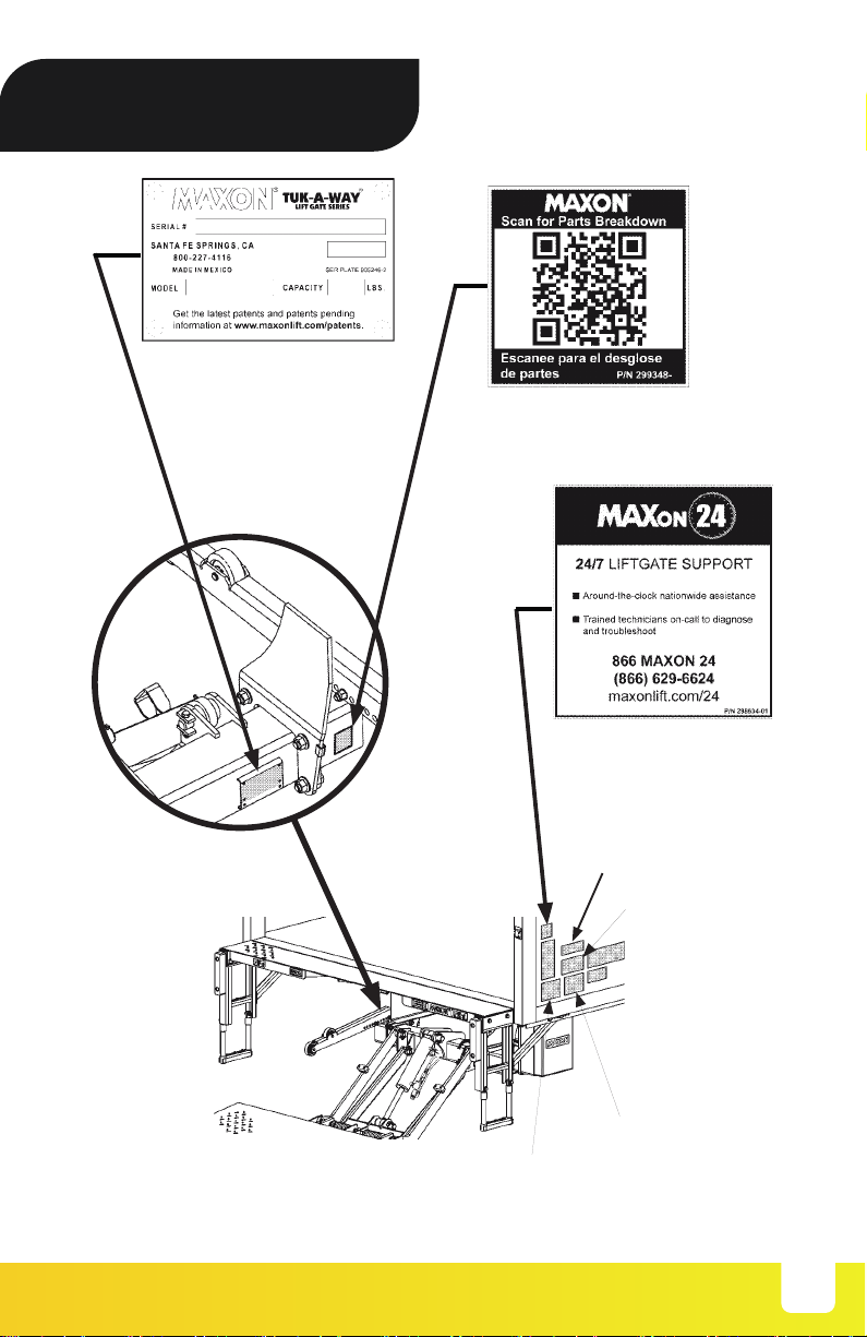
5. Comply with all attached instruction decals and warning decals.
11. Above all, USE GOOD COMMON SENSE when operating this
Liftgate.
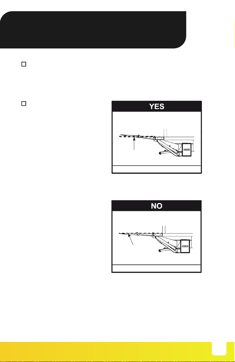
8. Do not move vehicle unless Liftgate is correctly stowed.
6. Keep decals clean and legible. If decals are illegible or missing,
have them replaced. Get free replacement decals from Maxon.
7. Never drive a forklift on the Liftgate platform.
10. A correctly installed Liftgate will operate smoothly and reasonably
quiet. The only noticeable noise, during Liftgate operation, is from
the power unit while the platform is raised. Listen for scraping,
grating and binding noises and have the problem corrected
before continuing to operate the Liftgate.
9. Correctly stow platform when not in use. Extended platforms
could create a hazard for people and vehicles passing by.
12. Never use a cell phone while operating the Liftgate.

2
LIFTGATE TERMINOLOGY
EXTENSION
PLATE
LIFT FRAME
CONTROL
SWITCH
PARALLEL
ARM
PLATFORM
LIFT
CYLINDER
PUMP
BOX
MAIN
FRAME
WEDGE FLIPOVER
PLATFORM
OPENER
DOCK
BUMPER
FLEX STEP
TORSION
SPRING
TE-25 OR TE-30 SHOWN
FIG. 6-1

3
RECOMMENDED DAILY
OPERATION CHECKS
Make sure vehicle battery is fully charged and battery terminal connec-
tions are clean and tight.
Visually check that pump cover is bolted on securely and undamaged.
Look for hydraulic fluid leaking from the pump box.
Before operating the Liftgate, the operator should do the following:
Visually check that control switch is in place and undamaged.
Use the operation instructions in this manual to lower the Liftgate to
the ground and open the platform and flipover.
Check main frame, lift arms, parallel arms and platform openers for
cracks and bends. Make sure rollers, on the platform openers, roll freely.
Also, make sure all bolts and pins are in place and undamaged.
Visually check for cracks and bends on the extension plate. Also, make
sure fasteners are in place and undamaged and extension plate is
clean (no oil, debris, or corrosion).
Make sure main frame, lift arms, parallel arms and platform openers are
clean (no oil, debris, or corrosion).
Visually check that all decals are in place (see DECALS page). Also,
make sure decals are legible, clean, and undamaged.
NOTE: Before you check the Liftgate, park vehicle on flat
ground and set the parking brake.
NOTE: If any of the following operation checks reveal a
need to service or repair Liftgate, do not operate
the Liftgate until a qualified mechanic services or
repairs the Liftgate.

4
RECOMMENDED DAILY
OPERATION CHECKS
With the platform at vehicle bed
height and no load on platform,
outboard edge of platform must
be higher than extension plate
as shown in the YES illustration
(FIG. 8-1). If the platform is tilted
up like the YES illustration, you
can operate Liftgate. If platform
is level at bed height like the
NO illustration (FIG. 8-2), do
not operate the Liftgate. (See
NOTEat beginning of the DAILY
OPERATION CHECKS.) PLATFORM AT BED HEIGHT
FIG. 8-1
NO
PLATFORM AT BED HEIGHT
FIG. 8-2
YES
LEVEL
LINE
LEVEL
LINE
Check the hydraulic cylinders for leaking seals and hose connections.
Follow the hydraulic hoses (or return lines for gravity down Liftgates)
from the cylinders to pump box. Make sure all hoses are connected at
both ends and there are no cracks, chafing, and fluid leaks.

5
Check the platform and flipover for cracks, holes, and bends on the
load-carrying surface and side plates. Also, make sure torsion bars, coil
springs, and fasteners are in place and undamaged.
Make sure platform and flipover load-carrying surfaces are clean (no
oil, debris, or corrosion).
Use the operation instructions in this manual to operate the Liftgate
through one cycle without a load on the platform. RAISE the platform
to vehicle bed height. Next, lower the platform to ground level.
When the Liftgate is moving, listen for unusual noises and look for jerk-
ing motion or uneven movement on either side of the platform.
If service or repairs are not required (or if completed), stow the Liftgate.
With the platform unfolded and
on the ground, check if the shack-
les and the tip of platform touch
the ground at the same time as
shown in the YES illustration
(FIG. 9-1). If the platform looks
like the YES illustration, you
can operate Liftgate. If the tip
of the platform is off the ground
and platform looks like the NO
illustration (FIG. 9-2), or if the
shackles are off the ground, do
not operate the Liftgate. (See
NOTE at beginning of the DAILY
OPERATION CHECKS.)
PLATFORM UNFOLDED
ON THE GROUND
FIG. 9-1
TIP OF
FLIPOVER LEVEL
GROUND
YES
SHACKLE
NO
LEVEL
GROUND
TIP OF
FLIPOVER
SHACKLE
PLATFORM TIP OFF
THE GROUND
FIG. 9-2
RECOMMENDED DAILY
OPERATION CHECKS

DECALS
6
NOTE: Preferred decal layout is shown, Decals on the Liftgate are
attached at the factory. If vehicle does not permit this layout,
decals in the manual and decal kit must be applied so that they
are easily visible when approaching vehicle to operate Liftgate.
Use good common sense when locating these decals on
vehicle.
NOTE: Ensure there is no residue, dirt or corrosion where decals
are attached. If necessary, clean surface before attaching
decals.
CAPACITY DECAL
(SEE TABLE 12-2)
STOW WARNING DECAL
P/N 282847-02
WARNING DECAL
P/N 265736-03
INSTRUCTION DECAL
P/N 285800-03
UP DECAL
P/N 299038-01
DOWN DECAL
P/N 299038-01

7
PARTS QR CODE DECAL
P/N 299348-01 (TE-20)
P/N 299348-02 (TE-25,TE-30)
MAXON 24/7
SUPPORT DECAL
P/N 298634-01
SERIAL PLATE (REF)
DECAL “A”
DECAL “F”
DECAL “C”
DECAL “B”
FIG. 11-1
DECALS

8
CAPACITY DECALS
TABLE 12-1
MODEL DECAL P/N CAPACITY
TE-20 220387 2000 POUNDS (907 KG)
TE-25 220382 2500 POUNDS [1134 KG]
TE-30 220388 3000 POUNDS [1360 KG]
DECAL SHEET
P/N 282522-01
FIG. 12-1
DECALS

FORKLIFT ADVISORY
9
WARNING
!
Keep Forklift OFF of Platform.
FIG. 13-1

10
ROADSIDE OPERATION
ADVISORY
Operating the Liftgate by the side of a busy road with vehicle traffic
increases the chance of personal injury and damage to Liftgate,
cargo & vehicle. Making the loading area more visible to passing
traffic can help reduce the chance of injury and damage.
WARNING
!
NOTE: MAXON recommends placing at least 2 traffic cones on the
traffic side of the platform loading area as illustrated below.
Remove cones after platform is stowed and before moving the
vehicle.
VEHICLE TRAFFIC
APPROACHING
FROM THIS SIDE
TRAFFIC CONES POSITIONED BY PLATFORM LOADING AREA
FIG. 14-1

OPERATION
11
Never operate control switch while unfolding (and folding)
platform and flipover. Always use handle on side of flipover to
unfold (and fold) flipover. Holding the flipover any other way can
create a hazard and injure operator.
WARNING
!
1. Push the toggle switch
to DOWN position
(FIG. 15-1A) until
shackles touch the
ground.
LOWERING PLATFORM
FIG. 15-1
FIG. 15-1A
SHACKLE
2. Use handle on bottom of
platform (FIG. 15-2A) to
unfold the platform and
flipover (FIG. 15-2).
FIG. 15-2A
UNFOLDING PLATFORM & FLIPOVER
FIG. 15-2
DOWN

OPERATION
12
3. Unhook (if equipped) and unfold the flipover as
follows. If equipped with hook, press down on the
flipover and rotate hook away from the handle (FIGS.
16-1 and 16-1A). Then, use handle (FIG. 16-1B) to
unfold the flipover.
UNFOLDING FLIPOVER
FIG.16-1
FIG. 16-1B
FIG. 16-1A
RAISING & LOWERING PLATFORM
FIG. 16-2
4. Raise the platform (FIG. 16-2) by pushing the toggle switch
to the UP position (FIG. 16-2A). If loading (or unloading) the
platform, wait a second before releasing the toggle switch,
after platform reaches bed height. To lower the platform,
push the toggle switch to the DOWN position (FIG. 16-2B).
PLATFORM
NOTE: While operating the Liftgate, release toggle switch to stop the
platform.
FIG. 16-2B
FIG. 16-2A
UP
DOWN

OPERATION
13
5. Load the platform at ground
level as shown in FIG. 17-1.
LOADING PLATFORM AT GROUND LEVEL
FIG. 17-1
6. Raise the platform to bed
height (FIG. 17-2). Move the
load off platform into vehicle
(FIG. 17-2).
UNLOADING PLATFORM AT BED HEIGHT
FIG. 17-2
INBOARD
EDGE
PLATFORM
VEHICLE
BODY
PLATFORM
WARNING
!
A load should never extend past the edges of the platform. Do not
place unstable loads on platform and do not allow load to exceed
the lifting capacity of the Liftgate. If standing on platform, do not
allow your feet to extend beyond the inboard edge of the platform.

LOADING PLATFORM AT BED HEIGHT
FIG. 18-1
PLATFORM
7. Load the platform at bed
height (FIG. 18-1) as fol-
lows. Push load out of the
vehicle to correct position
on the platform. Place all
loads as close as possible
to the inboard edge of
the platform with heaviest
part toward the truck body
as shown in FIG. 18-1.
If standing on platform
with the load, stand in the
footprint area shown and
comply with the WARNING
on previous page.
Pulling the load from vehicle to platform can result in a fall from
platform and serious injury. When unloading vehicle, always
push the load out on the platform.
WARNING
!
VEHICLE
BODY
8. Lower the platform to
ground level (FIG. 18-2).
Move load off the platform
(FIG. 18-2).
UNLOADING PLATFORM AT GROUND LEVEL
FIG. 18-2
PLATFORM
INBOARD
EDGE
14
OPERATION

OPERATION
15
NOTE: Platform raised off the ground makes it easier to grasp and
fold the flipover.
10. Fold flipover on the platform
using handle on the flipover
(FIG. 19-2A). If equipped,
hook the platform to handle
on flipover (FIG. 19-2B).
FOLDING FLIPOVER ON PLATFORM
FIG. 19-2
FIG. 19-2A
9. Before moving the vehicle,
prepare the Liftgate as fol-
lows. Make sure load is
removed from platform. If
the platform is at bed height,
push the toggle switch to the
DOWN position as shown in
FIG. 19-1A. Release toggle
switch when platform 2” off the
ground (FIG. 19-1).PLATFORM 2” OFF THE GROUND
FIG. 19-1
Never move the vehicle unless the Liftgate is properly stowed.
WARNING
!
FIG. 19-2B
DOWN
FIG. 19-1A

OPERATION
16
12. Stow the platform (FIG. 20-2) by push-
ing the toggle switch to the UP posi-
tion (FIG. 20-2A). Wait a second, after
platform is stowed all the way, before
releasing toggle switch.
13. Liftgate is ready for transport.
CORRECTLY STOWED PLATFORM
FIG. 20-2
11. Use handle on bottom of plat-
form (FIG. 20-1A) to lift and
fold the platform and flipover
(FIG. 20-1).
FOLDING PLATFORM & FLIPOVER
FIG. 20-1
FIG. 20-1A
FIG. 20-2A
UP

17
USING CART STOPS
(IF EQQUIPPED)
CAUTION
!
NOTE: Some Liftgates are equipped with single or dual cart stops.
Cart stops prevent loaded carts from rolling off outboard end
of platform. Single cart stops are 1 section, about the same
as overall width of platform, and operate with one set of
controls. Dual cart stops are 2 identical sections, with a com-
bined width about the same as overall width of platform, and
each is independently operated with separate controls (1 set
of controls per cart stop). The following procedure shows dual
cart stops. A single cart stop operates the same way.
1. At ground level, move load
on platform with cart stops as
shown in FIG. 21-1.
To prevent injuries caused by tripping and falling, make sure
cart stops are closed before walking on and off outboard end of
platform.
LOADING PLATFORM AT GROUND LEVEL
(CART STOPS CLOSED)
FIG. 21-1
NOTE: Cart stops are usually closed when not in use. If you find the
carts stops are already open when rolling a load from the
ground to the platform, you may roll the load over the cart
stop. The cart stop will close temporarily as the load crosses
and reopen when the load is off the cart stop.
CART STOPS
This manual suits for next models
2
Table of contents
Other Frimax Industrial Equipment manuals
Popular Industrial Equipment manuals by other brands

Heinzmann
Heinzmann StG 40.90-09 PD instruction manual

ADCA
ADCA FLT Installation and maintenance instructions

Kval
Kval 990-H Operation manual

schmersal
schmersal AZM201Z-I2-ST-T-1P2PW-2965-2 Operation and assembly instructions

HEIDENHAIN
HEIDENHAIN MSE 1110 installation instructions

ABB
ABB HT563365 Operation manual