1 STANDARDS AND GENERAL WARNINGS
M-7.3-16 Rev. 05 09/03/15 BLOOD BANK REFRIGERATORS AND PLASMA FREEZER 7
Use and maintenance manual
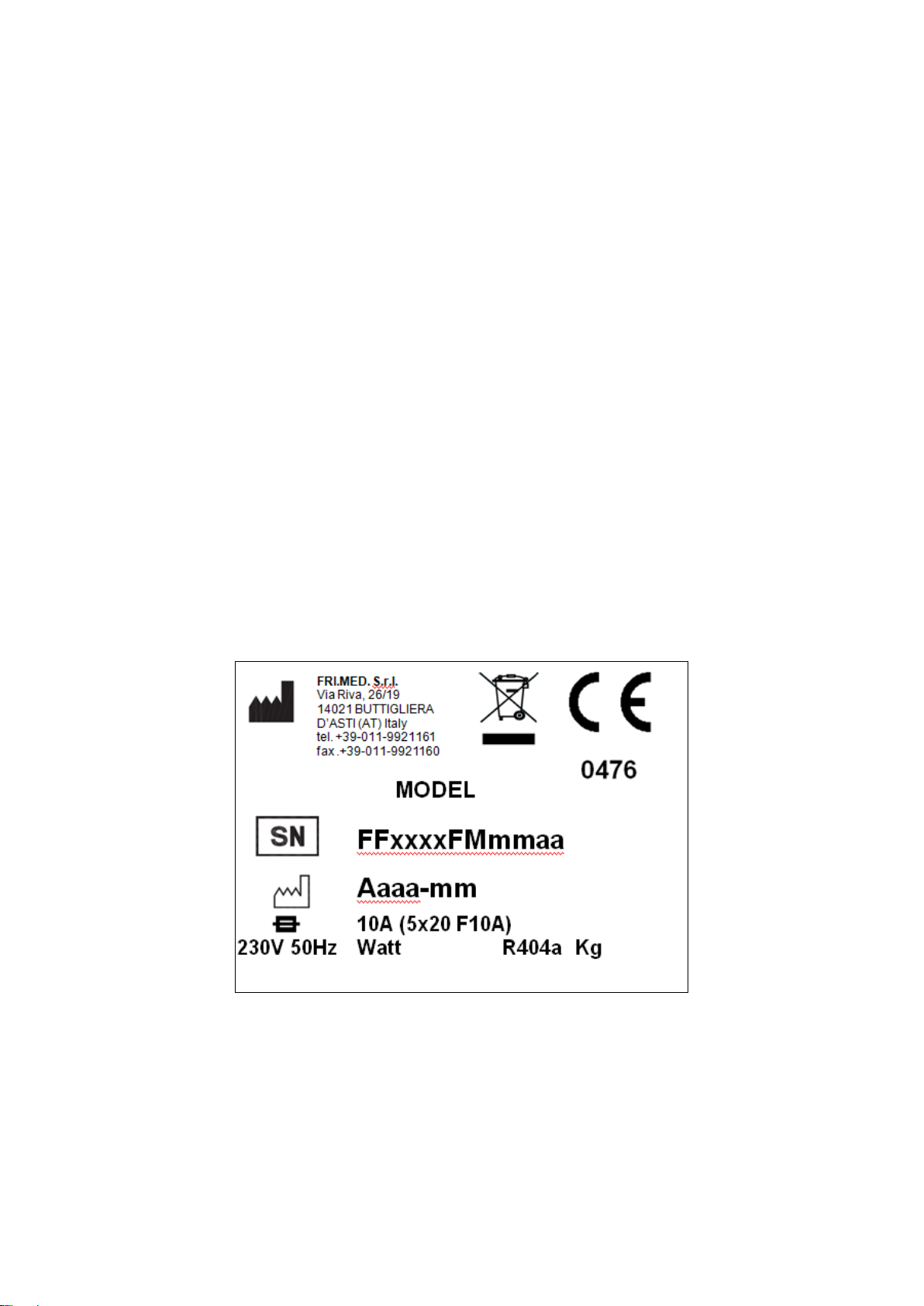
1.1 CERTIFICATION
All Blood Bank refrigerators are produced in accordance with European Community Regulations
applicable at the time of its appearance on the market and are certified as Medical Device in
accordance with European Directive 93/42/EEC and following amendments and integrations.
1.2 TESTING AND WARRANTY
The appliance is tested in our works in compliance with established regulations and then shipped
ready for use.
The warranty grants the right for the replacement of those parts which turn out to be defective,
except for electric and electronic components. Every apparent vice and any difference from the
order must be communicated, under pain of decay, to the selling firm within 5 days from the
receipt of the goods. Any other vice (non-apparent) must be communicated within 5 days from its
finding, and anyhow within the maximum warranty term. The Buyer has the only right to claim for
defective parts replacement: every right of compensation for any direct or indirect damage is
excluded. The damage due to uncorrected installation of the equipment or the lack of ordinary
maintenance/cleaning of the condenser are reasons of immediate expiry of the warranty. The
warranty is valid only for the original purchaser and it will never bring the replacing of the
equipment. The replacement of defective parts will be made at FRI.MED S.r.l. factory, where the
returned goods must be delivered free of any transport expense; the company will arrange to
deliver them back ex-works.
1.2 AIM, CONTENTS AND INTENDED USER OF THIS MANUAL
This manual has been prepared with the objective to supply all instructions required for the correct
use of the appliance and to keep it in optimal condition. It also contains important user safety
information.
The following professional roles are explained in order to define the responsibilities of each
involved parties:
Installer: a qualified technician who installs the appliance in accordance with the instructions
herein contained.
User: the person who, after having read this manual carefully, uses the appliance in accordance
with the intended specification of use described in this manual.
User’s responsibilities:
ensure that the product is kept at suitable temperatures without exceeding +38° of ambient
temperature;
be aware of the regulations governing the conservation of products to refrigerate and to
observe any whatsoever hygiene indications that may be applicable.
The user is obliged to read carefully the manual and refer to its information at all times. Particular
attention must be paid to the contents of heading 1.4 General safety warnings.
Routine maintenance technician: qualified operator able to perform routine maintenance of the
appliance by following the instructions in this manual (can be the customer too).
Service engineer: qualified technician, authorised by the manufacturer to perform extraordinary
maintenance of the appliance.
The symbol appears at certain points in the manual to draw the reader’s attention to important
safety information.
The manufacturer declines any whatsoever responsibility in case of improper use of the appliance
deviating from the reasonably construed intended use, and for all operations carried out that are
not in compliance with the instructions reported in the manual.
This manual must be stored in an accessible and known place for all operators (installer, user,
routine maintenance technician, service engineer).