4titude TubeMarker 2 User manual

4titude Ltd. • The North Barn • Surrey Hills Business Park Damphurst Lane • Wotton • Surrey • RH5 6QT
TubeMarker™ 2
Operation Manual
Version: 2.0
TubeMarker™ 2, Operation Manual V2.0 • en1 • 09.2018

TubeMarker™ 2
TubeMarker™ 2, Operation Manual V2.0
4titude Ltd.
The North Barn, Surrey Hills Business Park
Damphurst Lane, Wotton, Surrey, RH5 6QT
UK
Disclaimer
Copyright Notice
No part of this manual may be reproduced or transmitted in any form or by any means, electronic or mechanical,
for any purpose, without prior written permission of 4titude Ltd.
Safety Information
This operation manual contains important operating and maintenance instructions which must be read, understood,
and followed by the product user. Failure to use this product according to this operation manual may degrade
or defeat the protection normally provided by this product. Read this manual prior to product use and keep it for
future reference.
Safety Instructions
1. Keep the device away from humidity.
2. Before you connect the equipment to the power outlet, please check the voltage of the power source.
3. Take care not to spill any liquid on the printer.
4. Forsafetyandwarrantyreasons,onlyqualiedservicepersonnelshouldunscrewthebaseoftheinstrument
or touch the back of the LCD display.
5. Turn off the power and unplug the device before maintenance.
6. Do not touch moving parts.
7. Only use the TubeMarker™ 2 with the AC/DC adapter provided with the equipment.
8. If the power supply is damaged please do not attempt to use the TubeMarker™ 2.
9. DonotpositiontheTubeMarker™2sothatitisdifculttooperatethedisconnectingdevice(detachableplug).
Iftheequipmentisusedinamannernotspeciedbythemanufacturer,theprotectionprovidedbytheequipment
may be impaired.
This product has been tested to meet the requirements of IEC/EN 61010-1:2010, UL 61010-1 (2012) and CAN/
CSA-C22.2 No. 61010 (2012).

5
TubeMarker™ 2
TubeMarker™ 2, Operation Manual V2.0
Table of Contents
1 TubeMarker™ 2 Introduction ..........................................................................................................6
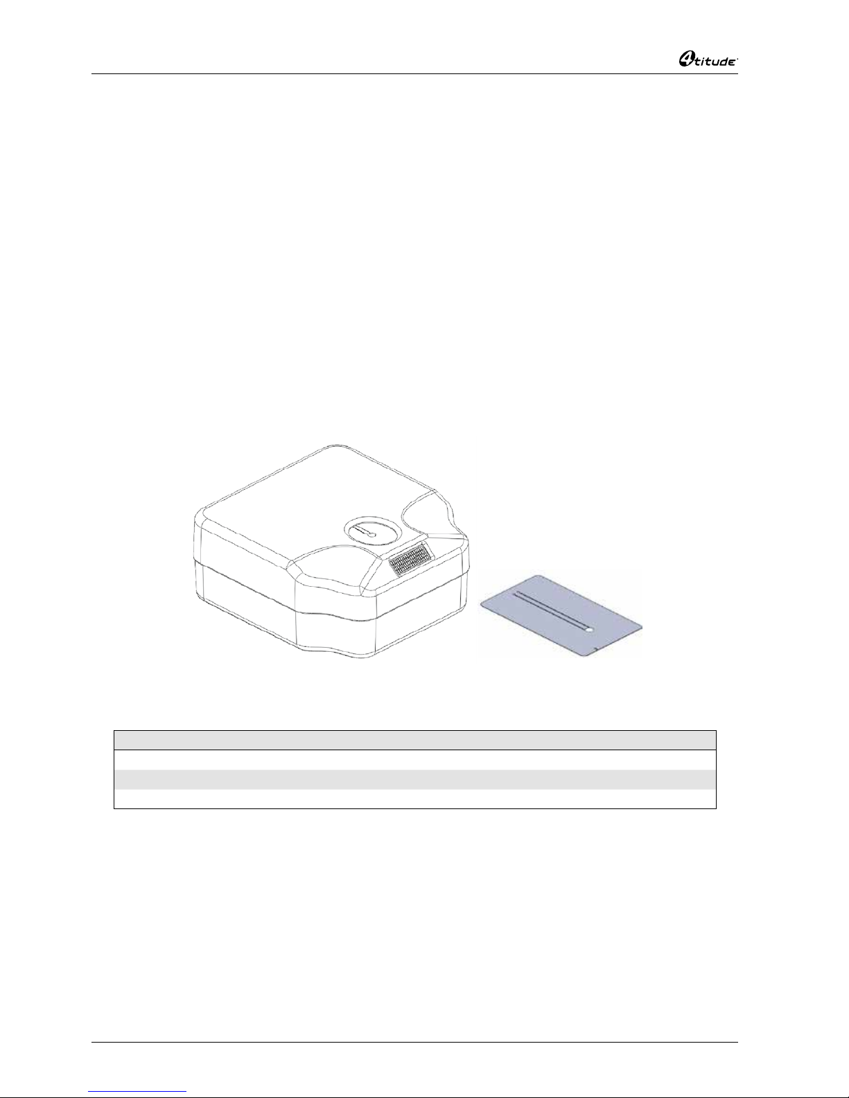
1.1 The Instrument…………………………………………………………………………………………………………6
1.2 Package Contents ……………………………………………………………………………………………………6
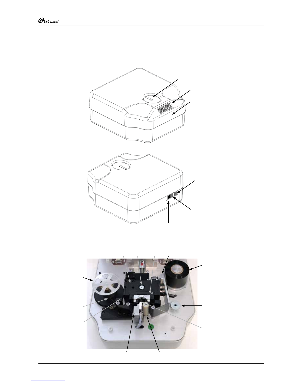
1.3 TubeMarker™ 2 Parts ………………………………………………………………………………………………7
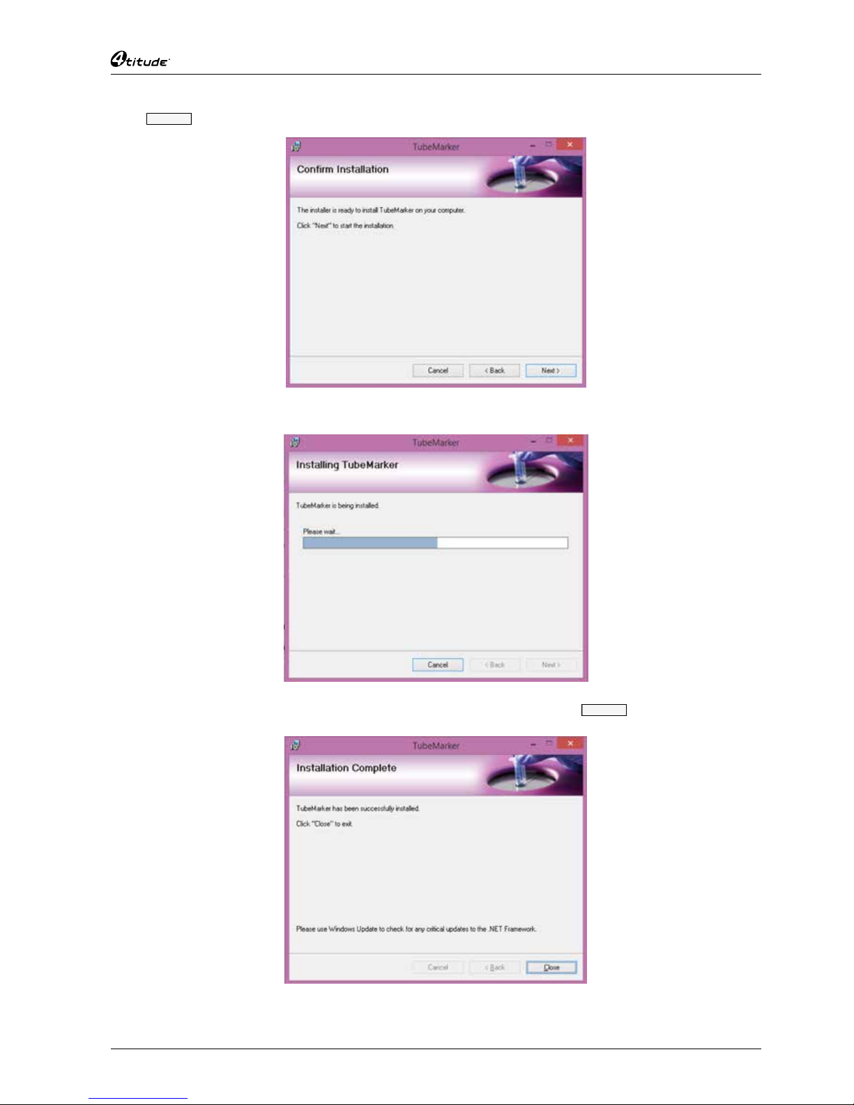
2 Software Installation........................................................................................................................8
3 Hardware Installation ....................................................................................................................10
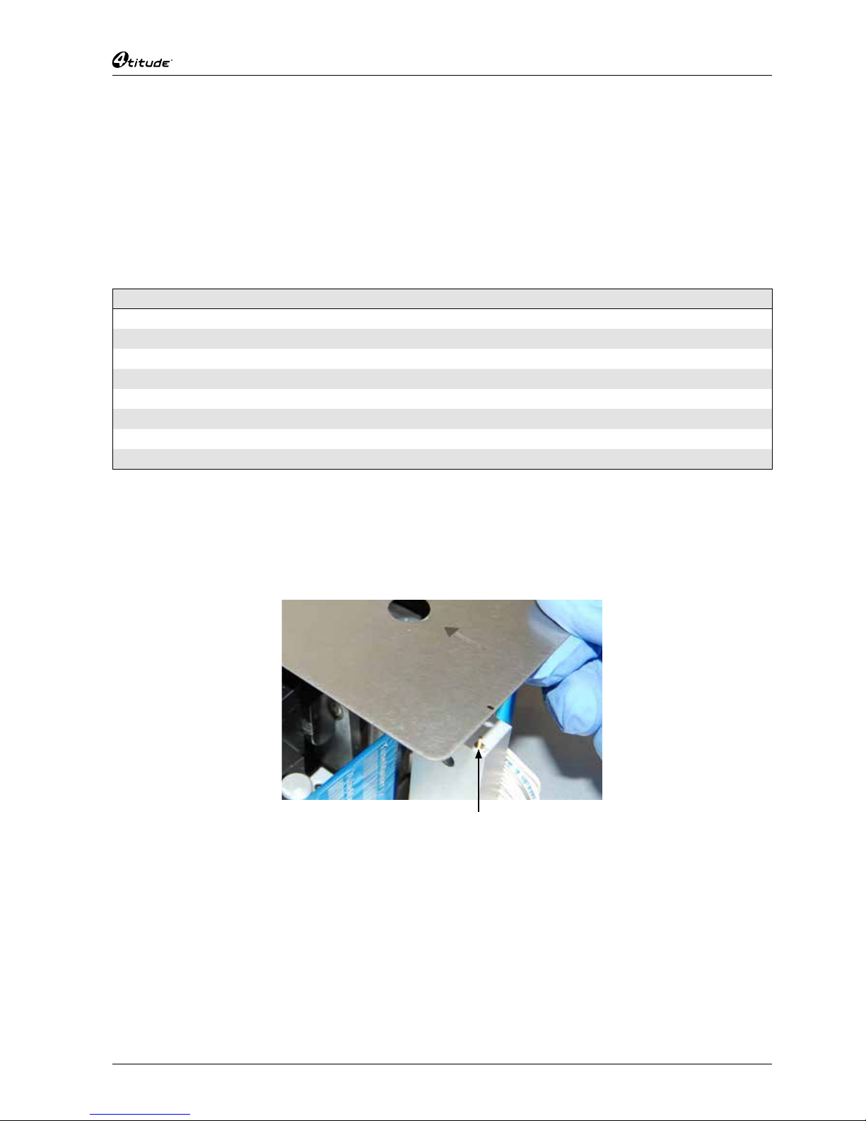
3.1 How to Install Ribbon for Printing ………………………………………………………………………………… 10
3.2 How to Set-up Tube Support……………………………………………………………………………………… 11
3.3 How to Connect Printer to PC …………………………………………………………………………………… 15
4 Preparation for Printing ................................................................................................................16
4.1 How to Create Label Content …………………………………………………………………………………… 16
4.2 How to Enter Data into the TubeMarker™ Spreadsheet ……………………………………………………… 27
4.3 How to Set the Printer Settings…………………………………………………………………………………… 29
5 Printing Modes...............................................................................................................................34
5.1 How to Use Print Mode – All ……………………………………………………………………………………… 34
5.2 How to Use Print Mode – Selected ……………………………………………………………………………… 35
5.3 How to Use Print Mode – Single ………………………………………………………………………………… 36
5.4 How to Adjust the Ribbon during Print Mode …………………………………………………………………… 37
6 How to Print using Multiple Printers............................................................................................39
6.1 How to Connect a Printer to Software …………………………………………………………………………… 39
6.2 How to Print using Multiple Printers ……………………………………………………………………………… 41
6.3 How to Disconnect a Printer from Software …………………………………………………………………… 42
7 Maintenance / Cleaning the Printhead..........................................................................................43
8 Error Messages / Troubleshooting ...............................................................................................44
8.1 Error Messages …………………………………………………………………………………………………… 44
8.2 Troubleshooting …………………………………………………………………………………………………… 44
9 AppendixA:TechnicalSpecications .........................................................................................46
10 Appendix B: Accessories / Ordering Information .......................................................................47
10.1 Accessories ………………………………………………………………………………………………………… 47
10.2 Ordering Information ……………………………………………………………………………………………… 47
11 Appendix C: Warranty ...................................................................................................................48
12 Appendix D: Shipping Instruction................................................................................................49
13 Appendix E: Disposal Information ...............................................................................................49

6
TubeMarker™ 2
TubeMarker™ 2, Operation Manual V2.0
1 TubeMarker™ 2 Introduction
1.1 The Instrument
The TubeMarker™ 2 allows printing directly onto the surface of of a wide range of tubes including PCR, centrifuge
and cryogenic vials from 0.2 – 50 ml in volume, limiting need and use of sticky labels or marker pens. Markings are
resistant to ethanol, isopropanol, water, DMSO, liquid nitrogen and mechanical stress. The prints are also stable
over a wide temperature range (-196°C to 100°C). Markings do not stain your hands when touching the tubes.
Note: Resistance varies between ribbon colours. Please refer to the TubeMarker™2 website on www.4ti.co.uk for
an overview chart of ribbon resistance & compatibility.
Ourlabeldesignsoftwaregivestheusercompleteexibilitywhencreatingtheirlabellayout.Eachpieceofdata,
beittext,barcodesorgraphiclescanbeplacedindependentlyofoneanother.Dependingontheprintingneeds,
this ensures the correct data is called upon for each cell or emphasis is given to the most important information.
Theinstrumentalsoprintslinearbarcodesand2Dcodesinvariousmodulesizesandgraphicles(.bmp,.jpg,.gif,
.png) such as company logos. Print orientation can be set within 360°.
1.2 Package Contents
• TubeMarker™ 2 (Product code 4ti-0680-1)
• 3xTubeAdapters
Tube Adapter Hole Diameter Product Code
Tube Adapter for 1.5 ml/2 ml tubes 11.5 mm 4ti-0681
Tube Adapter for 2D cluster tubes 8.5 mm 4ti-0683
Tube Adapter for cryo tubes 12.7 mm 4ti-0684
• AC adapter 18W 18VDC (input 100-240VAC)
• 7 mm magnetic pole adapter
• USB A-B cable
• 50x2mlpolypropylenetubes(asofserialnumber001-000387)
Note: For printing optimisation only. The smooth surface of the tubes will give best printing results which will
serve as a reference for printing optimisation of other tubes.
• Operation manual
• Shipping safety instruction
• USB Flash Drive

7
TubeMarker™ 2
TubeMarker™ 2, Operation Manual V2.0
1.3 TubeMarker™ 2 Parts
1.3.1 TubeMarker™ 2 External Parts
TubeMarker™ 2 front
LCD display
Top cover
Tube adapter
TubeMarker™ 2 back
Keyboard connector (USB / A)
PC connector (USB / B)
DC power connector
1.3.2 TubeMarker™ 2 Internal Parts
Sled Solenoid
Adjustable
pivot point
Ribbon
tensioner
Un-printed
ink ribbon
Spool locking
cap
Printed
ink ribbon
Adjustable
support
base knob
Dust collector
Printhead
Adapter guide pin
Tube
sensor

8
TubeMarker™ 2
TubeMarker™ 2, Operation Manual V2.0
2 Software Installation
Supplied with the TubeMarker™ 2 is a USB stick containing a folder to the software installer. Within this folder are
twoles:
• TubeMarker™ Installer (Windows Installer package .msi)
• Set-up(Application.exe)
To install the software, you must execute the installer le. Follow the steps below to install your new
TubeMarker™ software.
Note: Both the installer and set-up les must be located in the same le space for installation to be successful.
4titude recommends you run the installer directly from the USB stick.
Double click on the Installer.
The following message will appear. Upon reading the disclaimer, Click
Next >
to conrm you are happy to
proceed with installing TubeMarker™.
Select a destination folder and click
Next >
.
Note: An option to install for all users of the PC or just the one user can also be decided upon at this stage.
The installer is now ready to install TubeMarker™ on to the PC.

9
TubeMarker™ 2
TubeMarker™ 2, Operation Manual V2.0
Click
Next >
and installation will begin.
The following screen will appear displaying the installation progress.
The following screen will appear to show installation is now complete. Click
Close
to exit and complete
installation.
A shortcut to the software application will automatically be saved to the computers desktop. You are now ready to
executetheTubeMarker™software.

10
TubeMarker™ 2
TubeMarker™ 2, Operation Manual V2.0
3 Hardware Installation
3.1 How to Install Ribbon for Printing
Ink ribbon, glossy side
Ink ribbon, ink side
Ink ribbon
Drive shaft
Spool locking cap
Where possible gloves should be worn when installing the ribbon. This will ensure ink is not removed by the heat
emittedfromyourngers.
Open the top cover of the printer.
Remove the spool locking cap.
Insert the ink ribbon on the right-hand drive shaft. Make sure that the pin at the base of the drive mechanism shaft
goes into the slot on the ink ribbon core. Check that the core goes all the way down and there is no gap between the
bottom of the ribbon and the base of the drive mechanism.
Thread the ink ribbon through the path highlighted by the red line in the picture above.
Inserttheemptyinkribboncoreontotheleft-handdriveshaft.Ensuringtheslotinthecoreisushoverthepin
at the base of the shaft. Use thin adhesive tape to attach the ribbon to the empty ink ribbon core. Make sure that
the lower edge of the ink ribbon is as close to the black drive mechanism as possible and that it is not wrinkled.
Lock the spool and ribbon in place by screwing the spool locking cap down, this will help to align the ribbon.
Turn the drive mechanism and core clockwise until the start of the ink ribbon is on the core. If necessary, turn the
right hand side ink ribbon roll clockwise to tighten the ribbon as shown in the picture above.
Close the top cover and proceed to section 3.3. The TubeMarker™ 2 will carry out a calibration procedure at
startup.
Ifstartupisinterruptedtheunitwillauto-calibratebeforetherstprint.
Note: The glossy side of the ink ribbon should be against the printhead, otherwise the printhead might be damaged
when used.
Avoid touching the unused area (between the printhead and right-hand side roll holder) of the ink ribbon with bare
hands. Any dirt or grease on the ink ribbon will reduce the print quality.

11
TubeMarker™ 2
TubeMarker™ 2, Operation Manual V2.0
3.2 How to Set-up Tube Support
3.2.1 Selecting and Installing Tube Adapter
The TubeMarker™ 2 delivery package contains tube adapters for 1.5 ml / 2 ml tubes (4ti-0681, hole diameter
11.5 mm), 0.5 ml PCR and 96 racked 2D storage tubes (4ti-0683, hole diameter 8.5 mm) and cryo tubes (4ti-0684,
hole diameter 12.7 mm).
To print on tubes that are not supported by the standard adapters please refer to our website www.4ti.co.uk to see
the latest additions to the TubeMarker™ 2 portfolio. The tube adapter is selected according to the tube diameter.
TubeMarker™Tube Adapter Hole Diameter Product Code
Tube Adapter for 1.5 ml / 2 ml Tubes 11.5 mm 4ti-0681*
Tube Adapter for 2D Cluster Tubes 8.5 mm 4ti-0683*
Tube Adapter for Cryo Tubes 12.7 mm 4ti-0684*
Tube Adapter for 2 ml Screw Cap Tubes (10 mm Diameter) 10.4 mm 4ti-0685-1
Tube Adapter for 15 ml Tubes 18 mm 4ti-0685-2
Tube Adapter for 50 ml Tubes 30 mm 4ti-0685-3
TubeAdapterforMatrixTubes 8.2 mm 4ti-0685-4
Tube Adapter for 0.2 ml Tubes 6.4 mm 4ti-0685-5
*These items are included with the TubeMarker™ 2 (Code 4ti-0680-1)
Tubes without a collar will be supported from the bottom via an adjustable adapter. They will also be aligned with
the print head from the top via an adapter plate.
Tubeadaptersfortubesnotttingtoanyoftheexistingadaptersareavailableonrequest.Pleasecontact4titude®
Tube adapter guide pin
Insert the tube adapter on the sled as shown in the picture above. Check that the plate guide pin slots into the
small hole in the tube adapter.

12
TubeMarker™ 2
TubeMarker™ 2, Operation Manual V2.0
3.2.2 Setting Adjustable Support Platform
Housed within the TubeMarker™ 2 unit is an adjustable support platform from which tubes without a lip or collar
can be fully supported. Integrated within the support platform is a magnet which attracts and stabilizes the
magnetic pole attachment used to support tubes of less than 65 mm in length and do not have a collar or lip. The
magnet within the support platform has been designed and positioned in such a way to help users perfectly locate
the pole attachment and eliminate misalignment against the printhead and sled; which could potentially damage
these components.
Open the top cover and remove the adapter if applicable.
To raise the support platform turn the knob clockwise. Turning anti-clockwise will lower the platform.
Adjustable tube
support platform
knob
Tube support
platform
To perfectly optimize print results for your tube(s), you may need to adjust the pivot point of the sled to even out
pressure across the whole tube surface area, see section 3.2.4. Additionally, you may also require the use of the
7 mm magnetic pole attachment. See below for details how to correctly position the attachment.
3.2.3 Using Magnetic Pole Adapter
Whilst connected to the software with cover closed, go to Printer settings manager in bottom left corner of home
screen. Select
Sled
tab and use the up arrow
▲
toopenupthesled.Thiswillgiveyouextraroomtomaneuver
the pole attachment. Open the cover of the unit and remove the tube adaptor to place the pole attachment.
The attachment should be placed in such a way that is fully supportive to the tube you wish to print onto. Once
positioned where you think is optimal, shut the cover and close the sled by using the down arrow
▼
within the
sled tab; leaving enough room to insert the tube for printing onto.

13
TubeMarker™ 2
TubeMarker™ 2, Operation Manual V2.0
Insertthetubeandclosethesledfurthersothetubeislockedinposition.Youmayneedtomakeneadjustments
to tube platform height and pole attachment to optimise the printed label position. Ensure there is no pressure
coming from the sled when making these adjustments.
In other instances where the tubes are larger and more susceptible to falling over, 4titude®recommends the use
of an adapter plate to align the tube against the printhead and sled. This will alleviate any possibility of the tube
dropping into the unit after a print has been made.
If the tube is over 65 mm in length, there is no need for the pole attachment.
Note: Switch tube lift OFF in the TubeMarker™ printer settings tab for adaptors without a lift design or for tubes
without a cap or collar.

14
TubeMarker™ 2
TubeMarker™ 2, Operation Manual V2.0
3.2.4 Setting the Sled Pivot Point
To improve the overall print quality, users have the ability to adjust the position of the sled’s pivot point, increasing
the surface area of the tube in which pressure is applied. This is particularly useful for larger tubes or those which
arenotprintingfullynearthebaseofthetube.Thepivotpointcanonlybeloweredtoamaximumof14mmbelow
the default position. Follow the step-by-step guide below for how to effectively utilize the adjustable pivot point.
Open the top cover and remove the adapter (if applicable).
Takethe2.5mmhexkeyprovidedandadjusttheheightofthepivotpoint.Tolowerthepivotpointturnthehex
key clockwise; turning anti-clockwise will raise the pivot point.
For best results, you want to adjust the pivot point so it is applying pressure to the centre or just below the centre of
the tube you are printing on. The pivot point is located in the middle roller bearing of the top set of 3 roller bearings,
as shown in the photo below.
Note: DO NOT raise the pivot point above the default position. Default position is ush with the top of the sled.
Hexkey
Pivot point ruler
Pivot point
Pivot point ruler
Once you are happy with the pivot point positioning, replace the adapter suitable for the tube(s) you wish to print
onto and close the top cover. Make a note of the pivot point position by referencing the sled ruler.
For tubes that do not have a lip or collar, please refer to section 3.2.2.

15
TubeMarker™ 2
TubeMarker™ 2, Operation Manual V2.0
Seebelow,examplesofprintswhichwereprintedwiththepivotpointatdefaultpositionandagainwiththepivot
point adjusted to the centre of the tube. The print quality has drastically improved and important label data hasn’t
been lost as a result of the lowered pivot point.
Pivot point default
Pivot point 10 mm lower
3.3 How to Connect Printer to PC
Please check the following items before connecting the power source:
• There is no tube inside the TubeMarker™ 2
• The ink ribbon is inserted correctly
• The tube adapter is inserted correctly
• The TubeMarker™ 2 top cover is closed
Connect the DC power source plug to the connector shown in section 1.3.1.
TheTubeMarker™2willcarryoutacalibrationprocedureatstartup.Waitforcalibrationtonishbeforeproceeding.
Ifcalibrationisinterrupteditwillauto-calibrateoncetherstprintistriggered.Alternatively,youcanrestartthe
TubeMarker™ 2 by disconnecting and reconnecting the power supply.
ExecuteTubeMarker™2software!

16
TubeMarker™ 2
TubeMarker™ 2, Operation Manual V2.0
4 Preparation for Printing
4.1 How to Create Label Content
4.1.1 How to Set the Tube Label Dimensions
In order to set the optimum tube label dimensions, ensuring all label content is printed onto the tube being used,
youmustrstmeasureyourtubetondtheheightanddiameterparameters.
Themaxlabelheightisspeciedaccordingtothemeasurementofthestraightpartofthetube.Thisisbetween
thecapandtheconicalpartofthetube,asshownbelow.Themaximumprintingheightis40mm.Fortubesthat
exceed40mminlength,labelheightsshouldbesetto40mm.
Themaxlabelwidthisspeciedaccordingtothediameterofthetubebeingused.Whateverthediameterisofthe
tube, this will be converted in to its measurement as a circumference. This ensures the end of the label will not
overlap the beginning of the label.
Note: The actual tube dimensions specify the MAX label dimensions.
Example Tube Dimensions
Tube Type and Volume Tube Height Tube Diameter
0.5 ml PCR Tube 14 mm 8 mm
1.4 ml 96 Racked Storage Tube 35 mm 8 mm
1.5 ml Microcentrifuge Tube 18 mm 11 mm
2.0 ml Microcentrifuge Tube 30 mm 11 mm
1.8 ml Cryo Tube 25 mm 12 mm
15 ml Centrifuge Tube 40 mm 16 mm
50 ml Centrifuge Tube 40 mm 28 mm
Inputting these values into the software, is done according to the following:
Start by accessing the
Designer
tab on the main software screen and collapse the Cell properties by clicking the
icon.
This will reveal the
Tube
,
Layout
and
Print
tabs.
For enhanced accessibility go to
View
>
Designer
. This will open the
Designer
tab in a separate pop-out
window making placement of Cells and overall label design easier to manage.
To set the tube label dimensions, click on the
Tube
tab.

17
TubeMarker™ 2
TubeMarker™ 2, Operation Manual V2.0
Setting the Height and Diameter value can be done in three ways:
1. By highlighting and typing in the actual number
Or
2. By clicking on
▲
or
▼
. Value is adjusted in 1 mm increments/decrements.
Or
3. By using the slider; this will adjust the dimension in 1 mm increments/decrements.
Oncethetubeparametershavebeenset,yourlabelformatwillchangetorepresentthese.Twoexampleshave
been shown below:
Example - Label format for 1.5 ml Microcentrifuge Tube (4ti-0797)
Example - Label format for 2.0 ml Microcentrifuge Tube (4ti-0798)
You can createtubepresetprolesandsavethemtoadrop-downmenuforeasyaccess.

18
TubeMarker™ 2
TubeMarker™ 2, Operation Manual V2.0
Toaccessthetubepresetproles,ticktheUse Tube Presetbox
The following menu will appear
Added as defaults to the Tube Preset menu are 8 compatible Brooks tubes.
You can add to this list by clicking on
Create
.
You will then be able set the Diameter and HeightparametersandeditthetubeproleName.
Click
OK
toconrmandsavesettings.
OnceatubeproleiscreatedyouwillbeabletoEdit or Remove it from the list.

19
TubeMarker™ 2
TubeMarker™ 2, Operation Manual V2.0
4.1.2 How to Create Text Cells
Onceyourlabellayouthasbeensetyoucanbeginllingitwithdata.Ifyouwishtomakeyourdesignarealarger,
go to
View
>
Designer
.Thiswillpopthescreenouttoaseparatewindow,allowingyoutomaximisetheview.
Within the Designer click on the
AddText
button.Thiswillplacean8x8mmCellinthetopleftcornerof
the label.
Go to the
Layout
tab, here you will be able to set the following parameters:
Font (all TrueType fonts), Weight (Regular, Bold and Heavy), Text size (4 to 64), Angle of text (360°), Alignment
of text (horizontal and vertical placement), Wrap(NoWrap,WrapandWrapWithOverow)andText (Cell content
entry).
Note: A visual representation of the Cell size and placement is shown via the X and Y axis.
To alter the width, length or position of the Cell, see section 4.1.8.
ToeditthetextintheCell you can do so in two ways:
1. BymanuallytypingintextviatheTextCellwithintheLayouttab.Seesection4.1.6.
Or
2. BylinkingtheCelltoaspeciedcolumnintheDataSpreadsheet.Seesection4.1.7.

20
TubeMarker™ 2
TubeMarker™ 2, Operation Manual V2.0
4.1.3 How to Create Linear Barcode Cells
There are four variations of linear barcode to choose from: Code_128, Code_93, Code_39 and EAN_8 with
module sizes ranging from 125 µm to 375 µm.
Within the
Designer
click on
AddLbc
.Thiswillplacean8x8mmCellinthetopleftcornerofthelabel.
Go to the
Layout
tab, here you will be able to set the following parameters:
Angle of barcode (360°), Alignment of barcode (horizontal and vertical placement), Stretch (Fill, Uniform, None
and UniformToFill), Module Size (125 µm, 250 µm and 375 µm), Format (Code_128, Code_93, Code_39 and
EAN_8) and Text (code content entry).
Note: A visual representation of the Cell size and placement is shown via the X and Y axis.
To alter the width, length or position of the Cell, see section 4.1.8.
To edit the barcode type, select from the Format drop down menu.
To edit the module size, select from the Module Size menu.
ToeditthetextintheCellyoucandosointwoways:
1. BymanuallytypingintextviatheTextCellwithintheLayouttab.Seesection4.1.6.
Or
2. BylinkingtheCelltoaspeciedcolumnintheDataSpreadsheet.Seesection4.1.7.

21
TubeMarker™ 2
TubeMarker™ 2, Operation Manual V2.0
4.1.4 How to Create Datamatrix Cells
There are two variations of Datamatrix ECC200 to choose from: Square and Rectangular. Module sizes range
from 125 µm to 375 µm.
Within the
Designer
click on
AddGfx
.Thiswillplacean8x8mmCellinthetopleftcornerofthelabel.
Go to the
Layout
tab, here you will be able to set the following parameters:
Angle of Barcode (360°), Alignment of barcode (horizontal and vertical placement), Stretch (Fill, Uniform, None
and UniformToFill), Module Size (125 µm, 250 µm and 375 µm), Quiet Zone (0-32), Text (code content entry)
and Shape (Square and Rectangle).
Note: A visual representation of the Cell size and placement is shown via the X and Y axis.
To alter the width, length or position of the Cell, see section 4.1.8.
To edit the barcode shape, select from the Square or Rectangle from the Shape drop down menu.
To edit the module size, select from the Module Size menu.
ToeditthetextintheCellyoucandosointwoways:
1. BymanuallytypingintextviatheTextCellwithintheLayouttab.Seesection4.1.6.
Or
2. BylinkingtheCelltoaspeciedcolumnintheDataSpreadsheet.Seesection4.1.7

22
TubeMarker™ 2
TubeMarker™ 2, Operation Manual V2.0
4.1.5 How to Create Graphic Files
Therearefourgraphicletypesthatcanbeimportedintothesoftware:.bmp, .jpg, .gif and .png. Optimisation of
thegraphiclesshouldbedonepriortoimportation.
Youshouldaimtogetyourgraphicassmallaspossible,withoutpixelatingthecontent.Ifthegraphicsizeneeds
tobereduced,keepinmindthat1pixelcorrespondsto0.125mm.Forexample,apictureof100x100pixelsis
12.5mminwidth.Re-sizingofthegraphicleneedstobedoneinanexternalprogram.
Within the
Designer
click on
AddLbc
.Thiswillplacean8x8mmCellinthetopleftcornerofthelabel.
Go to the
Layout
tab, here you will be able to set the following parameters:
Angle of Graphic (360°), Alignment of Graphic (horizontal and vertical placement), Image (Load), Stretch (Fill,
Uniform, None and UniformToFill), Process (Dither, Threshold).
Note: A visual representation of the Cell size and placement is shown via the X and Y axis.
Click on
Load
undertheImageheader,leexplorerwillopen.
LocateyourgraphiclewithintheFileExplorerandclick
OK
.
To alter the width, length or position of the Cell, see section 4.1.8.
To enhance the graphic process, select from the Threshold from the Process drop down menu.
Table of contents
Other 4titude Laboratory Equipment manuals
Popular Laboratory Equipment manuals by other brands

BioLAB
BioLAB BFSD-502 Operation manual

Hitachi
Hitachi CR22N instruction manual

Endress+Hauser
Endress+Hauser Liquistation CSF48 Operation and setting

Thermo Scientific
Thermo Scientific Ion GeneStudio S5 user guide

Henry Schein
Henry Schein Maxima Turbo Instructions for use

Specac
Specac Storm 10H user manual