FRIMETAL PI Series User manual


SERIE PI
Evaporadores comerciales con ventiladores de 1~230 V.
Se fabrican en dos versiones, normal Ncon motores de 4 polos
y silenciosa Scon motores de 6 polos para aplicaciones que
requieran bajo nivel sonoro o bajo caudal de aire.
Para temperaturas altas (PIA), medias (PIM) y bajas (PIB).
La carrocería es de aluminio y acero lacado en blanco con
resina de poliéster de gran robustez y elevada resistencia a la
corrosión.
Este Manual es válido para la versión básica y para evapora-
dores con las siguientes opciones:
- Desescarche eléctrico.
- Circuito para agua glicolada u otros refrigerantes líquidos.
- Diferentes materiales como aletas de cobre o tubos de
acero inoxidable.
Para evaporadores con opciones o características diferentes
de las anteriores como ventiladores especiales, conexiones
de resistencias no estándar, dimensiones especiales u otras,
algunas partes de este Manual pueden no ser aplicables.
En este Manual se explica la colocación e instalación del eva-
porador y se describen las principales operaciones de man-
tenimiento y limpieza.
Es necesario que el instalador siga los pasos, las recomen-
daciones y advertencias dadas para asegurar un óptimo fun-
cionamiento del evaporador dentro de la instalación de frío.
COLOCACIÓN EN LA CÁMARA
El evaporador se entrega atornillado sobre un palé y embala-
do mediante cinta de plástico y jaula de madera. Para colo-
carlo en la cámara hay que seguir los pasos descritos a con-
tinuación:
1 Desmontar la jaula de madera y quitar el plástico que recu-
bre el evaporador.
2 Colocar espárragos roscados de fijación de 10/12 mm. en el
techo a las distancias de los anclajes del evaporador con sufi-
ciente resistencia. Consultar las dimensiones y pesos al final
del Manual. Tener en cuenta los incrementos de peso del
refrigerante y escarcha, así como la fatiga por vibraciones.
2
PI SERIES
Commercial evaporators of dual air discharge with axial fan of
1~230V.
They are manufactured in 2 versions, normal Nwith 4 pole
motors and silent Swith 6 pole motors for those applications
requiring low sound level and air flow.
For high (PIA), medium (PIM) and low (PIB) temperatures.
The casing is made of aluminium and galvanised steel pain-
ted with a white polyester coating providing great strength
and high corrosion resistance.
This Manual is valid for the basic version and for evaporators
with the following options:
- Electrical defrosting
- Circuits for glycol water or other liquids
- Different materials as copper fin or stainless steel tubes.
Some parts of this Manual may not apply to evaporators with
options or characteristics different from the above such as
special fan motors, heaters with non-standard connection,
special dimensions or others.
This Manual explains all the necessary steps for the unpac-
king, placing and installation of the evaporator and describes
the main procedures for maintenance and cleaning.
It is necessary for the installer to follow the steps, the advice
and recommendations given in order to ensure an optimal
operation of the evaporator within the cold installation.
PLACING IN THE COLD ROOM
The evaporator is supplied screwed over a wooden pallet and
packed by means of a plastic film and a wooden crate. For pla-
cing the unit on the ceiling of the working room it is compulsory
to follow the instructions given below.
1 Remove the wooden crate and the plastic cover from the eva-
porator.
2 Place screws of 10/12mm diameter on the ceiling with suffi-
cient resistance and at the distance between the anchorage
points of the evaporator. Consult the dimensions and weights
in this Manual. Take into account the weight added of refrige-
rant and frost, as well as the fatigue caused by vibrations.

3
¡PRECAUCIÓN!
- Para garantizar una perfecta sustentación es necesario uti-
lizar todos los anclajes del evaporador.
- Es conveniente la utilización de guantes protectores en la
manipulación del evaporador.
5 Colocarlo ligeramente inclinado hacia el desagüe regulan-
do la altura de los soportes.
6 Respetar las distancias mínimas indicadas a las paredes.
Si la unidad incorpora desescarche eléctrico, por el extre-
mo donde se introducen y sacan las resistencias eléctricas
ha de dejarse una distancia aproximada de L-200 a la
pared con el fin de posibilitar su sustitución.
7 Realizar las conexiones frigoríficas según dibujo. El tubo
de desagüe debe tener una ligera caída. Es conveniente
colocar un sifón para evacuar la suciedad.
!
3 Elevar el evaporador mediante una carretilla auxiliar y ator-
nillarlo al techo.
4 Quitar los tornillos que unen las patas soportes y el eva-
porador, retirar las patas y el palé.
3 Lift the evaporator, fixed on the pallet, by means of a for-
klift and screw it on the ceiling.
4 Unscrew and remove both the wooden pallet and the
transporting legs from the evaporator.
WARNING!
- In order to guarantee a perfect anchoring it is necessary to
use all the fixture brackets available on the evaporator.
- It is advisable to use protective gloves while handling and
anchoring the evaporator.
5 Place the unit with a slight inclination towards the drain
hole adapting the position of the supporting brackets.
6 Respect the minimum distances indicated to the walls. If
the unit incorporates electric defrosting, an approximate
distance of L-200 to the wall must be kept on the side
where the heating elements are removed and introduced to
allow their replacement.
7 Make the refrigerant connections according to the dra-
wing. The draining pipe must have a slight slope. It is advi-
sable to place a siphon to evacuate the dirt.
!
8 Distribuir los evaporadores regularmente, de manera que a
cada evaporador le corresponda enfriar la misma porción de
cámara.
8 Place the evaporators in a regular pattern so that every unit
gets to cool the same share of the room.

4
CONEXIONES FRIGORÍFICAS
¡IMPORTANTE!
El evaporador se suministra sellado y con aire seco a presión
en el interior de la batería. El instalador puede así comprobar
que el aparato le llega en perfectas condiciones de estanquei-
dad. En el caso de que no hubiera aire en el interior, ¡NO CON-
TINUAR CON LA INSTALACIÓN DEL EVAPORADOR! y poner-
se en contacto con el Servicio Técnico de FRIMETAL.
Los pasos a seguir son:
1 Aflojar los tornillos y quitar la tapa lateral.
2 Quitar el tapón y el obús de la válvula situada en el colector
para sacar todo el aire del interior. Volverlos a colocar pos-
teriormente.
3 Cortar el extremo del colector y del distribuidor de líquido
con un cortatubos.
REFRIGERANT CONNECTIONS
IMPORTANT!
The evaporator is supplied with its circuit sealed and with pres-
sured dry air inside the coil. In this way the installer can be sure
that the unit reaches the client in perfect condition and leak
free. In case there were no air inside, DO NOT CONTINUE
WITH THE INSTALLATION! and get in contact with the
Technical Service of FRIMETAL.
To make the connections follow these steps:
1 Loosen the screws and remove the lateral plate
2 Unscrew the stopper and the valve core placed in one of the
headers to let all the air out. Replace them afterwards.
3 Cut the butt ends of the header and liquid distributor with a
pipe cutter.
Si el aparato incorpora la opción “Circuitos para agua glicola-
da u otros refrigerantes líquidos”, entonces llevará dos colec-
tores del mismo diámetro en lugar de colector y distribuidor.
Por lo demás, la forma de realizar las conexiones frigoríficas en
estos modelos es igual a la de los modelos estándar.
If the unit incorporates the option “Circuits for glycol water or
other liquid refrigerants”, it will have two headers of the same
diameter instead of header and liquid distributor. Apart from
that, the way of making the refrigerant connections on these
models is the same as for the Standard models.
Cuando la temperatura de evaporación sea menor de 0ºC, la
puerta de la cámara debe estar lo más alejada posible del eva-
porador para evitar que la humedad del género introducido y la
procedente del exterior acceda directamente al aparato y
forme placas de hielo, lo cual perjudica el rendimiento frigorífi-
co y puede provocar daños irrevesibles en los tubos de la
batería, dañándola irreversiblemente.
¡IMPORTANTE!
En este tipo de evaporadores, al ser impulsado el aire a través
de la batería hacia el exterior, puede haber arrastre de gotas de
agua procedentes de la condensación del aire que salgan pro-
yectadas a la cámara.
Para evitar esta circunstancia, se aconseja seleccionar mode-
los de la gama silenciosa S, que llevan ventiladores de menor
velocidad (900 rpm) y bajo caudal de aire. Como complemen-
to se pueden colocar unos deflectores a lo largo de las baterí-
as por la zona de salida del aire que recogen las gotas pro-
yectadas. Para más información consultar al Servicio Técnico
de FRIMETAL.
Whenever the evaporating temperature is under 0ºC, the
room door must be as far away as possible from the evapo-
rator in order to prevent the humidity coming from the ente-
ring goods and from the outside getting into the unit forming
ice blocks, which reduce the cooling efficiency and may
damage the coil tubes beyond repair.
IMPORTANT!
In these type of unit coolers, as the air is expelled through the
coil to the outside, drops of condensed water may be carried
away and projected to the cold room.
To avoid this circumstance, it is advisable to select models of
the silent range S with fan motors of lesser speed (900 rpm)
and low air flow. As a complementary measure, some deflec-
tors may be placed along the coils at the air outlet area to
collect and take back the drops projected outside the coil.
Consult the Technical Department of FRIMETAL for more infor-
mation.

5
4 Soldar el colector a la línea de aspiración colocando un
trapo húmedo en el tubo del colector para evitar la transmi-
sión de calor hacia la batería.
5 Soldar el tubo de entrada del distribuidor de líquido a la sali-
da de la válvula de expansión. Colocar un trapo húmedo
alrededor de la válvula de expansión para evitar que se dañe
durante la soldadura y seguir las instrucciones dell fabrican-
te de la válvula para la conexión al distribuidor, la colocación
del bulbo y de la línea de igualación de la presión. En ambos
casos utilizar soldadura autógena de propano y oxígeno con
varilla de aportación de cobre, fósforo y plata.
El colector y el distribuidor así como las soldaduras de cobre
son las partes más delicadas del evaporador. Para evitar que
como consecuencia de una incorrecta realización de las cone-
xiones la batería resulte dañada, con el peligro de que se pro-
duzcan fugas del refrigerante, es absolutamente necesario
tener en cuenta las siguientes recomendaciones:
¡PRECAUCIÓN!
- Al hacer las conexiones, no forzar el colector ni el distribui-
dor para no provocar fugas o deterioros en las soldaduras.
- No aportar excesivo calor al soldar y no dirigir la llama del
soplete hacia la batería para no dañarla.
- Evitar a toda costa la presencia de humedad en el interior de
las tuberías, la cual es perniciosa para todos los elementos
de la instalación de frío. El uso de nitrógeno para eliminarla
no presupone una garantía total, porque el propio nitrógeno
contiene a veces algo de humedad o porque el refrigerante
introducido posteriormente también puede llevarla en oca-
siones. En estos casos hay que utilizar filtros secadores ade-
cuados para eliminarla totalmente.
!
4 Weld the header to the suction pipe placing a damp cloth
around the header pipe to avoid the transmission of heat
towards the coil.
5 Weld the distributor inlet pipe to the expansion valve outlet.
It is also advisable in this case to place a damp cloth around
the expansion valve to avoid any damage during the wel-
ding process. In any case it is necessary to follow up the ins-
tructions given by the expansion valve manufacturer for
both the connection to the liquid distributor as well as the
placement of the bulb and the pressure equalization line. In
both cases use an autogenous welding of propane and oxy-
gen with welding rod of copper, phosphorus and silver alloy.
The header and liquid distributor as well as the copper welding
are the most delicate parts of the evaporator. In order to avoid
damage to the coil due to an incorrect installing, thus running
the risk of causing refrigerant leaks, it is imperative to take into
account the following recommendations:
WARNING!
- While making the connections, do not force either the header
or the distributor as this may deteriorate the welded joints
and cause leaks.
- Do not apply excessive heat while welding and do not point
the torch flame directly to the evaporator coil.
- Avoid at all costs the presence of humidity inside the piping,
as it is harmful for the refrigeration installation. The use of
nitrogen to dry it up does not imply a total guarantee becau-
se the nitrogen itself or the refrigerant introduced afterwards
may sometimes contain a certain amount of humidity. In
these cases proper dry filters must be used to remove it com-
pletely.
!
MODELOS CON TUBO DE ACERO INOXIDABLE
La gama PI puede fabricarse con acero inoxidable del tipo AISI
304L o AISI 316L y pueden llevar distribuidor de líquido y colec-
tor (para sistemas de expansión directa) o dos colectores (para
modelos que trabajen con líquidos o con amoniaco bombeado).
Estos modelos también se entregan con aire seco a presión en
el interior y el proceso de realización de las conexiones así
como las precauciones a tomar para una correcta instalación
son las mismas explicadas anteriormente para los aparatos
con tubo de cobre.
MODELS WITH STAINLESS STEEL TUBES
The PI series can be manufactured with stainless steel tubes
type AISI 304L or AISI 316L and may have liquid distributor
and header (for DX systems) or two headers (for units working
with liquid refrigerant or pumped ammonia).
These models are also delivered with pressured dry air inside
the coil and the process of making the connections as well as
the precautions to be taken for a correct installation are the
same explained previously for the models with copper tubes.

6
La diferencia es el tipo de soldadura a utilizar para conectar los
tubos. Se aconseja utilizar soldadura de tipo GTAW (también
conocida como TIG). Es una soldadura de arco eléctrico
mediante un electrodo de tungsteno no consumible. Para
acero inoxidable debe utilizarse corriente continua.
Para unir los tubos la soldadura a tope es la mejor opción,
empleando como aportación una varilla del mismo material
que el acero inoxidable de los tubos y usando ARGON como
gas inerte para crear una atmósfera de protección.
Los parámetros de la soldadura (diámetro y tipo de electrodo,
intensidad de corriente…) así como la técnica de soldeo
depende del espesor de los tubos, del tipo de unión y de la
experiencia del soldador.
The only difference is the type of welding for making the con-
nections of the piping. It is advisable to use a GTAW (also
known as TIG) electric arc welding with a non-consumable
tungsten electrode. For stainless steel, a DC-straight polarity
electric current must be used.
To connect the tubes (a butt joint type is the best choice), use
a filler rod of the same material than the stainless steel of the
base metal and a shielding inert gas, generally ARGON, to cre-
ate a protective atmosphere.
The parameters of the welding (diameter of the electrode,
current amperage…) and the welding technique depends on
the tube thickness, the type of joint to be made and the expe-
rience of the welder.
CONEXIÓN DE LOS VENTILADORES
Los ventiladores son helicoidales con motor de rotor externo
1~230V, IP-44. Las características vienen especificadas en la
etiqueta del ventilador.
¡PRECAUCIÓN!
Durante las operaciones de conexión de los ventiladores ase-
gurarse de que la corriente eléctrica esté desconectada.
1-CAJA DE CONEXIÓN DEL VENTILADOR
Los ventiladores que lleva esta gama de evaporadores son de
dos diámetros diferentes: Ø 300 y 400 mm.
Cada ventilador lleva una caja de conexiones en el centro de la
rejilla y accesible desde el exterior. Van cableados de fábrica a
una caja de plástico IP-55 situada donde quedan todas las
conexiones centralizadas.
Se adjuntan los dibujos con las conexiones en las cajas de los
ventiladores con los siguientes elementos:
1 Regleta de conexiones de cuatro terminales.
2 Manguera con los cables que salen del motor.
3 Condensador del motor.
4 Manguera con 3 cables que sale hacia la caja de conexio-
nes exterior. Estos cables corresponden a la fase de línea L,
al neutro N, y al cable de conexión a tierra PE.
Este esquema de conexiones viene también en una pegatina
colocada en el interior de la tapa de la caja de conexiones de
cada ventilador.
!
FAN MOTOR CONNECTION
Axial fans with external rotor motors 1~230V, IP-44. The cha-
racteristics are specified on a label stuck on the fan motor.
WARNING!
During the fan motor connecting operation make sure that the
electric current is disconnected.
1-JUNCTION BOX ON THE FAN MOTOR
These evaporators incorporate fan motors of diameter 300 or
400 mm.
Each fan motor has an individual junction box in the centre of
the grille and accessible from the outside. The fan motors are
wired from factory to a plastic junction box IP-55 placed on one
end of the unit where all the electric connections are centralized.
Below there is a drawing of a fan motor showing the plastic
junction box in the middle with the following elements:
1 Terminal strip with 4 connections
2 Cable with the wires coming from the motor
3 Motor capacitor
4 Cable with 3 wires coming out to the external junction box.
These wires correspond to the line L, neutral N and the
ground connection PE.
The fan motor connection drawing is also displayed in a label
stuck on the inner side of each junction box lid.
!

7
2- CAJA DE CONEXIONES CENTRALIZADA
La conexión debe realizarse en la caja de conexiones a la que
se accede quitando el lateral del lado de las conexiones eléc-
tricas situado al extremo opuesto de las conexiones frigorífi-
cas. A esta caja llegan las mangueras de 3 cables (L,N,PE) de
cada ventilador.
Se adjunta el diagrama de conexión
de los motores en la caja, el cual
viene también en una etiqueta pega-
da en el interior de la tapa de la caja.
Una vez realizada la conexión, dar
corriente, comprobar que todos los
motores funcionan y que la dirección
del aire es la correcta, entrando por
los ventiladores y saliendo por las
baterías. Aunque las cajas de cone-
xiones tienen protección IP-55, para
asegurar una total estanqueidad es conveniente sellar los pren-
saestopas con masilla o silicona.
Estos ventiladores incorporan un termocontacto interno para
protección. Si un motor se calienta por mal funcionamiento o
por otra causa, al sobrepasar la máxima temperatura permiti-
da se abre el termocontacto y el ventilador automáticamente
se para. Cuando la temperatura baja, al cabo de un tiempo el
motor vuelve a funcionar.
SUSTITUCIÓN DE LOS VENTILADORES
¡PRECAUCIÓN!
Antes de empezar la sustitución del ventilador, asegurarse de
que la corriente eléctrica de alimentación a los ventiladores
está desconectada mediante un interruptor de seguridad.
Los pasos para sustituir un ventilador son los siguientes:
1 Aflojar los tornillos de la caja del ventilador situada en el
centro de la rejilla y quitar la tapa.
2 Aflojar los tornillos de la regleta y soltar los cables de la
manguera de salida.
3 Aflojar el prensaestopa, cortar las bridas de plástico y
sacar la manguera de la caja.
4 Quitar los tornillos que sujetan la rejilla a la carrocería del
evaporador. Retirar el ventilador y colocar el nuevo invir-
tiendo los pasos anteriores.
REPLACEMENT OF FAN MOTORS
WARNING!
Before starting operations to replace a fan motor, make sure
that the current line to the fan motors disconnected by means
of a security switch so as to prevent an accidental start.
The steps to replace a fan motor are the following:
1 Loosen the screws of the junction box placed in the cen-
tre of the grille and remove the lid
2 Loosen the screws on the terminal strip and release the
wires of the outlet cable.
3 Loosen the packing gland, cut the plastic ties and remove
the cable from the box.
4 Remove the screws which fix the grille to the body of the
evaporator. Remove the old fan motor and place the new
one reversing the steps mentioned above.
!!
2- CENTRALIZED JUNCTION BOX
The electric wiring must be done directly in the junction box pla-
ced on the side of the evaporator opposite to where the refrige-
rant connections are situated. This box is accessible removing
the lateral plate from the evaporator. To this box arrive the
cables with 3 wires (L, N, PE) coming from each fan motor.
Below is shown the connection dia-
gram for the fan motors. This diagram
also comes on a label stuck to the
inner side of the junction box lid.
Once the connection is made, switch
on the electric current, check that all
the fan motors turn properly and that
the air direction is correct, entering
through the fan motors and leaving
through the coils. Even though the
junction boxes have protection IP-55,
it is advisable to seal the parking glands with putty or silicone to
ensure a total waterproofing.
These fan motors have an internal thermocontact for protec-
tion. If a fan motor heats up due to malfunction or other reason,
once the maximum allowed temperature is reached, the ther-
mocontact opens and the fan motor stops. When the tempera-
ture goes down to a normal value, the thermocontact closes
and the fan motor restarts.

8
DESESCARCHE ELÉCTRICO
El desescarche eléctrico es una opción que incorpora:
1 Resistencias blindadas en acero inoxidable de 230V con
los extremos vulcanizados colocadas en el interior de la
batería y bajo la bandeja inferior de goteo.
2 Caja de conexiones a la que van conectadas las resisten-
cias. Se adjunta diagrama de conexión. Este diagrama
viene también en una pegatina adherida al interior de la tapa
de la caja de conexiones de las resistencias.
ELECTRIC DEFROSTING
The electric defrosting is an option that includes:
1 Heating elements of 230V, encased in stainless steel tubes
with both ends vulcanised distributed through the coil and
under the drain tray.
2 Junction box to which the heaters are connected. See
attached the connection diagram. This diagram may also
be found on a label stuck on the inner side of the junction
box lid.

9
SUSTITUCIÓN DE LAS RESISTENCIAS
RESISTENCIAS DE BATERÍA
1 Retirar la tapa lateral del evaporador y la tapa de la caja de
plástico de conexiones de las resistencias.
2 Aflojar los tornillos de la regleta correspondientes a la resis-
tencia a sustituir y soltar los cables.
3 Aflojar el prensaestopa y sacar los cables de la caja.
4 Enderezar los extremos de la resistencia con el fin de facili-
tar su extracción.
5 Empalmar un cable de una longitud algo mayor que la del
evaporador en cada extremo de la resistencia. Esta acción
ayuda posteriormente a la introducción de la nueva resis-
tencia.
6 Retirar la tapa lateral del lado opuesto del evaporador y
extraer la resistencia a sustituir.
7 Cortar los cables por el empalme por medio de unas tijeras
u otra herramienta de corte, retirar la resistencia vieja y unir
los cables a los extremos de la nueva resistencia.
Introducir la nueva resistencia en la batería a la vez que se tira
de los cables del extremo opuesto.
Una vez que la resistencia queda introducida en la batería, se
quitan los cables empalmados y se termina la sustitución invir-
tiendo los pasos 1 a 3.
REPLACEMENT OF HEATERS
COIL HEATERS
1 Remove the side cover from the evaporator and the heaters
junction plastic box lid
2 Loosen the screws on the strip corresponding to the con-
nections of the heater to be replaced and remove the wires.
3 Loosen the packing gland and withdraw the wires from the
box.
4 Straighten the ends of the heating element to facilitate its
removal.
5 At both ends of the heater attach a wire a bit longer than the
length of the evaporator. This helps afterwards to introduce
the new heater inside the coil.
6 Remove the side cover of the opposite side and take out the
heater to be replaced.
7 Cut the extended wires through the knot by means of a pair
of scissors or other cutting tool, remove the old heater and
tie the wires to the ends of the new heater.
Introduce the new heater in the coil and at the same time pull
from the wires at the opposite side.
Once the heater is introduced in the coil, cut and retire the
extended wires and finish the replacement by reversing steps 1
to 3.

10
RESISTENCIAS DE LA BANDEJA
Estos evaporadores llevan resistencias eléctricas en la parte
inferior, una por debajo de cada bandeja. Van sujetas
mediante unas chapas con canales por los que desliza per-
mitiendo su extracción.
Si la resistencia a sustituir está muy deteriorada se aconseja
quitar estas chapas para poder sacarla.
Los pasos a seguir para su sustitución son los mismos que los
explicados anteriormente, aunque para acceder a ellas hay
que realizar previamente el siguiente paso:
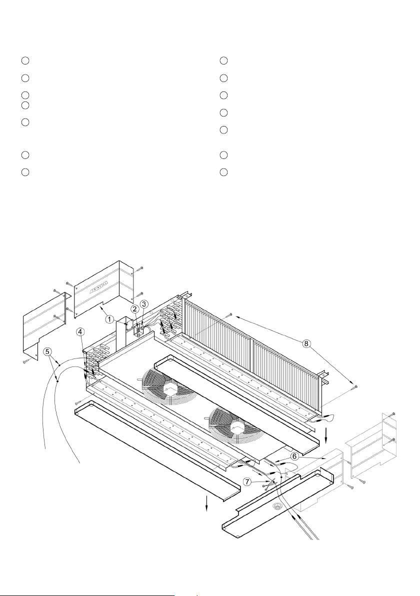
8 Quitar todos los tornillos y retirar las bandejas inferiores.
Una vez realizadas esta operación, los pasos a seguir son los
1 a 7 explicados en el párrafo anterior.
LIMPIEZA
Para la limpieza de la batería se aconseja utilizar una mezcla de
agua y un detergente específico para baterías aleteadas pro-
yectado sobre las aletas con una máquina limpiadora de pre-
sión. Después hay que eliminar el detergente proyectando de
nuevo sobre las aletas un chorro de agua pura procurando que
penetre en el interior de la batería todo lo posible para que la efi-
cacia de la limpieza sea máxima. Evitar dirigir chorros de agua
hacia los ventiladores y las cajas de conexiones eléctricas.
Para limpiar la carrocería utilizar una esponja con agua o con
un detergente muy diluido y que no dañe la pintura.
MANTENIMIENTO GENERAL
Verificar periódicamente que toda la tornillería está bien apre-
tada y en buen estado, sobre todo los anclajes del evaporador
al techo y la sujeción de las rejillas y ventiladores. Reapretarlos
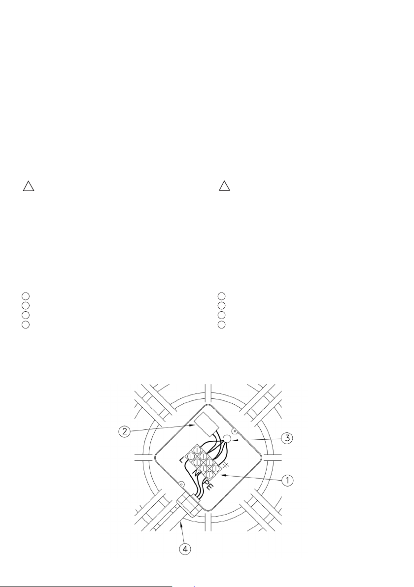
o cambiarlos en caso contrario. Comprobar que las conexio-
nes de los cables en las regletas de las cajas de conexiones
tanto de los ventiladores como de las resistencias de deses-
carche (en el caso que las lleven) no estén flojas o sueltas. En
caso contrario, reapretar los tornillos de los terminales.
Para asegurarse de que el agua no entra en las cajas, comprobar
que no estén rotas o deterioradas. Verificar la estanqueidad de
todos los prensaestopas y si fuera necesario, reapretarlos y sellar
con masilla o silicona.
ADVERTENCIAS
El evaporador es sólo un elemento en una instalación comple-
ta de frío y su funcionamiento se controla externamente. Es res-
ponsabilidad del instalador colocar los controles necesarios
que impidan que el evaporador pueda funcionar fuera de los
límites de presión y temperatura especificados en su placa de
características. Una instalación o utilización del evaporador que
no se ajuste en su totalidad a dichos límites o a lo especificado
en este Manual supone una automática anulación de la garan-
tía concedida por FRIMETAL y la exención de las responsabili-
dades que puedan derivarse. Todas las operaciones de instala-
ción y mantenimiento deben ser realizadas por personal técni-
co cualificado y se ha de tener en cuenta la normativa vigente.
Es necesario comprobar que el ambiente en el que va trabajar el
evaporador no contenga o genere sustancias corrosivas para los
materiales de que está compuesto. En caso de duda, consultar
con el Departamento Técnico de FRIMETAL las diferentes
opciones que existen en cuanto a tratamiento de protección.
En cualquier caso, la garantía nunca cubrirá los gastos ocasio-
nados por problemas de corrosión.
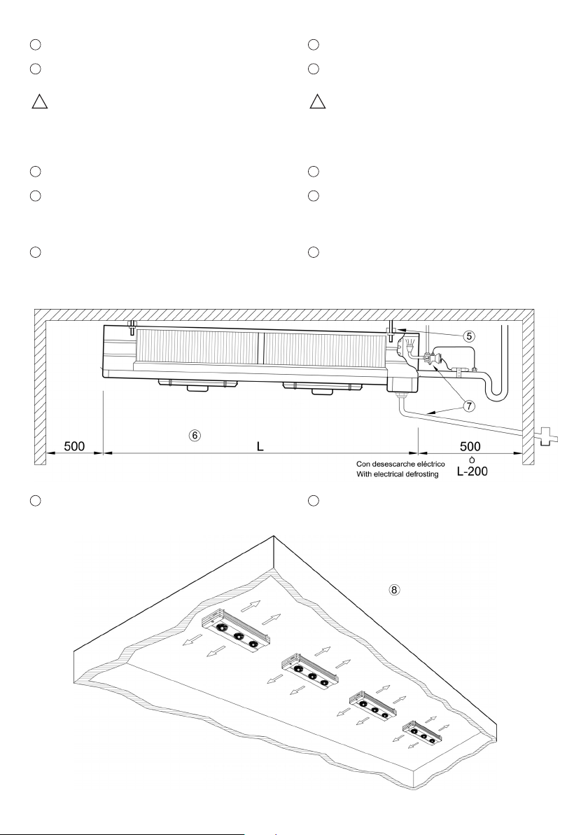
Para más información respecto de las capacidades y caracte-
rísticas técnicas, consultar en nuestro catálogo general la
gama de evaporadores PI comerciales.
En nuestra página www.frimetal.es está disponible el catálogo
general así como un programa de descarga libre de ayuda a la
selección de nuestros productos. Nos reservamos el derecho
de cualquier modificación en la especificación y características
de nuestro material, en cualquier momento y sin previo aviso.
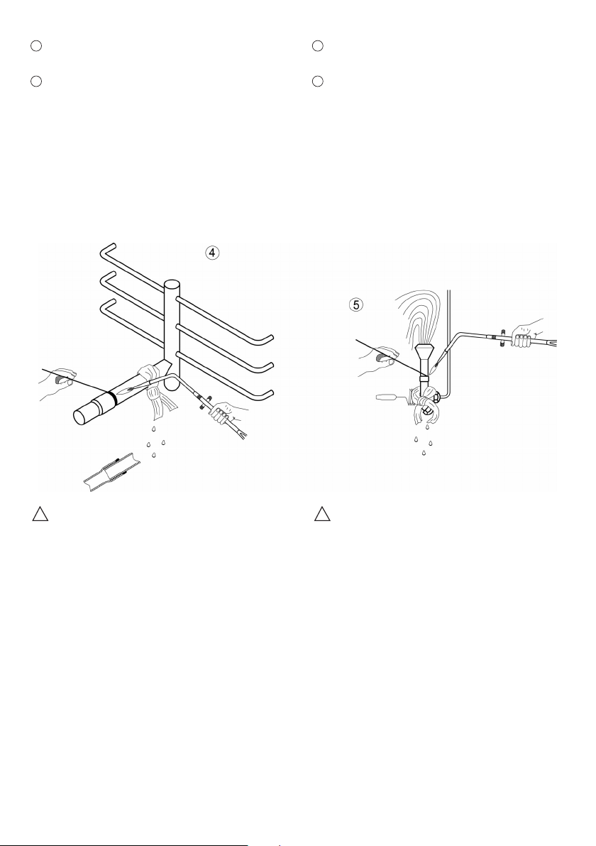
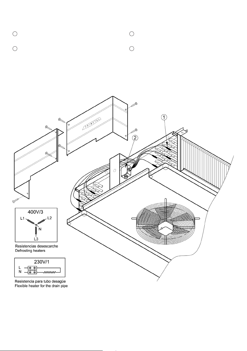
DRIP TRAY HEATERS
These evaporators incorporate electric heaters in the lower
part of the unit below the drip tray. The heaters are held to the
tray by means of plates with channels, through which the hea-
ters slide, allowing extraction.
If the heater to be replaced is very deteriorated, it is advisable to
remove these plates to extract the heater.
The steps to replace a heating element are the same explained
before for coil heaters though, to allow the access to the heater,
it is necessary previously to:
8 Remove all the screws and take away the inferior try trais.
Once the above instructions are carried out, follow steps 1 to 7
as in the previous paragraph.
CLEANING
For cleaning the coil it is advisable to use a solution of water
and a detergent specific for finned coils projected over the fins
with a pump cleaning machine. Afterwards it is necessary to
rinse the detergent projecting over the fins a water jet trying to
get the water into the coil as much as possible to optimize
cleaning. Avoid pointing the water jet to the fan motors and
the electric junction boxes.
The casing can be cleaned with a sponge with a soft solution
of water and a detergent not harmful for the paint.
GENERAL MAINTENANCE
Check periodically that all the bolts and nuts are tight and in
good condition mainly the fixations of the evaporator to the cei-
ling and the fastening of grilles and fan motors. Tighten or
replace them if needed.
Check that the connections of the wires in the terminal strips
inside the junction boxes of the fan motors and defrosting hea-
ters (in case this option is incorporated) are not loose. Tighten
the terminal screws if needed. To ensure that the water can not
get into the junction boxes, check that they are not broken or
in bad condition. Also check the waterproofing of all packing
glands and tighten and seal with putty or silicone if needed.
ADVICE
The evaporator is only one element in a complete cold installa-
tion and its functioning is controlled externally. It is the installe-
r’s responsibility to position the necessary controls to prevent
the evaporator from operating beyond the limits of pressure
and temperature specified on its data plate. Any installation or
use of the unit in conditions that do not comply entirely with the
specifications of this Manual will automatically void the gua-
rantee given by FRIMETAL and the exemption of the responsi-
bility that may result. All installation and maintenance opera-
tions must be carried out by qualified technical personnel and
abided by current standards and regulations.
It is necessary to check that the environmental conditions in
which the evaporator is going to work does not contain or gene-
rate corrosive substances for the elements of the unit. If in doubt,
consult the Technical Department of FRIMETAL about the dif-
ferent options there are as regards protective treatments. In
any case, the guarantee will never cover the expenses caused
by corrosion.
For more information regarding capacities and technical cha-
racteristics, consult our catalogues of series commercial PI
which you can request at our Commercial Department.
In our web site www.frimetal.es a general catalogue with all our
products is available as well as a free downloadable program
to help the selection of our products.
We reserve the right of any modification in the specifications
and characteristics of our material, at any time and without pre-
vious notification.

11

+34 913030426 • FAX +34 917774761
San Toribio, 6 • 28031 MADRID
1.000 - 07 - 17
Declaración de Incorporación
Declaration of Incorporation
de acuerdo a la Directiva de Máquinas 2006/42/CE del Parlamento Europeo, Anexo II B
according to the Machinery Directive 2006/42/EC of the European Parliament, Annex II B
El fabricante, The Manufacturer FRIMETAL, S.A.
Calle San Toribio, 6
E-28031 Madrid
España (Spain)
Declara que todos los productos fabricados por la Compañía de acuerdo a la siguiente descripción:
declares that all the products manufactured by the Company according to the following description:
Evaporador con batería de tubo aleteado y tiro forzado / Finned tube evaporator with forced air ventilation:
Modelos / Models: PIAN, PIAS, PIMN, PIMS, PIBN, PIBS
Cumplen los requisitos esenciales de seguridad y salud aplicados del anexo I de la Directiva de Máquinas 2006/42/CE siguientes: 1.1.2,
1.1.3, 1.1.5, 1.3, 1.4.1, 1.5.1, 1.5.8, 1.6.1, 1.6.2, 1.6.5, 1.7.1, 1.7.3, 1.7.4 y 2.1. Se ha elaborado la documentación técnica de conformidad
con el anexo VII parte B.
Fulfil the essential health and safety requirements applied of the annex I from the Machine Directive 2006/42/EC as follows: 1.1.2, 1.1.3, 1.1.5, 1.3, 1.4.1, 1.5.1,
1.5.8, 1.6.1, 1.6.2, 1.6.5, 1.7.1, 1.7.3, 1.7.4, and 2.1. The relevant technical documentation has been compiled in accordance with part B of Annex VII.
Cumplen asimismo los requisitos aplicables de la Directiva de Baja Tensión 2014/35/UE y la Directiva de Equipos a Presión 2014/68/UE.
Also fulfil the applicable requirements of the Low Voltage Directive 2014/35/EU and Pressure Equipment Directive 2014/68/EU.
Persona facultada para elaborar la documentación técnica pertinente: Jesús Revilla López de FRIMETAL, S.A.
Person authorised to compile the relevant technical documentation: Jesús Revilla López from FRIMETAL, S.A.
Normas armonizadas y especificaciones técnicas empleadas (en la medida que son aplicables):
Harmonised standards and technical specifications used in (where applicable):
UNE-EN 12100 Seguridad de las máquinas. Principios generales para el diseño. Evaluación del riesgo y reducción del riesgo.
Safety of machinery. General principles for design. Risk assessment and risk reduction.
EN-ISO 13857 Seguridad de las máquinas. Distancias de seguridad para los miembros superiores.
Safety of machinery. Safety distances to prevent danger zones being reached by the upper limbs.
UNE-EN 378-1 Sistemas de refrigeración. Requisitos de seguridad y medioambientales. Requisitos básicos.
Refrigerating systems. Safety and environmental requirements. Basic requirements.
UNE-EN 378-2 Sistemas de refrigeración. Requisitos de seguridad y medioambientales. Diseño y fabricación.
Refrigerating systems. Safety and environmental requirements. Design and construction.
UNE-EN 60204-1 Seguridad de las máquinas. Equipo eléctrico de las máquinas. Requisitos generales.
Safety of machinery. Electrical equipment of machines. General requirements.
UNE-EN 307 Intercambiadores de calor. Directrices para elaborar las instrucciones de instalación.
Heat exchangers. Guidelines to prepare installation, operating and maintenance instructions.
FRIMETAL, S.A. se compromete a transmitir, en respuesta a un requerimiento debidamente motivado de las autoridades nacionales, la
información pertinente relativa a la cuasi máquina.
FRIMETAL, S.A. undertakes to transmit, in response to a reasoned request by the national authorities, relevant information on the partly completed machinery.
La cuasi máquina no deberá ser puesta en servicio mientras la máquina final en la cual vaya a ser incorporada no haya sido declarada con-
forme a lo dispuesto en la Directiva de Máquinas 2006/42/CE.
The partly completed machinery must not be put into service until the final machinery into which it is to be incorporated has been declared in conformity with
the provisions of the Machine Directive 2006/42/EC.
Madrid, Julio de 2017
Madrid, July 2017
María Jesús Martínez Posada
Directora General / General Manager
This manual suits for next models
38
Table of contents
Other FRIMETAL Accessories manuals
Popular Accessories manuals by other brands

Beco Technic
Beco Technic Boxy Satin Carbon Expert quick start guide

Geotech
Geotech TempHion ISE instructions

Amazon
Amazon B07YX8SBJK quick start guide

Comunello Automation
Comunello Automation DART SLIM Installation and user manual

celesco
celesco SPD-4-3 installation guide

Minebea Intec
Minebea Intec CSD-903 operating instructions