3
DE
Allgemeines
Sicherheit WARNUNG!
Fehlbedienung und fehlerhaft durchgeführte Arbeiten können schwerwiegende Per-
sonen- und Sachschäden verursachen.
► Alle in diesem Dokument beschriebenen Arbeiten und Funktionen dürfen nur von ge-
schultem Fachpersonal ausgeführt werden, wenn folgende Dokumente vollständig ge-
lesen und verstanden wurden:
dieses Dokument,
sämtliche Dokumente der Systemkomponenten, insbesondere Sicherheitsvorschrif-
ten.
WARNUNG!
Ein elektrischer Schlag kann tödlich sein.
Vor Beginn der Arbeiten:
► Netzschalter der Stromquelle in Stellung - O - schalten
► Stromquelle vom Netz trennen
► sicherstellen, dass die Stromquelle bis zum Abschluss aller Arbeiten vom Netz ge-
trennt bleibt
► Nach dem Öffnen des Gerätes mit Hilfe eines geeigneten Messgerätes sicherstellen,
dass elektrisch geladene Bauteile (z.B. Kondensatoren) entladen sind.
VORSICHT!
Verletzungsgefahr durch heiße Systemkomponenten.
► Vor Beginn der Arbeiten alle heißen Systemkomponenten auf Zimmertemperatur (+25
°C, +77 °F) abkühlen lassen.
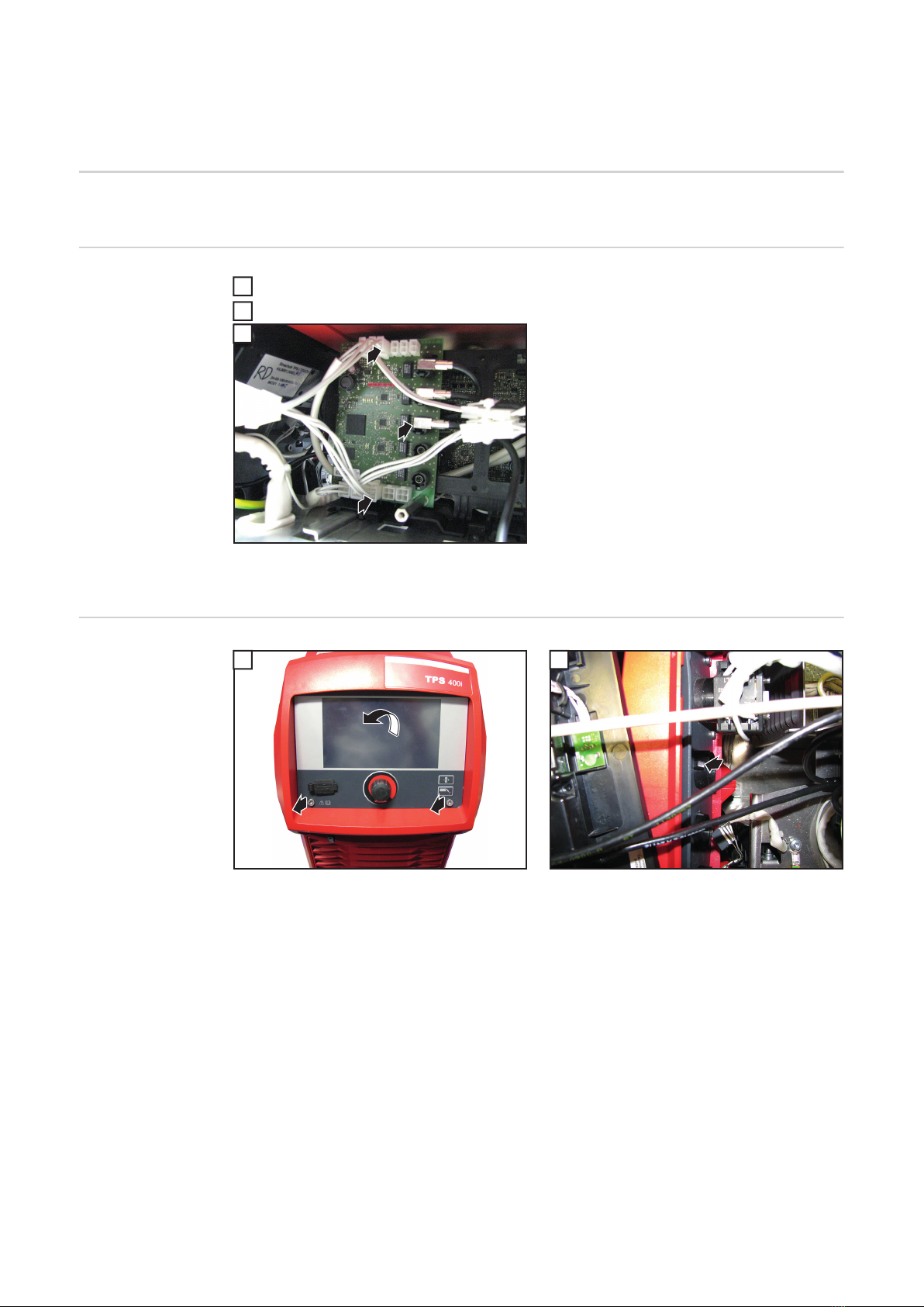
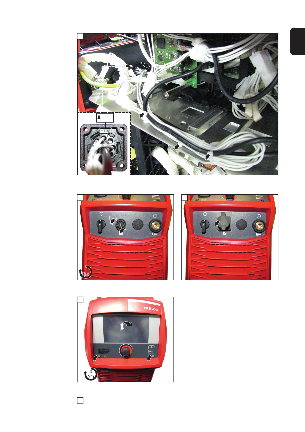
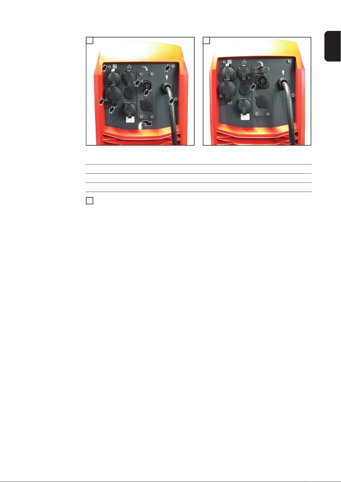
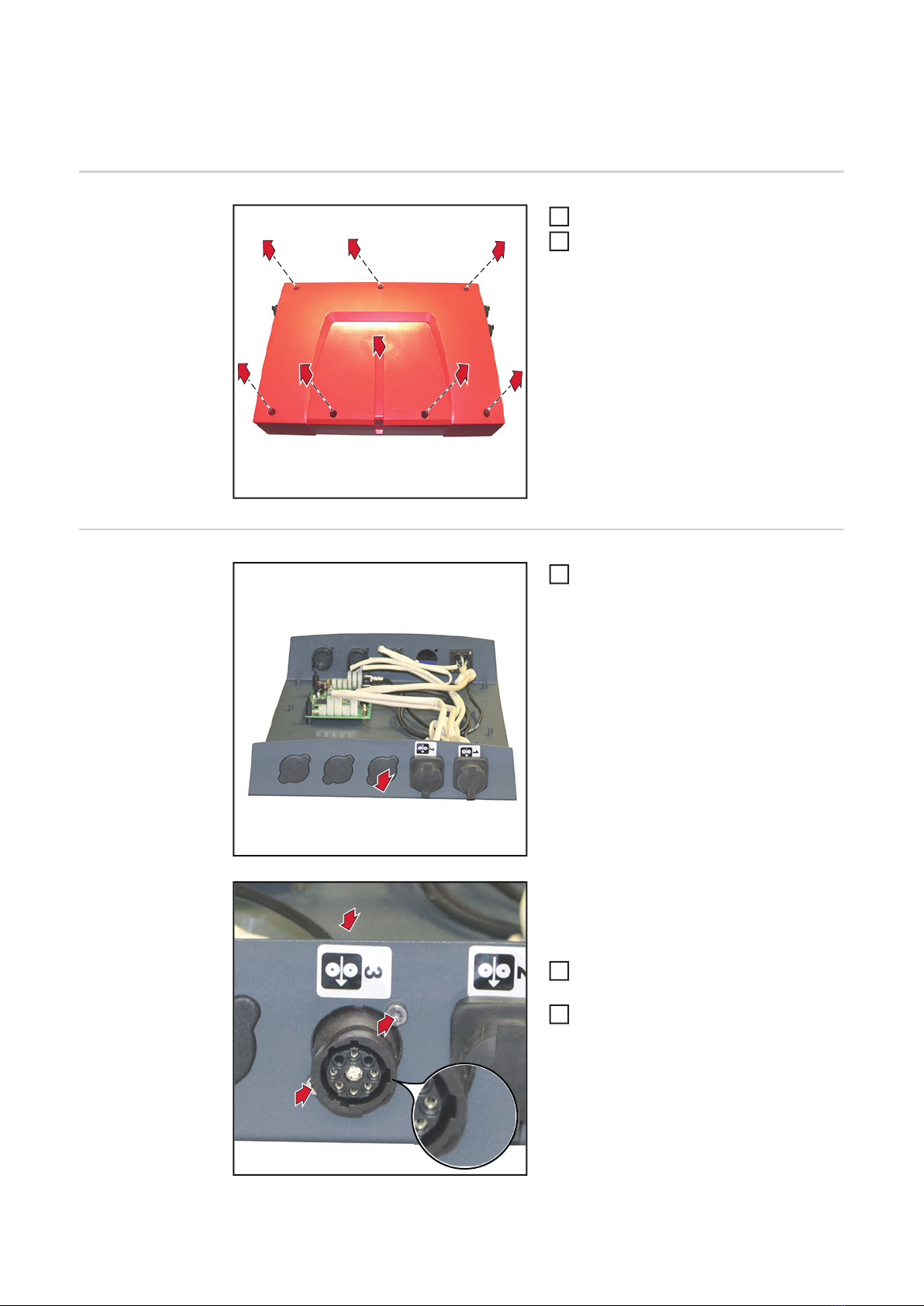
Lieferumfang
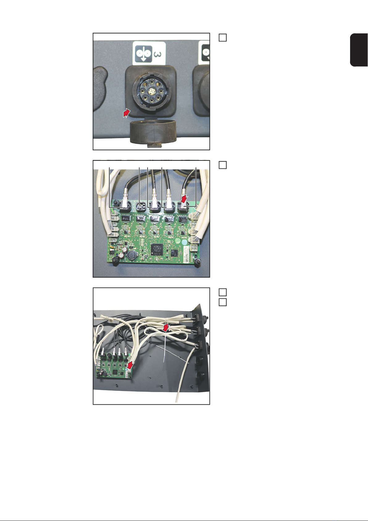
OPT/i TPS SpeedNetConnector
(1) Kabelbaum
(2) Abdeckung
(3) 2 Schrauben 4x12 TX20
(4) 2 Kabelbinder
Ohne Abbildung:
Einbauanleitung
Erforderliches
Werkzeug
- Schraubendreher TX 20
- Schraubendreher TX 25
- Seitenschneider
(2)
(1)
(3)
(4)