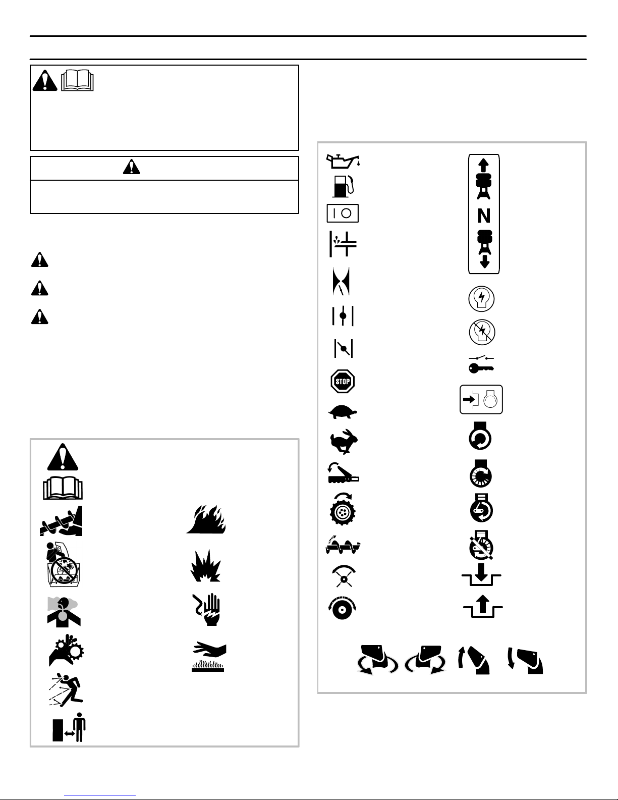
RULES FOR SAFE OPERATION
6
MTF−051059L
IMPORTANT
WARNING: Always disconnect the spark plug wire and place it where it cannot make contact with
spark plug to prevent accidental starting during: Preparation, Maintenance, or Storage of your
snowthrower.
Safe Operation Practices for Snowthrowers
As Recommended By: American National Standards Institute.
Engine Exhaust, some of its constituents, and
certain vehicle components contain or emit
chemicals known to the State of California to
cause cancer and birth defects or other repro-
ductive harm.
Battery posts, terminals and related accesso-
ries contain lead and lead compounds, chemi-
cals known to the State of California to cause
cancer and birth defects or other reproductive
harm. WASH HANDS AFTER HANDLING.
IMPORTANT: Safety standards require operator presence
controls to minimize the risk of injury. Your snowthrower is
equipped with such controls. Do not attempt to defeat the
function of the operator presence control under any cir-
cumstances.
Training
1. Read the operating and service instruction manual care-
fully. Be thoroughly familiar with the controls and the
proper use of the equipment. Know how to stop the unit
and disengage the controls quickly.
2. Never allow children to operate the equipment. Never
allow adults to operate the equipment without proper
instruction.
3. Keep the area of operation clear of all persons, particu-
larly small children and pets.
4. Exercise caution to avoid slipping or falling especially
when operating in reverse.
Preparation
1. Thoroughly inspect the area where the equipment is to
be used and remove all doormats, sleds, boards, wires,
and other foreign objects.
2. Disengage all clutches before starting the engine
(motor).
3. Do not operate the equipment without wearing adequate
winter outer garments. Wear footwear that will improve
footing on slippery surfaces.
4. Handle fuel with care; it is highly flammable.
a. Use an approved fuel container.
b. Never remove fuel tank cap or add fuel to a running en-
gine (motor) or hot engine (motor).
c. Fill fuel tank outdoors with extreme care. Never fill fuel
tank indoors.
d. Replace fuel cap securely and wipe up spilled fuel.
e. Never store fuel or snowthrower with fuel in the tank
inside of a building where fumes may reach an open
flame or spark.
f. Check fuel supply before each use, allowing space for
expansion as the heat of the engine (motor) and/or sun
can cause fuel to expand.
5. For all units with electric starting motors use electric
starting extension cords certified CSA/UL. Use only with
a receptacle that has been installed in accordance with
local inspection authorities.
6. Adjust the snowthrower height to clear gravel or crushed
rock surface.
7. Never attempt to make any adjustments while the en-
gine (motor) is running (except when specifically recom-
mended by manufacturer).
8. Let engine (motor) and snowthrower adjust to outdoor
temperatures before starting to clear snow.
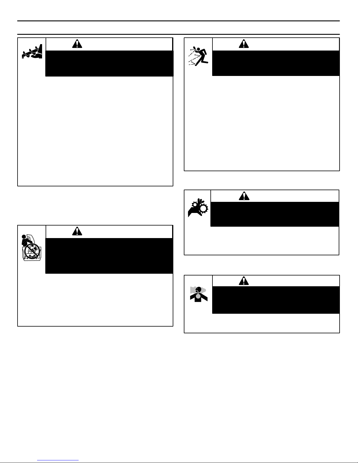
9. Always wear safety glasses or eye shields during oper-
ation or while performing an adjustment or repair to pro-
tect eyes from foreign objects that may be thrown from
the snowthrower.
Operation
1. Do not operate this machine if you are taking drugs or
other medication which can cause drowsiness or affect
your ability to operate this machine.
2. Do not use this machine if you are mentally or physically
unable to operate this machine safely.
3. Do not put hands or feet near or under rotating parts.
Keep clear of the discharge opening at all times.
4. Exercise extreme caution when operating on or crossing
gravel drives, walks or roads. Stay alert for hidden haz-
ards or traffic.
5. After striking a foreign object, stop the engine (motor),
remove the wire from the spark plug, thoroughly inspect
snowthrower for any damage, and repair the damage
before restarting and operating the snowthrower.
6. If the unit should start to vibrate abnormally, stop the
engine (motor) and check immediately for the cause.
Vibration is generally a warning of trouble.