Fruitland FB User manual

I
FB Blowers

MANUFACTURER DECLARATION
MOD................................................................................................................................................
SERIAL NUMBER........................................................................................................
YEAR...............................................................................................................................................
The pump should not be operated until verification can be provided that the installation conforms to directive
2006/42/CE and any current revisions. Always be sure that the installation of the pump conforms to all
applicable installation and operational requirements pertaining to the country and region for which its use is
intended.
PUMP FEATURES
VACUUM PERFORMANCES
MOD. Q* RPM 20%-6”Hg 50%-15”Hg 80%-24”Hg 90%-27”Hg
m3/h-cfm m3/h-cfm Kw m3/h-cfm Kw m3/h-cfm Kw m3/h-cfm Kw
FK1600 1600-950 2000 790-465 7 688-405 14 323-190 21
2500 986-580 9 860-505 18 400-235 26 BO*
3000 1215-715 11 1096-645 23 655-385 31 43-25 35
3500 1428-840 12 1292-760 25 888-522 37 187-110 41
FK2000 2300-1350 2000 1215-715 10 1020-600 20 357-210 32
2500 1547-910 12 1351-795 25 646-380 39
3000 1887-1110 14 1683-990 29 952-560 46 BO*
3300 2084-1226 16 1904-1120 34 1194-702 53 145-85 59
Q = Generated capacity / BO = Blanked Off

DIMENSIONS AND WEIGHT
MOD. A B C D E F G H I J L M N O K
mm in. mm in. mm in. mm in. mm in. mm in. mm in. mm in. mm in. mm in. mm in. mm in. mm in. mm in. mm in.
FK1600 652 25,7 268 10,55 384 15,1 433 17 157 6,2 50 2 100 4 12 0,47 310 12,2 45 1,77 155 6,1 155 6,1 M16 / 125 5 318 12,5
FK2000 752 29,6 318 12,52 434 17,1 433 17 157 6,2 100 4 200 8 12 0,47 310 12,2 45 1,77 155 6,1 155 6,1 M20 / 155 5 318 12,5
P Q R S T U V Z W X Y r d Z WEIGHT
mm in. mm in. N° mm in. mm in. mm in. mm in. mm in. mm in. mm in. mm in. mm in. mm in. mm in. Kg lbs
FK1600 380 14,96 420 16,54 8 18 0,71 84 3,3 385 15,16 420 16,54 42 1,65 67,5 2,66 162,5 6,4 7,5 0,3 210 8,27 M12 / 42 1,65
FK2000 380 14,96 420 16,54 8 18 0,71 84 3,3 385 15,16 420 16,54 42 1,65 67,5 2,66 162,5 6,4 7,5 0,3 240 9,45 M12 / 42 1,65

B
¢N
B
-
A
C
T
4 HOLES
¢s
C
- j·
G ¢S
---
0
w
L M
-----
u

WORKING PRINCIPLE
This is a three lobe positive displacement pump and can work as an exhauster and a blower. The gas enters
the pump through the suction port at a certain pressure and temperature. It goes out through the exhaust
port at another pressure and temperature. The pump also features ballast cooling through two auxilary ports.
CONSTRUCTION
The pump includes a housing, two lobe rotors, two covers and two sumps. In the front sump there are two
gears that are fixed at the factory for exact timing of the rotors. In the covers there are two opposing seals,,
a roller and a double ball bearing. Each sump contains gear oil.
In the front sump there is also a roll bearing and seal for the drive shaft. (See spare parts list).

GENERAL INFORMATION
This manual is an integral part of the pump. Strictly follow all information and guidlines before
assem-bly and integration to any vacuum system. FRUITLAND will not be responsible for damages
or injuries resulting from improper operation of this equipment. Owners, operators and installers
must adhere to all instructions provided in this manual. FRUITLAND will not be responsable for
damages due to the use of spare parts which are not original parts supplied by or approved by
FRUITLAND.
STORAGE AND HANDLING
When unpacking FRUITLAND products, always check that all parts are shipped in accordance with the
packing slip and other shipping documentation and that the products have not been damaged in shipment.
FRUITLAND products are carefully packaged for shipping. The ports are temporarily sealed to prevent
contamination from entering the pump and the drive shaft is protected from rusting during shipment.
For handling the pump, proceed as follows:

Storage:
Keep the pump in a protected place and at the following climatic conditions:
- Temperature from: -20 °C to 40 °C
- Relative humidity from: 10% to 80%
- For higher humidity use an anti-rust oil on exposed parts
Warning
Use anti-rust oil with fire point over 200 °C
Warning
Dispose the used anti-rust oil in accordance with local regulations.
INSTALLATION
Warning
THE PUMP IS DELIVERED WITHOUT OIL. OIL MUST BE ADDED TO THE PUMP PRIOR TO OPERA-
TION. USE SYNTHETIC EP 220 OIL.
QUALIFIED PERSONNEL
Only qualified and trained personnel who are familiar with the FRUITLAND products should work on, repair
or operate the pump. Original parts supplied by or approved by FRUITLAND must only be used for repair and
main-tenance. Failure to comply with the instructions provided in this manual, may lead to the following
dangers:
- Increased temperature rise beyond the safe operating temperature of the pump and as a burning hazard.
- Danger due to the shaft rotation and other mechanically moving parts.
- Noise generated beyond acceptable limits - hearing protection must be worn in close proximity to the pump.
- This pump is suitable only for applications as described in this manual. Other applications must be approved
by the factory.
If the pump is placed on an irregular base, before tightening it to the frame, check that all four feet touch the
base properly and, if need, use appropiate shims.
The drivetrain coupling or belts must be installted as prescribed by their respective manufacturers.
Under no circumstances must liquids, dust or any kind of solid matter enter the pump. If this happens it will
likely cause catastrophic failure of the pump. It is necessary to protect the pump with appropriate safety
valves and filters. The pump must be used for the purpose for which it was designed. Any other uses must
be approved by the factory.
Don not use this pump to handle flammable gas or liquids. Contact FRUITLAND for special
applications. Never remove safety guards or filters. Check all guards and filters every time prior to operating
the pump.

PIPING TO AND FROM THE PUMP
Using a thick walled pipe reduces the ambient noise effect. Clean the inside of the pipes prior to installation
to prevent foreign debris from getting inside the pump and causing damage. Don’t create short radius curves.
Pipes should be seperately supported, not by the pump. The pump should be isolated from the pipes by
means of flexible connections fitted between the silencers, suction filter and the ports.
PRESSURE RELEIF VALVE
Usually the valve is supplied unadjusted.
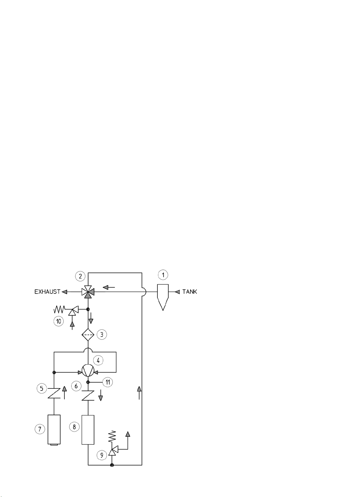
ASSEMBLING LAYOUT
1 Secondary shut-off valve
2 4 way valve
3 Suction filter
4 Pump
5 Check valve
6 Check valve
7 Silencer
8 Silencer
9 Vacuum control valve
10 Pressure reliefe valve
11 Temperature thermocouple
VACUUM MODE

PRESSURE MODE
Set the adjustment starting for the lower preload and increase it by tightening the regulation nuts up to the
desired pressure.
COUPLING ALIGNMENT
Correct alignment of the pump coupling is absolutely necessary.
- Measure the alignment with proper instrumentation
- Keep the correct distance between the two coupling faces (see supplier instructions)

V-BELT DRIVE TENSIONING
h (mm) = t/100 x 1,5
INSTRUCTIONS FOR TRUCK INSTALLATION OF
FBVACUUM PUMPS
BASE FRAME
Please follow these instructions when you install the pump on a truck chassis:
First mode
The pump has to be installed on a steel frame with machined base to ensure the flatness with the pump base.
The frame has to be strong enough to avoid deformations due to the chassis elastic strain. The frame has to
be fixed on the chassis with a correct number of shock mounts. The pump and the cooling air manifold have
to be fixed on the frame without any vibration pad. The pump can be installed and supported using either the
discharge and sucking flanges or the proper feet. If the feet are used, before tightening to the frame, check
that all four feet touch the base properly (< 0,2 mm) and, if needed, use appropriate shims on the fourth
foot.
Warning: If the pump is placed on an irregular base, malfunctioning may be occur. During tightening opera-
tion check the free manual rotation of the shaft. Use just one bolt per foot.
Second mode
The pump with the manifold has to be installed on a steel frame machined with the flattest base possible and
with four shock mounts. The frame could be fixed directly to the chassis.
All the above indications are very important to avoid damage to the pump while it is running.
Warning: The pump failure may not occur immediately at start-up but at working temperature.

COOLING AIR INJECTION MANIFOLD
The pump is supplied with a manifold that connects the lateral ports for cooling air flow.
The manifold is very important for a safe operating temperature. When you connect the silencer, be sure that
no area reductions or pipe steps are used.
A flexible coupling has to be used between the manifold and silencer pipe to avoid external forces and trans-
mission vibrations.
The silencer has to be properly fixed to the frame.
The same procedures have to be followed with the exhaust silencer.
PIPING
The connecting pipes, should be as short as possible and with the same diameter as the pump flange, with
corrected curves in order to prevent pressure losses and overheating temperatures.
A flexible coupling must be used between the suction and discharge pump ports and the pipes to avoid trans-
mission forces against the pump.
SILENCERS
Silencers are recommended to reduce the noise level in these types of pumps.
The noise is related to the capacity, frequency and speed of the pump; for this reason check the pump data
before sizing the silencers.
Pay attention to the silencer pressure losses which should not be higher than 100 mm of water (4”) column.
The inlet of the air injection cooling silencer should be orientated away from the truck motor and pump ex-
haust.
The two silencers have to be fixed to the frame with proper brackets and connected to the pipes with elastic
couplings, to avoid transmission forces against the pump.
FILTRATION
The suction air coming from the tank has to be properly filtered (10 μmm) before entering the pump. If a filter
is used in the air injection cooling silencer, regular cleaning must be performed since it may get clogged re-
sulting in pump overheating ( use clogged filter gauge ).
Different filtration systems are used depending on the material being moved. Be sure to contact FRUITLAND
for the correct filter application.
When handling liquids, a primary shut-off valve, separator cyclone and final filter are needed. When handling
powdered materials a bag filter must be used.
INSTRUMENTATION
The pump is designed to operate continuously at maximum vacuum with the inlet cooling air temperature of
37 °C (100 °F).
If the inlet air temperature is higher than the above data, it can cause overheating of the pump and discharge air.
We recommend the installation of a temperature thermocouple mounted close to the pump discharge port,
set to operate at 140 °C (285 °F). The thermocouple will activate an alarm and open the vacuum relief valve.
PRESSURE RELIEF VALVE
This valve is necessary when the system is operating in pressure mode.
The valve has to be set to the maximum discharge pressure, according to the data sheet and sized for nomi-
nal air flow plus 50% of the discharge pressure.

DRIVES
The pump is designed to be suitable for all types of drives.. The pump speed should not exceed 3.400 RPM.
Couplings and shafts must be perfectly aligned.
Always use the proper tools and equipment to install the coupling or sheaves so as not to damage them.
Use the correct V-belts designed for the application.
When using a hydraulic motor, make sure that it is designed properly for the application.
When using a sliding universal joint make sure that the inclination angle doesn’t exceed 5 degrees.
Consult pump data for the correct shaft, coupling, hydraulic motor and universal joint drive.
MAINTENANCE
Daily: Check the oil level in the front and back side.
Check the inlet filter, clean and replace the strainer if necessary.
Check and drain the cyclone filter.
If required: In case the oil sights are dirty, clean them, or replace if damaged.
If foreign materials or liquid gets into the pump, it will cause severe damage which will void the
warranty.
Pump operating: Regularly check the air discharge temperature as it directly relates to the air injection cooling
temperature, vacuum and efficiency of the pump.
If the air temperature exceeds 140 °C (285 °F), stop the pump and check the following:
- The pump RPM must not operate below 800.
- The silencers should be checked and cleaned.
- The pressure loss from the suction to the discharge has to be less than 125 mm (5”) of
water column.
- Make sure that the engine truck and pump exhausts are not in close proximity to the cooling
air inlet.
- The outside air temperature is not above 37 °C (100 °F).
If the pump doesn’t produce vacuum:
- Check the gauge connections and fittings.
- Check all the pipe gaskets and connections between the pump and the tank.
- Check all the filter, valves and tank seals.
- Check the internal pump lobes for damage and ensure that clearances are acceptable.

STARTING
ROTATION AND AIRFLOW DIRECTION
The rotation is usually CCR (counter clock-wise rotation) and the flow is as shown below
For CR (clock-wise rotation) please specify upon placing an order.
Warning!
Do not install the pump inclined because this will change the correct oil level in the sumps.

STARTING
Check the transmission alignment and belt tension
Check that the pump shaft rotates by hand and in the correct direction
Check that the pump is secure and installed correctly
Check that the inside of the pipes have been well cleaned
Check that all the pipe connections have been tightened and sealed
Check the relief valve set up
Open all the pipe valves
Increase the RPM gradually up to the rated value
Increase the pressure gradually closing the valves
After a few hours, check for oil leaks, strange noises and vibrations
Warning !
Hearing protection must be worn by all personnel when in close proximity to pump operation
Warning!
The pump surfaces, accessories and pipes will became hot during operation and may cause burning if com-
ing in contact with skin
LUBRICATION
The pump life depends on the quality and correct lubrication. Check the oil level on the sumps trough the
sight glasses and , if necessary, add the necessary quantity. Use a synthetic EP 220 oil. We prescribe:
ESSO SPARTAN SYNTETIC EP 220 or similar
When the ambient temperature is below 10 °C, run the pump for a few minuts with no pressure or vacuum.
This will allow the oil in the sumps to warm up.
The first oil change should be done after 200 operating hours, afterwhich time the oil must be changed
every 4.000 hours. Check the oil in both sumps trough the sight glasses and if necessary, add oil to the cor-
rect amount.
Quantity:
Front side sump:
Back side sump:

Before the pump is stopped, run it for a few minutes without pressure or vacuum inside and with valves
opened; in this way no humidity condensation will remain inside. With cold temperature this condensation
could create ice and problems when the pump is re-started. a small valve (3/8”) may be added to the bottom
of the pump to discharge possible condensation.
TROUBLE SHOOTING
The most common causes of faulty operation are due to clogged inlet filter, broken instrumentation, excess
oil, wrong RPM and operating under excess pressure.
A clogged inlet filter or cooling silencer can lead to a restriction of vacuum capacity, or pressure and cause
overheating. This could result in pump damage.
During initial operation, check the filter frequently and clean if necessary.

PROBLEM CAUSES SOLUTIONS
High discharge
pressure
Pipes diameter to small Change the pipes
Air capacity to high Reduce the RPM
Discharge pipe obstructed Remove the obstruction
No air flow Speed to low Check speed with data sheet
Wrong rotation Change rotation if wrong
Pipe obstruction Check piping, valves, silencers for
obstruction
Low capacity Speed to low Check drive selection or belt
slippage
Excessive pressure rise Check vacuum and discharge
pressure
Pipe obstruction Check piping, valves,
silencers for obstructions
Inside clearances Check the inside clearances for
erosion
Exccesive pump
temperature
Excessive differential pressure Reduce differential pressure
Worn impellers clearances Restore clearances
To low operating RPM Increase pump speed
Clogged filter, valves,silencers Remove cause
Oil level to high Reduce the oil level
Vibrations Impellers rubbing Chech if there is damage, repair and
start again. If necessary readjust
clearance between impellers
Worn bearings or gears Replace them
Misalignment Re-adjust
Oil loss Level to high Re-adjust the level
Worn seals Replace
Sump vents plugged gaskets Clean vents and replace

MAINTENANCE
WARNING!
Prior to beginning pump maintenance, be sure that the pump is not running, the surfaces are cold and the
atmospheric pressure is restored inside and in the pipes.
Check that any method of powering the pump is off and in no danger of being activated.
WARNING!
Dispose of used oil in accordance with local environmental rules and regulations
- In case of oil leakages it may be necessary to change the drain plugs or the seals.
- Clean daily or replace the inlet filter. If the filter is clogged the pump capacity is reduced and may cause a
high temperature condition, or damage to the pump from foreign material. If the pump fails as a result of this
situation it will not be covered by warranty.
- If liquid is ingested into the pump, remove the inlet filter, clean the compression chamber with a solvent not
harmful to the cast iron or with a small quantity of diesel fuel. There is the possibility that the overflow liquid
will be also in the discharge and cooling silencers, so it is also necessary to drain, clean and dry them.
- Chek the discharge temperature regularly with a gauge. In any case this temperature has to be higher than
140 °C (285 °F). If this happens, stop the pump immediatly and check:
- RPM
- Pressure on the system
- Envinronment temperature ( below 37 °C - 11 °F)
Excessive power Speed to high Check speed with rating
Pressure to high Check inlet vacuum and
discharge pressure with rating
Impellers rubbing Check if there is contact
Knocking Out of time Check timing
Excessive differential pressure Reduce pressure. Check relief valve
To high discharge temp Re-set if necessary
Worn gears Replace and reset timing
Worn bearings Replace and reset timing

- Inlet and discharge silencers which may need to be unclogged, that the pressure loss is under 300 mm
(12”) of water.
- Truck engine exhaust is not discharging into the air injection silencer
- Discharge pump silencer doesn’t dischage into the air injection silencer
If the pump doesn’t produce vacuum check:
- RPM
- Gauges and connections
- Pipes leakages
- Tank leakages
- Filter leakages
- Pump wear
ACCESSORIES
Manifold
Primary shot-off valve
Secondary shot-off valve (Cyclone)
Bag filter
4 way valve
Suction filter
Silencers
Check valve
Pressure reliefe valve
Warning
FRUITLAND will not be liable for damages or injuries caused by the use of non original spare parts and
accessories.
FRUITLAND will not be liable for damages or injuries caused by failure to comply with the instructions
given in this manual.

SPARE PARTS

PARTS LIST
ITEM CODE PART DESCRIPTION QTY NOTES
1 CPO.30017 HOUSING 1
2 ROT.30021 DRIVE ROTOR 1
3 ROT.30022 DRIVEN ROTOR 1
4 ING.21010 GEAR 2
5 CTR.30005 FRONT COVER 1
6 FLN.30035 FRONT HEAD PLATE 1
7 BLA.20023 WEAR BUSH 1
8 FLN.30036 REAR HEAD PLATE 1
9 FLN.20039 RETAINER FLANGE 2
10 CTO.50014 BEARING 2
11 CTR.30006 REAR COVER 1
12 CTO.50013 BEARING 1
13 ATN.80010 SEAL RING 1
14 CTO.50011 BEARING 1
15 CTO.50012 BEARING 1
16 SPS.21000 SHIM 2
17 FSB.70001 LOCKING BUSH 4
18 CHI.70006 FLAT KAY 1
19 AOR.80009 O RING 4
20 AOR.80011 O RONG 1
21 IDL.22002 LEVEL GAUGE 2
22 TPO.70007 PLUG 4
23 TPO.70005 PLUG 2
24 RDA.70015 WASHER 20
25 VTE.70030 SCREW 20
26 ASI.70001 CIRCLIP 1
27 ASI.70000 CIRCLIP 2
28 SPN-70005 PIN 4
29 VTE.70034 SCREW 2
30 VTE.70039 SCREW 1
31 VTE.70016 SCREW 1
32 BLA.20026 SPACER 2
33 DDO.70012 RING NUT 2
34 BLA.20027 SPACER 2
35 DDO.70013 RING NUT 2
36 TPO.70009 VENT PLUG 4
37 RDS.70000 TAB WASHER 1
38 VTE.70038 SCREW 8
39 CFA.22002 SHAFT COVER 1
40 FLN.20042 IMPELLER 1
41 BLA.20028 WEAR BUSH 4
42 ATN.80013 SEAL RING 4
43 BLA.20029 SPACER 4
44 AOR.80012 O.RING 4
45 ATN.80014 LIPSEAL 4
46 BLA.20030 SPACER 1
47 TPO.70011 PLUG 2
48 CFA.22002 SHAFT COVER 1
Table of contents
Popular Blower manuals by other brands

Craftsman
Craftsman 358.794762 Operator's manual

Black & Decker
Black & Decker LSW20 instruction manual

SNOWJOE
SNOWJOE SUNJOE SJ-24V-X2-BVM143-CT Operator's manual

Gardner Denver
Gardner Denver DuroFlow 45 Series PARTS LIST OPERATING AND SERVICE MANUAL

EDM Product
EDM Product 08787 instruction manual

F.F. Group
F.F. Group BBL 870/40V PLUS Original instructions

Elektror
Elektror A-HP Operating and assembly instructions

fybots
fybots Sweep XL user manual

GGP ITALY SPA
GGP ITALY SPA Blower Operator's manual

BorMann
BorMann BPB6500 instruction manual

Xylem
Xylem JABSCO Flexmount 36740-Series Installation and operation manual

Simco
Simco minion2 Operation & maintenance instructions