iv
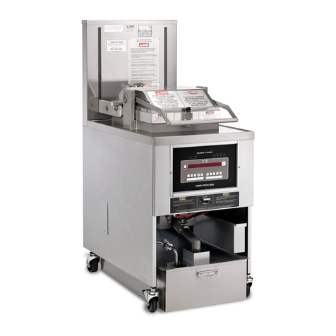
BIELA14 SERIES GEN II LOV™ ELECTRIC FRYERS
TABLE OF CONTENTS
CAUTIONARY STATEMENTS........................................................................................................................................i
WARRANTY STATEMENT ............................................................................................................................................ii
ELECTRICAL POWER SPECIFICATIONS............................................................................................................... iii
CHAPTER 1: Service Procedures
1.1 General...........................................................................................................................................................1-1
1.2 Replacing a Computer....................................................................................................................................1-1
1.3 Replacing Component Box Components.......................................................................................................1-1
1.4 Replacing a High-Limit Thermostat ..............................................................................................................1-3
1.5 Replacing a Temperature Probe.....................................................................................................................1-3
1.6 Replacing a Heating Element.........................................................................................................................1-5
1.7 Replacing Contactor Box Components..........................................................................................................1-7
1.8 Replacing a Frypot.........................................................................................................................................1-8
1.9 Built-In Filtration System Service Procedures.............................................................................................1-10
1.9.1 Filtration System Problem Resolution........................................................................................1-10
1.9.2 Replacing the Filter Motor, Filter Pump and Related Components ...........................................1-11
1.9.3 Replacing the Filter Transformer or Filter Relay.......................................................................1-13
1.10 ATO (Automatic Top-Off) Service Procedures...........................................................................................1-13
1.10.1 ATO Troubleshooting................................................................................................................1-14
1.10.2 ATO Board Pin Positions and Harnesses...................................................................................1-15
1.10.3 Replacing the ATO board, LON Gateway, ATO pump relay or Transformer...........................1-16
1.10.4 Replacing the ATO Pump ..........................................................................................................1-16
1.11 MIB (Manual Interface Board) Service Procedures.....................................................................................1-16
1.11.1 Manually Draining, Refilling or Filtering with the MIB Board.................................................1-17
1.11.2 MIB Troubleshooting.................................................................................................................1-18
1.11.3 MIB Pin Positions and Harnesses ..............................................................................................1-20
1.11.4 MIB Display Diagnostics...........................................................................................................1-21
1.11.5 MIB Display Characters.............................................................................................................1-22
1.11.6 Replacing the MIB board...........................................................................................................1-22
1.11.7 Control Power Reset Switch.......................................................................................................1-22
1.12 RTI Service Issues .......................................................................................................................................1-23
1.12.1 RTI MIB Tests ...........................................................................................................................1-23
1.12.2 RTI LOV Wiring........................................................................................................................1-24
1.12.3 RTI Plumbing Schematic ...........................................................................................................1-24
1.12.4 RTI LOV Quick Reference........................................................................................................1-25
1.13 AIF (Automatic Intermittent Filtration) Service Procedures........................................................................1-27
1.13.1 AIF Troubleshooting..................................................................................................................1-27
1.13.2 AIF Actuator Board Pin Positions and Harnesses......................................................................1-28
1.13.3 Replacing an AIF Board.............................................................................................................1-29
1.13.4 Replacing an Actuator................................................................................................................1-29
1.14 M3000 Computer Service Procedures..........................................................................................................1-30
1.14.1 M3000 Computer Troubleshooting............................................................................................1-30
1.14.2 M3000 Useful Codes and Passwords.........................................................................................1-33
1.14.3 Service Required Errors.............................................................................................................1-34
1.14.4 Error Log Codes.........................................................................................................................1-35
1.14.5 Tech Mode .................................................................................................................................1-36
1.14.6 M3000 Filter Error Flowchart....................................................................................................1-37
1.14.7 M3000 Menu Summary Tree.....................................................................................................1-38
1.14.8 M3000 Board Pin Positions and Harnesses................................................................................1-39
1.15 Loading and Updating Software Procedures................................................................................................1-40
1.16 Data Network Flowchart..............................................................................................................................1-41
1.17 Interface Board Diagnostic Chart.................................................................................................................1-42
1.18 Probe Resistance Chart ................................................................................................................................1-43
1.19 Wiring Diagrams..........................................................................................................................................1-44
1.19.1 Component Wiring Domestic.....................................................................................................1-44
1.19.2 Component Wiring CE...............................................................................................................1-45
