Replace parts in reverse rder. Take care n t t ver
tighten gland nut t av id p ssibility f cracking
ceramic material. The spark gap is pre-determined
and cann t be adjusted. D n t attempt t alter gap
by bending electr de.
3.7 HIGH TEMPERATURE LIMIT DEVICE
This is an electrical therm stat which interrupts
therm c uple circuit. In event f failure f c ntr l
therm stat (emb died in gas c ntr l valve), the high
temperature limit device will sense excessive il
temperature and pen - thus all wing gas valve in
c ntr l t cl se.
Once triggered, high temperature limit device must be
manually re-set by pressing red butt n n
therm stat b dy.
To Remove
a) Drain pan.
b) Rem ve fr nt facia panel by rem ving fixings in
panel underside.
c) Pull ff electrical c nnecti ns fr m interrupter
situated at gas c ntr l valve rear and release
electrical leads.
d) Und f ur fixings and rem ve c ntr l chamber
base panel.
e) Und gland nut sealing capillary tube where it
enters pan.
Note
THE SAFETY PHIAL IS THE UPPER PHIAL
f) Fr m inside pan, release therm stat phial fr m
m unting bracket by m ving it slightly t ward rear
f pan and then upward.
g) Ease phial and capillary tube thr ugh pan fitting.
h) Rem ve tw fixings that secure therm stat t
bracket and rem ve c mplete unit fr m fryer.
Replace in reverse rder, taking care n t t damage
capillary tube. Thereafter -
j) Press red butt n t ensure c ntacts are cl sed
bef re lighting fryer.
k) Fill pan with il t level mark.
m) Check sealing gland d es n t leak but d n t
vertighten gland nut.
n) Heat pan at maximum temperature setting and
all w c ntr l therm stat t cycle nce r twice t
ensure that high temperature limit device d es n t
trigger prematurely.
Operati n f safety therm stat must be checked at
regular intervals. In rder t raise il temperature
sufficiently t enable safety therm stat t perate,
it will be necessary t rem ve sens r bulb f c ntr l
therm stat fr m il. This c nditi n can be
acc mplished by the f ll wing pr cedure:
a) Drain pan.
b) Rem ve upper panel ab ve d r by rem ving
fixings in panel underside.
c) Und fixings and rem ve c ntr ls chamber base
panel.
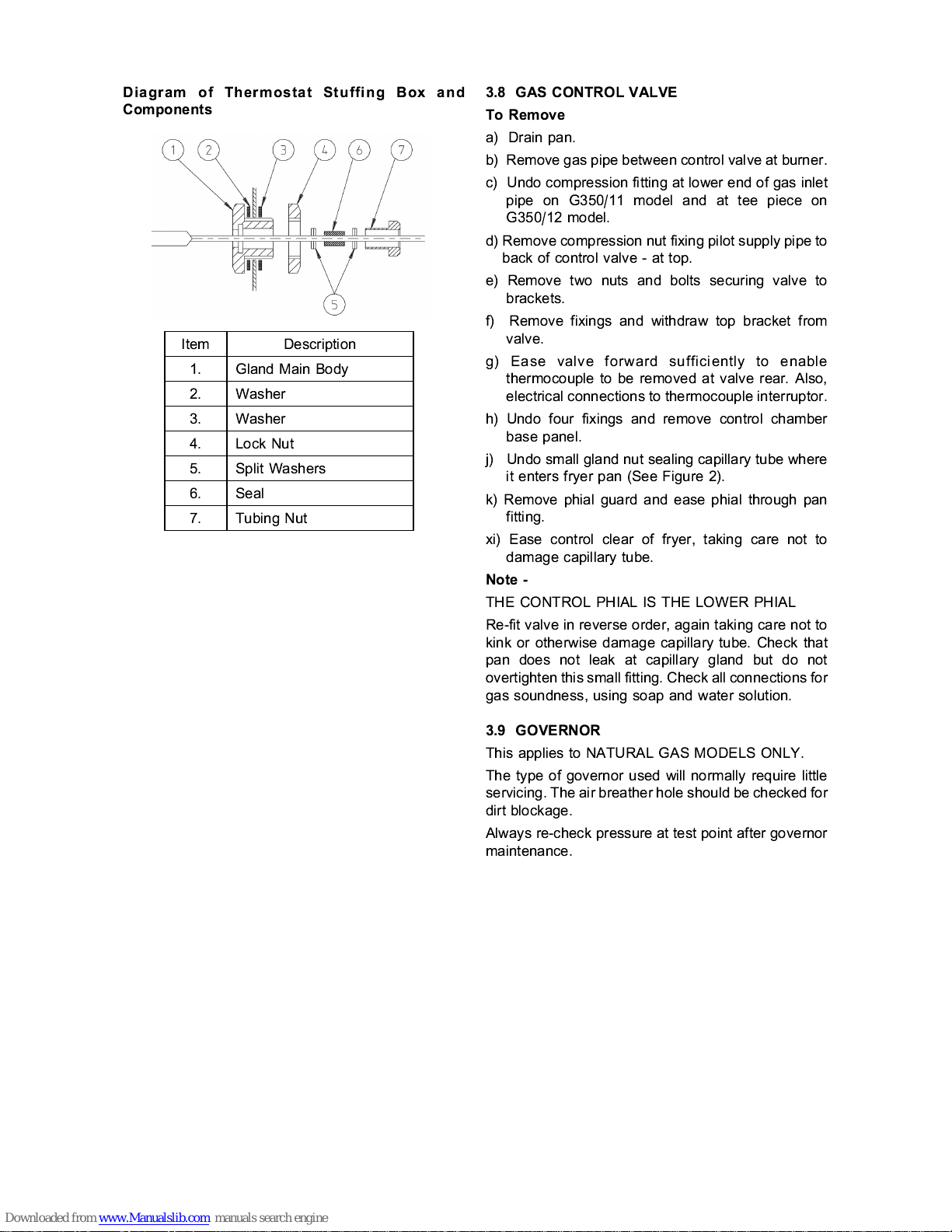
d) Slacken small gland nut sealing capillary tube
where it enters fryer pan (See Figure 2).
Note
THE CONTROL PHIAL IS THE LOWER PHIAL
e) Rem ve phial guard and ease c ntr l therm stat
sens r t wards pan rear t clear l cating brackets.
Draw capillary tube thr ugh glands t enable
sens r t be suspended ut f the il when pan is
t be re-filled t marked level.
f) Tighten small gland nut t temp rarily c mpress
seal n t capillary tube.
g) Temp rarily refit phial guard ver high limit device
sens r.
h) Refill pan with il t marked level.
j) Install a means f measuring il temperature.
A therm c uple-type instrument is preferable but
a mercury therm meter capable f measuring up
t 300
C can be used. The measuring sens r,
i.e. therm c uple r therm meter bulb must be
suspended 25mm bel w il surface in pan centre.
k) Light fryer and carefully bserve rising il
temperature. The safety therm stat, if functi ning
pr perly, will shut- ff gas when il temperature is
between 218
C and 224
C (maximum).
m) If safety therm stat fails t perate at maximum f
224
C, shut ff fryer immediately by pressing " ff"
butt n n gas c ntr l valve (see Secti n 2.5,
Figure 1). All w il t c l bef re investigating
fault.
n) All safety therm stats are accurately calibrated
and checked n new appliances during
manufacture. It is unlikely that calibrati n will need
service adjustment assuming therm stat is n t
therwise faulty.
p) Once satisfied that safety therm stat is functi ning
c rrectly, c ntr l therm stat sens r must be
re-l cated in n rmal p siti n. A reversal f
pr cedures (a) t (h) will achieve this c nditi n.
Note
Replace seal n c ntr l therm stat gland and ensure
that n il leaks are present.