FTE Maximal AV 15N User manual
1 © FTEmaximal
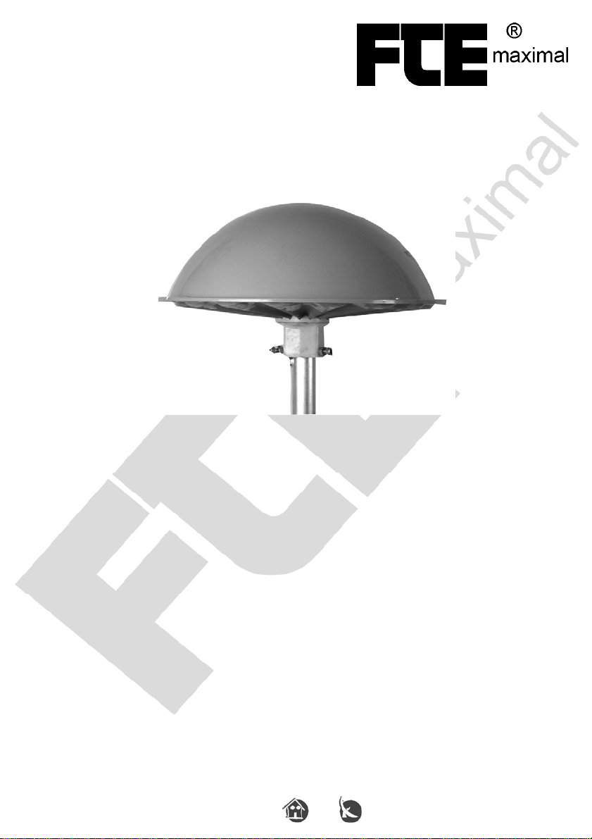
Shipantennas
AV 14N AV 15N AV 16N
The ship antennas AV 14 to 16N are designed to receive radio and TV
transmissions into I, II, II, IV, and V band.
AV 15 and 16N models can also receive signal from the LMK band.
Due to the special design to receive signals from all directions and its stable
construction against the seawater, these antennas are the best solution for ships.
The antenna is full filled with foam and the mounting construction is made with
glass fibre and stainless steel screws.
In order to guarantee a high watertightness, the antenna is connected with a
coaxial cable that can not be changed.
The antenna have an special preamplifier with a low noise factor, that is feeded
by a main amplifier (for example LBS22-12P).
The amplifier allows to supply 2 lines.
There are two operating voltages: 220 / 110 VAC or 24 / 12 VDC.
Manual
for

2 © FTEmaximal
Index
Seite
Safety Instructions
Important notes for your safety
3
Parts included
Is your kit complete?
4
Technical features
Specifications
5
Accessories
What accessories do you need?
6
Mounting
The correct place for mount
Mount the antenna on the top of a mast
7
7
It depends on the combination
Coaxial cable from antenna
Connect the amplifier
9
10

3 © FTEmaximal
Important notes for your safety
Important Notes
The antenna must be installed according to the instructions manual and taking
all necessary cautions.
If these conditions are not followed the manufacturers warranty will be limited or
void.
Please take all necessary safety steps when working with equipment that is
connected to an electric power source.
Please take care of yourself and the people around you.
Is it necessary to read the complete manual?
– Yes, we recommend it.
For your Safety
Caution:
Do not open the housing: you may get an electric shock.
- Equipment must be repaired by a professional.
- No components require to be adjusted inside the antenna.
- When you clean the equipment, first disconnect it from the power source.
Never pull on the cable of the power supply. Try to pull the plug directly,
otherwise the cable will be damaged. Be sure that it is well connected, because
if not it has the potential to start a fire.
A professional must repair defects like this quickly.
Never install this equipment during a storm.
Any TV equipment should be unplugged during a it.
It is possible that a thunderbold can pass through the antenna cable and the
metal parts of the unit and cause an electric shock.
Use the amplifier only in a dry and well-ventilated environment.
The build up of dust inside the unit can cause that it stop to work correctly.
The danger is specially high if any fluids enter into this equipment.

4 © FTEmaximal
Parts included
Is your Kit complete?
Please check your box to ensure that you have all necessary parts:
☺ Antenna
with 20m of coaxial cable
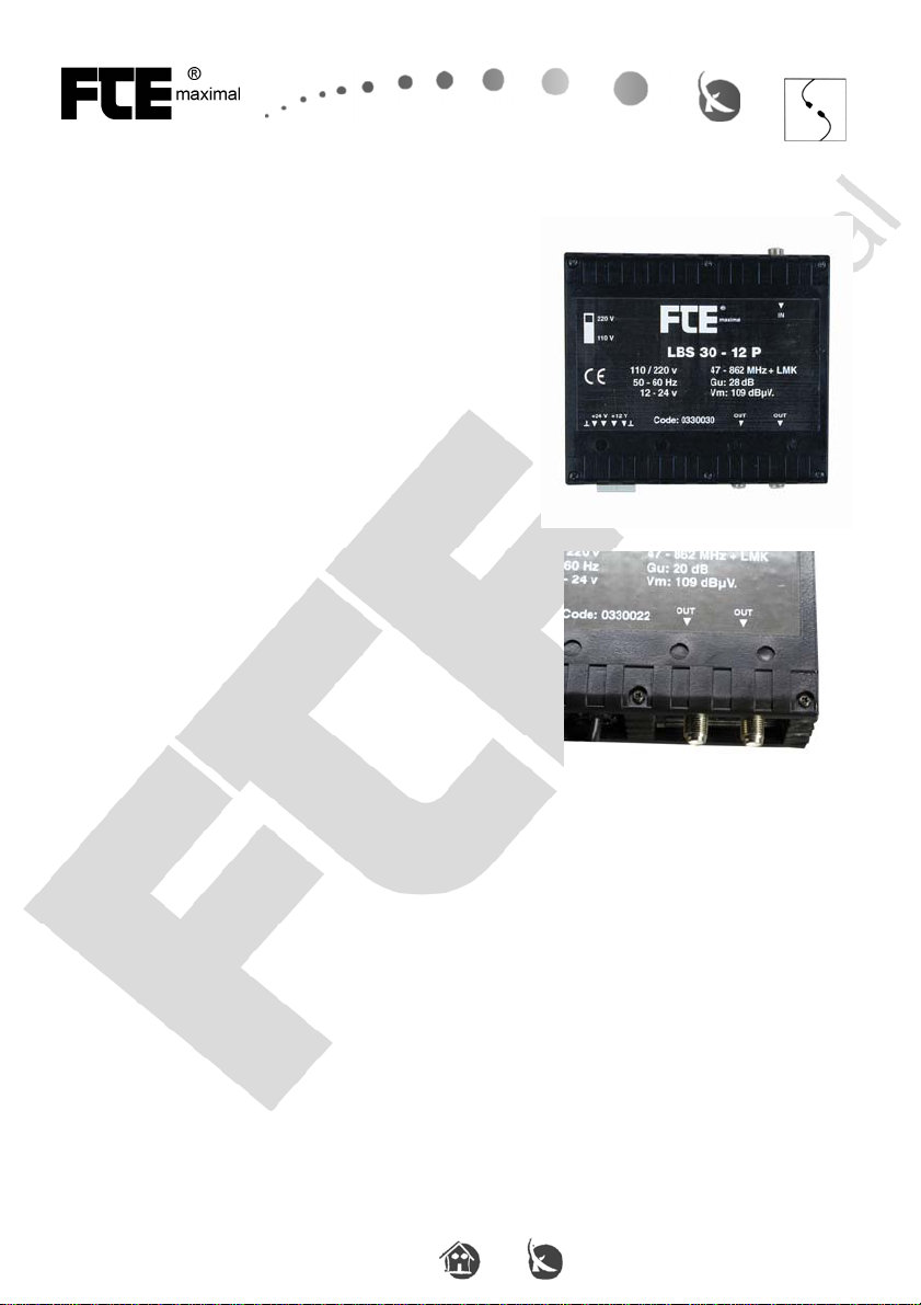
☺ Amplifier:
AV 14N / 15N = LBS 22-12P
☺ Amplifier:
AV 16N = LBS 30-12P
☺ ALLEN key:

5 © FTEmaximal
Technical features
Electrical specifications
AV 14N
Band: BI / FM / BIII / BIV / BV
Gain (dB): 28
Output level (dBµV): 2x10⁹
Noise (dB): 3
Reception angle: 360°
AV 15N
Band: LMK / BI / FM / BIII / BIV / BV
Gain LMK (dB): 18
Gain VHF / UHF (dB): 28
Output level (dBµV): 2x10⁹
Noise (dB): 3
Reception angle: 360°
AV 16N
Band: LMK / BI / FM / BIII / BIV / BV
Gain LMK (dB): 18
Gain VHF / UHF (dB): 28 / 40
Output level (dBµV): 2x10⁹
Noise (dB): 3
Reception angle: 360°
Reception diagram
Mechanical specifications
Total high (mm): 320
High over the mast (mm): 230
Mast for mounting (mm): 38 - 48
Antenna diameter (mm): 540
Wind resistance (N): 98
Weight (kg): 3,5 (without coaxial cable)
Colour: RAL 7001
Material: Teflyte
6 © FTEmaximal
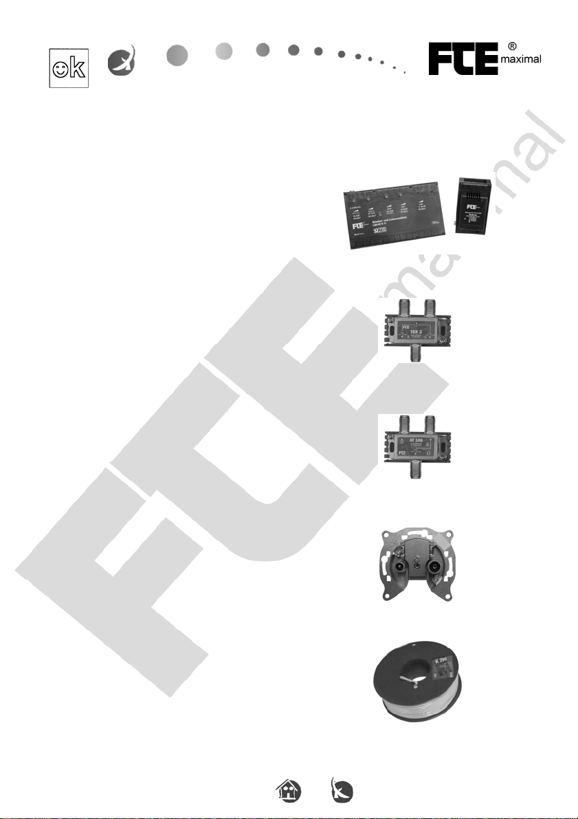
Accessories
What accessories are needed?
To mount an antenna system you may need these accessories:
☺ Line amplifier:
LBA 42R11
☺ Splitter series TER:
2, 3, 4, 6 or 8 outputs
☺ Tab series AT:
1, 2, 4, 6, or 8 outputs
Available attenuations:
8, 10, 12, 15, 20 or 25dB
☺ Outlet series AO:
Available attenuations:
3, 9, 15 or 20dB
☺ Coaxial cable:
K290 Screen > 90dB

7 © FTEmaximal
Mounting
The correct place for mount
The antenna have to be mounted on the top of the mast, because it improves the
signal reception and minimizes reflections from the ship.
To reduce interferences generated by a ship radio, mount the antenna as far as
you can from it.
Mount the antenna on the top of the mast
The antenna must be placed over a vertical mast, with 38 to 48mm of diameter.
The mast will be introduced 100mm into the bottom of the antenna.
The coaxial cable must be placed into the mast. To do it, there must be a hole in
one side of the mast.
The antenna will be fixed to the mast by 3 ALLEN screws separated 120º.

8 © FTEmaximal
Mounting
1. Pass the coaxial cable trough the mast.
2. Place the antenna over the top of the mast.
3. Fix the 3 Allen screws with the included
Allen key.
4. Hold on the screws with a spanner or similar.

9 © FTEmaximal
It depends on the combination
Coaxial cable from antenna
Connect the coaxial cable of the antenna to the amplifier.
The minimum diameter of this cable must be 7mm.
You can not use normal staples to fix the cable to the wall, if they press it.
You can cut the coaxial cable to make it shorter, but remember that it is fixed
inside the antenna.
Important:
Pay attention that there is no part of the net in contact with the inner conductor
cable, because it should produce a short that will not allow a correct signal
transmission through the coaxial cable.

10 © FTEmaximal
It depends on the combination
Connecting the amplifier
CAUTION !
Connect the amplifier to the power source, when you have made all the
connections and selected the correct feeding voltage.
You have 2 possibilities for feeding the amplifier:
1. You can feed the amplifier with the built-in
power supply.
To do it, select with the switch the voltage
you prefer (220 or 110 VAC).
2. Over the DC-block, you can feed the
amplifier with DC current.
You can select 12 or 24 VDC.
11 © FTEmaximal
It depends on the combination
Connecting the amplifier to the antenna
The coaxial cable coming from the antenna will be
connected through the connector IN.
The distribution network will be connected trough
OUT outputs.
Both output are equivalents.
This manual suits for next models
2
Table of contents


