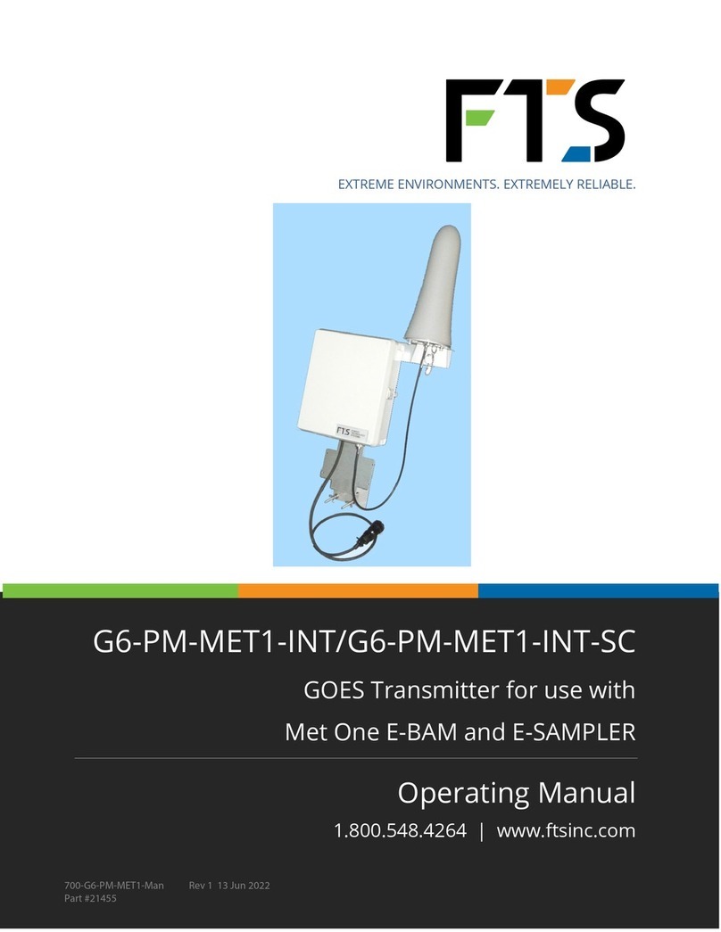
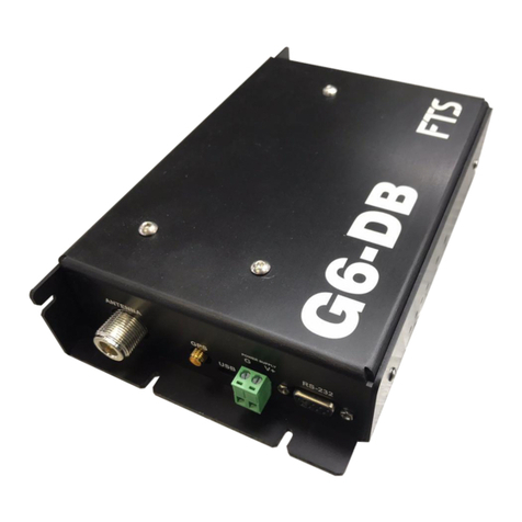
FTS G6 User manual

EXTREME ENVIRONMENTS. EXTREMELY RELIABLE.
G6 GOES/Meteosat Transmitter
Operator’s Manual
1.800.548.4264 | www.ftsinc.com
700-G6-MAN Rev2 11 Jul 2019

i
Contents
1.1 GENERAL................................................................................................................................................................................1
1.2 STATUS PANEL.....................................................................................................................................................................2
1.2.1 Synchronize Clock to GPS Indicator.................................................................................................................2
1.2.2 DATA Indicator.........................................................................................................................................................3
1.2.3 TRANSMIT (TX) Indicator ......................................................................................................................................3
1.2.4 FAULT Indicator .......................................................................................................................................................3
1.2.5 DIAGNOSTIC Button...............................................................................................................................................3
1.3 LED OPERATION..................................................................................................................................................................3
1.4 SATELLITE COMMUNICATION .......................................................................................................................................5
2.1 SITE SELECTION...................................................................................................................................................................6
2.2 POWER....................................................................................................................................................................................6
2.3 ANTENNAS............................................................................................................................................................................6
2.4 MAINTENANCE....................................................................................................................................................................6

Page 1/8
700-G6-MAN Rev. 2 11 Jul 2019
OVERVIEW
1.1 GENERAL
The FTS G6 Transmitter is a device that provides a GOES or Meteosat satellite uplink for use in remote
data acquisition systems. The G6 is certified by the National Environmental Satellite, Data and
Information Service (NESDIS) for use on the GOES satellite system as a high data rate (300 and 1200
BPS) transmitter. The G6 is also certified by the European Organization for the Exploitation of
Meteorological Satellites (EUMETSAT) and conforms to the EUMETSAT certification for a Standard Data
Rate at 100 bps for use on the Meteosat satellite system.
The G6 Transmitter contains a Global Positioning System (GPS) receiver that provides a very accurate
Universal Coordinated Time (UTC) synchronization. It also provides 3-dimensional position
information (Latitude, Longitude and Elevation) of the data acquisition system. The GPS information is
used to provide the G6 transmitter with timing accuracy that ensures all transmissions start well within
+/- 0.25 seconds of their designated time slot.
Communication with the Datalogger is achieved through the FTS military style bayonet connector.
The system is designed to be very easy to install with color-coded cables, simple antenna connections,
and self-configuring initialization. All parts have been selected to withstand harsh environmental
conditions for many years. Ease of installation and low maintenance were primary concerns in the
development of the product
Telemetry Cable with
military connector for
Axiom Datalogger
GPS Antenna
Connector (SMA)
GOES Antenna
Connector (N)
Deutsch connector (power
connection for use with
non-Axiom Dataloggers)

700-G6-MAN Rev. 2 11 Jul 2019
Page 2/8
1.2 STATUS PANEL
The Status Panel on the G6 Transmitter consists of four indicators and a pushbutton. The indicators
provide visual feedback on the operation of the transmitter, and the pushbutton enables the user to
query the state of the transmitter failsafe circuit. Also, when power is first applied to the GOES
transmitter, the transmitter will go through a sequence of self-tests indicated by cycling four times
through the FAULT, TX, DATA, and SYNC GPS indicators.
1.2.1 SYNCHRONIZE CLOCK TO GPS INDICATOR
After power is first applied to the GOES transmitter and the self-test cycle is completed, the transmitter
will attempt to acquire a GPS fix.
If the GPs antenna is not connected the synchronization light will illuminate for two seconds and then
turn off for a minute and a half. Check your antenna connections. It will continue this cycle until it
detects a GPS antenna.
If all connections are correct, the SYNC GPS indicator will illuminate indicating that the transmitter is
acquiring a GPS fix and is trying to synchronize its clock to UTC time. The indicator will turn off when
time synchronization is complete. Once the transmitter time is synchronized, it will be able to
transmit on the specified time schedule.
IMPORTANT! Ensure you take at least two minutes to observe the Synchronize Clock
to GPS indicator once it turns off, to verify that it has synchronized. If the light remains
off, synchronization has been achieved. If it blinks and then turns off again, it does not
detect an antenna and you must check your connections and equipment.
Note that the first GPS fix after power up will normally be acquired within five minutes;
however, UTC time synchronization can take as long as 20 minutes. If the transmitter
cannot synchronize to UTC time during the first 20 minutes, the transmitter will switch
off the GPS module for one minute and then will restart the synchronization cycle.
This process continues until the transmitter successfully synchronizes to UTC time.
After initial time synchronization, the transmitter will attempt a single resynchronization to UTC time
every 24 hours to correct its time drift. The transmitter is capable of operating for 28 days without a
time resynchronization. After 28 days, if a time resynchronization is not achieved, the transmitter will
disable transmissions. However, it will continue to attempt time resynchronization and, if successful,
will re-enable transmissions.
The most common reason for time resynchronization failure is because the GPS antenna is being
blocked by snow. If transmissions do not recommence with expected snow melt, or snow blockage is
an unlikely reason, contact FTS Support

700-G6-MAN Rev. 2 11 Jul 2019
Page 3/8
1.2.2 DATA INDICATOR
The DATA indicator shows that the transmitter has acquired data from the sensor and has stored that
data in the transmitter’s data buffer. The DATA indicator should be illuminated from approximately 2
minutes past the sensor interval (when the sensor is read) until one minute prior to transmission time
(when the transmitter empties and formats the buffer contents in preparation for transmission). The
light will remain illuminated if there is a sensor read within the time frame prior to transmission. Any
data received within 1 minute of data transmission or during a timed transmission, will not be
included in the current transmission but will be buffered for the next interval.
1.2.3 TRANSMIT (TX) INDICATOR
The TX indicator will illuminate at transmission time for the duration of the data transmission (about
three seconds in total); however, if there is a failsafe error the FAULT indicator will blink twice to show
that failsafe has been tripped and the transmitter has been switched off.
1.2.4 FAULT INDICATOR
The FAULT indicator is used in conjunction with the DIAGNOSTIC button to examine the state of the
transmitter’s failsafe circuit. If there is a failsafe error the FAULT indicator will blink twice when the
DIAGNOSTIC button is pressed. Typically, a failsafe error could occur if a transmission is attempted
when the supply battery voltage falls below 10.5 volts.
1.2.5 DIAGNOSTIC BUTTON
The Diagnostic button allows the user to query the state of the transmitter failsafe circuit and also
allows the user to clear the transmitter failsafe circuit if the failsafe has been tripped. To query the
state of the failsafe, push and hold the Diagnostic button for about 2 seconds and monitor the state of
the Fault indicator. The Fault indicator will flash once if the failsafe is OK (not tripped) or twice to
indicate the failsafe has been tripped.
A tripped failsafe indicates that there is a problem with the GOES transmitter. The failsafe is designed
to disable a malfunctioning transmitter in order to protect other users of the satellite system from a
transmitter that is transmitting for too long or too frequently. If the failsafe has tripped it can be
cleared by depressing the Diagnostic button for at least 10 seconds. If the failsafe continues to trip,
the unit should be returned to FTS for repair or replacement.
1.3 LED OPERATION
The LED indicators provide visual feedback on the operation of the transmitter. The LED’s function in
accordance with the following table:

700-G6-MAN Rev. 2 11 Jul 2019
Page 4/8
LED
Function
SYNCHRONIZING CLOCK
TO GPS
Lights up while obtaining GPS time and calibrating the G6. Turns off
once synchronization complete.
NOTE: If the GPs antenna is not connected or the GPS has not
successfully synchronized, the synchronization light will illuminate
for two seconds and then turn off for a minute and a half. Check
your antenna connections. It will continue this cycle until it
detects a GPS antenna or has completed synchronizing.
IMPORTANT! It can take up to 20 minutes for the GPS to
synchronize. Ensure you take at least two minutes to observe the
Synchronize Clock to GPS indicator once it turns off, to verify that
the GPS has successfully synchronized and is not cycling.
DATA IN BUFFER
Lights up when data is ready to be transmitted.
Two minutes before transmission time: the LED will illuminate
indicating that the Datalogger has sent data to the G6.
One minute prior to transmission: the LED will turn off as the G6 empties
and formats the buffer contents in preparation for transmission.
NOTE: If no data has been collected for transmission, either intentionally or because
the Datalogger does not have the correct data acquisition program loaded, the G6
will not transmit at the assigned time and the neither the ‘Data In Buffer’ nor the
‘Transmitting’ LED will illuminate
TRANSMITTING
Lights up when an RF transmission is underway.
FAULT
Transmission fault indicator.
Blinks twice: indicates the failsafe has been tripped and the transmitter
will be switched off.

700-G6-MAN Rev. 2 11 Jul 2019
Page 5/8
1.4 SATELLITE COMMUNICATION
In order to communicate with the satellite system (either GOES or Meteosat), you must have your
assigned transmit parameters. Transmit parameters for the G6 are provided by the United States
National Oceanic and Atmospheric Administration (NOAA) for GOES or the European Organization for
the Exploitation of Meteorological Satellites (EUMETSAT) for Meteosat, depending on your area of
operations and required satellite. These parameters allow users to retrieve data from their remote site
using the GOES Data Collection System (DCS). The transmit parameters consist of the following:
NESID1: The ADDRESS (an eight character identifier) for your assignment.
Channel : Your assigned PRIME CHANNEL
Bit Rate : Your assigned platform baud rate
Interval : Your assigned REPORT RATE
First Tx : Your assigned FIRST TRANSMISSION time
Window : Your assigned XMT (transmit) WINDOW
1The NOAA uses the term NESID (National Environmental Satellite Identification). The equivalent EUMETSAT
term is DCPID (Data Collection Platform Identification) or DCP Address. This document uses NESID to identify
both.

700-G6-MAN Rev. 2 11 Jul 2019
Page 6/8
INSTALLATION AND MAINTENANCE
2.1 SITE SELECTION
The FTS G6 Transmitter is designed to be mounted in an equipment enclosure, on a mast or mounted
on a client supplied panel (e.g. piece of plywood). It is completely weatherproof, so an external
enclosure is not required. The G6 requires a tower or mast for the GOES and GPS antennas and a 12-
volt power source. A site should be selected that has an unobstructed view of the GOES satellite. The
antenna inclination and compass bearing can be determined by using the GPS position information
provided by the G6 via the Datalogger.
2.2 POWER
A rechargeable starved electrolyte type battery with a solar power charging system is the
recommended power source.
If the G6 Transmitter is being used in conjunction with an FTS Axiom Datalogger, it will be powered
directly through the Datalogger and its power system through the telemetry cable. The Deutsch
connector for power is not required and should be left unattached.
For use with other dataloggers which do not supply power through the telemetry cable, the power
cable (with Deutsche connector) should be attached to the power source in accordance with the
power supply requirements.
2.3 ANTENNAS
Mount the GPS antenna and connect the SMA cable to the GPS Antenna port on the G6 Transmitter.
Assemble (if required) and mount the GOES antenna and connect the cable to the GOES ANTENNA
port on the G6 transmitter.
2.4 MAINTENANCE
The G6 transmitter should require no field maintenance other than a visual inspection for cable
damage and loose connections. As with any GOES system, the messages received by the ground
station should be monitored for indications of poor signal strength, off frequency operation, poor data
quality, poor modulation or incorrect transmission times which can indicate problems with the
transmitter that must be repaired.

700-G6-MAN Rev. 2 11 Jul 2019
Page 7/8
SPECIFICATIONS
NESDIS Certification Number: 1014-000114 Transmitter Model G6
Operating Voltage Range 10.8 – 16.0 VDC
Current Consumption
•Standby < 3 mA
•Transmit < 2.6 A
•GPS On < 50 mA
Communication Protocol ASCII, Binary (serial port1 only)
Serial Interface (Two Serial Ports) 3V3 volt levels suitable for RS-232 transceivers
Dimensions 4.0” x 5.0” x 0.9”
Weight 0.332kg (0.732 lbs)
Operating Temperature Range -40 to +60 °C
Transmission Data Rates 100, 300 and 1200 BPS
Transmit Frequency Range 401.701 MHz – 402.09850 MHz
Channel Bandwidth
•100 BPS 3 kHz
•300 BPS 750 Hz
•1200 BPS 1.5kHz
Nominal Transmit Power
GOES
•300 BPS 6.5 W max
•1200 BPS 6.5 W max
Meteosat
•100 BPS 14 W max
Antenna Requirements
•Satellite Transmit Right hand circular polarization
•GPS 3.3V active patch

700-G6-MAN Rev. 2 11 Jul 2019
Page 8/8
DOCUMENT REVISION HISTORY
Revision
Date
Description
1
29 Feb 2016
Initial Release
2 11 Jul 2019 Added detail on power configuration (section 2.2)
Table of contents
Other FTS Transmitter manuals
Popular Transmitter manuals by other brands

Paradox
Paradox Magellan DCTXP2 Reference and installation manual

smart home
smart home SwitchLinc 12080W user manual

Entrematic
Entrematic ZEN2 Series user manual

Rf-t
Rf-t Safe Place Baby Check user guide

A-Neuvideo
A-Neuvideo ANI-705WPT instruction manual

AVPro Edge
AVPro Edge ConferX AC-CXWP-HDMO-T user manual