Technische Daten
Anmerkung: Verpolungsschutz der Versorgungsspannung, Überspannungs-, Übersteuerungsschutz,
Lastkurzschlussfestigkeit sind vorhanden.
FS (Full Scale) = bezogen auf den vollen Messbereich; B.F.S.L.= Best Fit Straight Line
1) -25 °C mit FKM Dichtung, -40 °C auf Anfrage
2) Umgebungsbedingungen gemäß 1.4.2 UL 61010-1; C22.2 No. 61010-1
3) Bei montierter Kupplungsdose entsprechender Schutzart
Alle Angaben stehen unter dem Vorbehalt technischer Änderungen.
Eingangskenngrößen
Messbereiche [bar] 40 60 100 250 400 600
Überlastbereiche [bar] 80 120 200 500 800 1000
Berstdruck [bar] 200 300 500 1000 2000 2000
Mechanischer Anschluss
Anzugsdrehmoment
G1/4A DIN 3852
20 Nm
Medienberührende Teile Anschlussstück: Edelstahl
Dichtung: FKM
Ausgangsgrößen
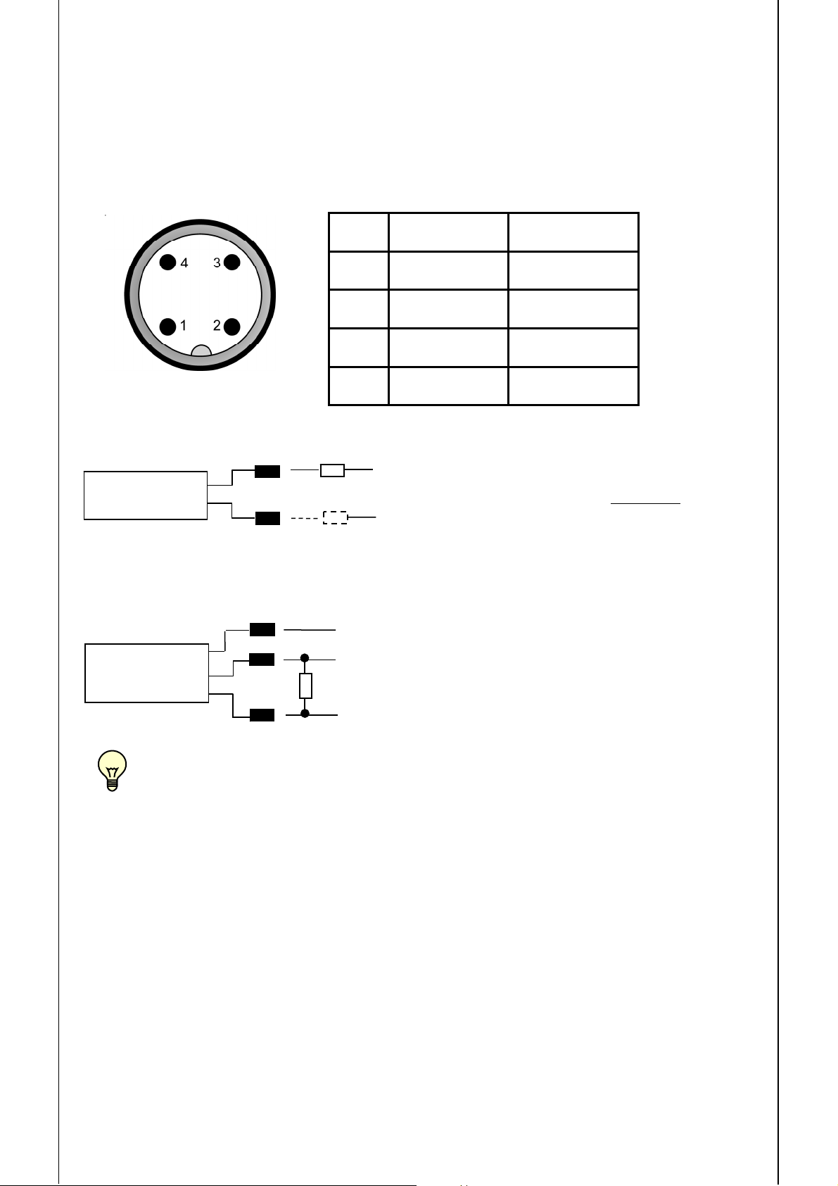
Signalausgang,
zulässige Bürde
4 .. 20 mA, 2 Leiter
RLmax = (UB– 8 V) / 20 mA [kΩ]
0 ..10 V, 3 Leiter
RLmin = 2 kΩ
Genauigkeit nach DIN 16086,
Grenzpunkteinstellung
± 0,5 % FS typ.
± 1,0 % FS max.
Genauigkeit bei Kleinstwerteinstellung
(B.F.S.L.)
± 0,25 % FS typ.
± 0,5 % FS max.
Temperaturkompensation
Nullpunkt
± 0,015 % FS / °C typ.
± 0,025 % FS / °C max.
Temperaturkompensation
Spanne
± 0,015 % FS / °C typ.
± 0,025 % FS / °C max.
Nicht-Linearität bei Grenzpunkteinstellung
nach DIN 16086 ≤± 0,3 % FS max.
Hysterese ≤± 0,4 % FS max.
Wiederholbarkeit ± 0,1 % FS
Anstiegszeit 2 ms
Langzeitdrift ± 0,3 % FS typ. / Jahr
Umgebungsbedingungen
Kompensierter Temperaturbereich -25 .. +85 °C
Betriebstemperaturbereich 1) -40 .. +85 °C / -25 .. +85 °C
Lagertemperaturbereich -40 .. +100 °C
Mediumstemperaturbereich 1) -40 .. +100 °C / -25 .. +100 °C
- Zeichen EN 61000-6-1 / 2 / 3 / 4
-Zeichen 2) Zertifikat-Nr.: E318391
Vibrationsbeständigkeit nach
DIN EN 60068-2-6 bei 10 ..500 Hz 20 g
Schutzart nach DIN EN 60529 3) IP 67 (M12x1 Stecker, bei Verwendung
einer IP 67 Kupplungsdose)
Sonstige Größen
Versorgungsspannung 2-Leiter
bei Einsatz gemäß UL-Spezifikation
8 .. 30 V DC 2-Leiter
12 .. 30 V DC 3-Leiter
-limited energy- gemäß 9.3 UL 61010,Class2;
UL 1310/1585;LPS UL 60950
Restwelligkeit Versorgungsspannung ≤5 %
Stromaufnahme 3-Leiter < 25 mA
Lebensdauer > 10 Mio. Lastwechsel
0 .. 100 % FS
Gewicht ca. 60 g