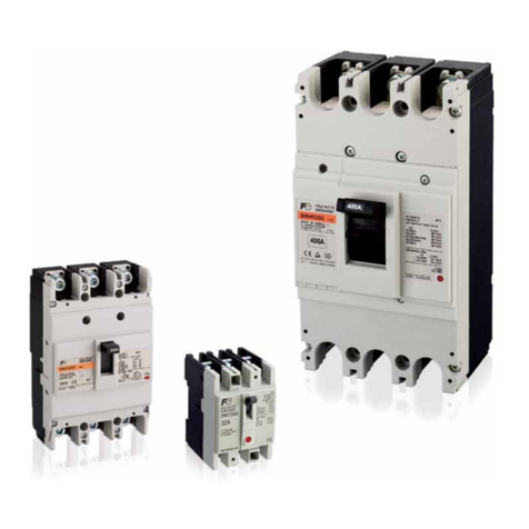
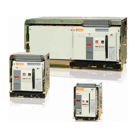
Fuji Electric BW32AAG Manual

DISTRIBUTION
Molded Case Circuit Breakers & Earth Leakage Circuit Breakers
Technical information
62D4-E-0058


CONTENTS
Chapter 1Protecting low-voltage circuits
1-1 Description ...................................................................... 4
1-2 Overcurrent protection .................................................... 5
1-3 Phase-loss protection ..................................................... 6
Chapter 2Operating characteristics and
performance
2-1 Overcurrent tripping characteristics ................................ 8
2-2 Breaking performance .................................................. 11
2-3 Overload switching performance .................................. 26
2-4 Performance with current at 100% ................................ 27
2-5 Durability ....................................................................... 29
2-6 Withstand voltage performance .................................... 31
2-7 Handle operating force and angle ................................. 32
Chapter 3Selection and application
3-1 Selection check points .................................................. 34
3-2 Cascade trip applications ............................................. 40
3-3 Selective trip applications ............................................. 43
3-4 Wiring protection ........................................................... 52
3-5 Motor circuit applications .............................................. 57
3-6 Applications on the primary side of transformers ......... 63
3-7 Welder circuit applications ............................................ 66
3-8 Selecting an MCCB for capacitor circuit ....................... 69
3-9 MCCBs for semiconductor circuit ................................. 73
3-10 Protecting SSCs using MCCBs or MMSs .................... 77
3-11 Protecting inverter circuits using MCCBs .................... 79
3-12 MCCBs for high frequency circuits .............................. 80
3-13 MCCBs for DC circuit applications .............................. 81
3-14 MCCBs for UPS applications ....................................... 83
3-15 MCCBs for servo amplifier applications ....................... 84
3-16 Ground fault protection in system applications ............ 85
Chapter 4Environment and usage
precautions
4-1 Standard conditions ...................................................... 90
4-2 Application to special environments ............................. 91
4-3 Connection precautions ................................................ 93
4-4 Malfunction due to transient inrush current .................. 94
Chapter 5Maintenance inspections
5-1 Faults and causes ......................................................... 96
5-2 Periodic inspections ...................................................... 98
5-3 Replacement recommendations ................................. 100
Chapter 6Short-circuit current calculation
6-1 Calculating short-circuit current .................................. 102
Glossary ....................................................................... 106

Introduction
FUJI has employed its comprehensive technical expertise to bring a complete
range of models and features to its line of molded case circuit breakers (MCCBs),
the mainstay for low-voltage overcurrent protection devices.
A more complete line of breakers is combined with better performance and
greater economy to yield a wider selection of products than ever before. Now
with superior applicability, operability and safety, MCCBs have firmly established
their place in the world of overcurrent protection devices for low-voltage circuits.
In response to customer needs, this product line represents some of the safest
and most economical protection systems available. This Technical Information
contains the data that is needed for selecting the most appropriate FUJI MCCB.
It is provided to help you design superior equipment that is safe and cost efficient.

3
Chapter 1
CONTENTS
Protecting low-voltage
circuits
1-1 Description ................................................................................................................4
1-2 Overcurrent protection
1-2-1 Overcurrent fault.............................................................................................................5
1-2-2 Overcurrent protection....................................................................................................5
1-3 Phase-loss protection
1-3-1 Phase-loss fault...............................................................................................................6
1-3-2 Phase-loss burnout protection (three-phase circuit) .......................................................6

4
1Protecting low-voltage circuits
1-1 Description
1-1 Description
The most common faults occurring with low-voltage circuits
are overcurrent (resulting from overload or short-circuit),
ground faults, and phase-loss. A device that will protect
equipment from these faults is therefore needed for reliable
and economical operation. The following section describes
lowvoltage circuit faults along with measures to protect against
them.

5
1
Protecting low-voltage circuits
1-2 Overcurrent protection
1-2-1 Overcurrent fault
Overcurrent occurs when a circuit is exposed to current that
is higher than the rated load current. It may be due to short
circuiting in a circuit or to overloading that occurs when a
motor overloads or the rotor locks. In either case, overcurrent
can damage cables, and switching devices and load
equipment connected to a faulty circuit, and can easily spread
to other systems. Overcurrent protection devices are installed
to protect cables and other devices connected to a faulty
circuit while minimizing damage to systems beyond the circuit.
1-2-2 Overcurrent protection
(1) Overload protection
When overcurrent caused by motor overload or a locked
rotor reaches as much as six times the motor rated current, it
results in thermal damage. A circuit breaker is used to ensure
quick tripping to protect the connected devices – the breaker
having a lower operating characteristic curve than the heating
characteristic curves of the motor winding and cable.
(2) Short-circuit protection
Since short-circuit current is caused by a short in a circuit,
it tends to be fairly large. The actual amount is calculated
from the power supply capacity, power supply voltage, and
cable impedance to the shorting point. It can vary significantly
with low-voltage circuits from near the rated load current to
several hundred times the rated load current depending on the
shorting point. This has prompted studies first to find circuit
breakers with rated capacities that can handle massive short-
circuit current, and second to look into materials that can
protect against the electromagnetic forces generated by the
shortcircuit current peak value Isp and the joule integral (I2t) in
circuits before the breaker cuts current off completely.

6
1Protecting low-voltage circuits
1-3 Phase-loss protection
1-3-1 Phase-loss fault
(1) Three-phase power supply circuit
A phase-loss fault occurs when there is a disconnection in one
of the phase wires. If a motor continues running under those
conditions, the result is an imbalance in the current flow to the
motor windings that can generate enough heat to burn out the
windings. This can develop eventually into a short-circuit or
ground fault.
A phase-loss protection device protects the motor windings
from burning and prevents the fault from developing into a
wider problem.
1-3-2 Phase-loss burnout protection
(threephase circuit)
One way to prevent phase-loss from burning the motor or
severely lowering its durability is to disconnect it from the
circuit. For economic reasons, it is recommend that this be
done using a manual motor starter (MMS) with phase-loss
protection capability.

7
Chapter 2
CONTENTS
Operating characteristics
and performance
2-1 Overcurrent tripping characteristics
2-1-1 Types of tripping ............................................................................................................8
2-1-2 Factors affecting overcurrent trip characteristics ...........................................................8
2-2 Breaking performance
2-2-1 Short-circuit current breaking ......................................................................................11
2-2-2 Breaking characteristics ..............................................................................................12
2-2-3 Arc space ....................................................................................................................13
2-2-4 Reset time ...................................................................................................................25
2-3 Overload switching performance .................................................................26
2-4 Performance with current at 100%
2-4-1 Temperature rise .........................................................................................................27
2-4-2 Internal resistance and power consumption ................................................................27
2-5 Durability
2-5-1 Switching durability ......................................................................................................29
2-5-2 Trip switching durability ...............................................................................................29
2-5-3 Rated ultimate short-circuit breaking performance .....................................................29
2-5-4 Switching durability of accessories ..............................................................................30
2-6 Withstand voltage performance
2-6-1 Rated power frequency withstand voltage (IEC 60947-1, 2) .......................................31
2-6-2 Rated impulse withstand voltage (IEC 60947-1, 2) .....................................................31
2-7 Handle operating force and angle ................................................................32

8
2Operating characteristics and performance
2-1 Overcurrent tripping characteristics
(3) Short-time delay trip
This type of tripping has a short-time delay to handle the
selective trip coordination of low-voltage circuits.
2-1-2 Factors affecting overcurrent trip
characteristics
There are basically three types of overcurrent tripping:
thermalmagnetic, hydraulic-magnetic and solid-state. The
effect of each varies with the principle involved.
Table 2-1 shows models organized by the type of trip device.
Table 2-1 Breaker trip devices
Trip device MCCB type ELCB type (Reference)
Thermal-
magnetic
The following models not
included.
The following models not
included.
Hydraulic-
magnetic
BW32AAG, BW32SAG
BW50AAG, BW50EAG
BW50SAG, BW50RAG
BW63EAG, BW63SAG
BW63RAG
BW100AAG
BW100EAG
EW32AAG, EW32EAG
EW32SAG
EW50AAG, EW50EAG
EW50SAG, EW50RAG
EW63EAG, EW63SAG
EW63RAG
EW100AAG
EW100EAG
Solid state BX100, BX160
BX250, BX400
BX630, BX800
BX1000
BX1250
BX1600
BW1000RAE
BW1250RAE
BW1600RAE
(1) Ambient temperature
If an MCCB is used at a temperature other than the
reference ambient temperature at which its overcurrent
trip characteristics are prescribed, the long-time delay trip
characteristic changes. Therefore, the choice of MCCB must
consider the cataloged temperature correction curve and
overcurrent trip characteristics. As Table 2-2 shows, the effects
of ambient temperature on the overcurrent trip characteristics
of an MCCB vary according to the type of trip device.
Table 2-2 Ambient temperature effects on overcurrent trip
Trip device Effect of ambient temperature change
Thermalmagnetic The minimum current for trip operation will
decrease when the ambient temperature exceeds
the reference ambient temperature, and vice
versa. This means that a lower overcurrent makes
the bimetal reach the operating temperature
as the ambient temperature rises, because the
bimetal’s operating temperature is constant.
Hydraulicmag-
netic
Although the minimum value of trip current
remains unchanged, the operating time varies
depending on the ambient temperature, as the
viscosity of silicon fluid in the oil dashpot varies.
2-1 Overcurrent tripping characteristics
2-1-1 Types of tripping
Overcurrent tripping in MCCBs occurs in three different ways
depending on the amount of overcurrent. For line protection
use in general, the breakers use an inverse-time delay trip and
instantaneous trip (dual trip-element characteristic).
Some breakers use a short-time delay in addition to the
inverse-time delay trip and the instantaneous trip mainly for
selective trip coordination. This is particularly true with larger
breakers (ternary trip-element characteristic).
Fig. 2-1 shows a dual trip-element characteristic curve while
Fig. 2-2 shows a ternary trip-element characteristic curve.
(1) Inverse-time delay trip (long-time delay)
This type of tripping delays the tripping time of the breaker at
a rate inversely proportional to the amount of overcurrent. It is
available as either a thermal-magnetic type that uses ordinary
bimetal elements or as a hydraulic-magnetic type that uses oil
dashpot damping. The trip is also referred to as a long-time
delay trip to distinguish it from the shorter tripping time of the
short-time delay trip.
(2) Instantaneous trip
This trips the circuit breaker immediately when there is
relatively significant overcurrent like short-circuit current.
Fig. 2-1 Dual trip-element characteristic
Inverse time-delay trip (Long-time delay trip)
Instantaneous trip
Operating time
Current
Fig. 2-2 Ternary trip-element characteristic
Inverse time-delay trip (Long-time delay trip)
Short-time delay trip
Instantaneous trip
Operating time
Current

9
2
Operating characteristics and performance
2-1 Overcurrent tripping characteristics
Table 2-4 Current rating correction for hydraulic-magnetic MCCB by mounting angle
Mounting angle Vertical * Horizontal Horizontal
(upside
down)
Slant 15°
(backward)
Slant 45°
(backward)
Slant 15°
(forward)
Slant 45°
(forward)
Rated current
correction factor
MCCB ELCB (Reference)
BW32AAG, BW32SAG
BW50AAG, BW50EAG
BW50SAG, BW50RAG
BW63EAG, BW63SAG
BW63RAG
BW100AAG
BW100EAG
EW32AAG, EW32EAG
EW32SAG
EW50AAG, EW50EAG
EW50SAG, EW50RAG
EW63EAG, EW63SAG
EW63RAG
EW100AAG
EW100EAG
100% 85% 115% 95% 90% 105% 110%
Note: * A 100% rated current correction factor is maintained on a vertical line at any angle as shown in the figure below.
ON
ONOFFOFFON OFF
OFF
ON
View from P
ON P
OFF
ON OFF
ON OFF
ON
OFF
ON ON
OFF
ON
OFF
(4) Mounting angle effects
Special care must be taken regarding the mounting angle
of MCCBs because the angle will affect their operating
characteristics. In a hydraulic-magnetic type, for example, the
operating current varies with the mounting angle because
gravity affects the plunger in the oil dashpot.
(3) Mounting angle
MCCBs are designed to be mounted in parallel with the
vertical plate. Note that different mounting other than
the standard position could alter the MCCB’s operating
characteristic (see Table 2-4). The effect of mounting angle on
the overcurrent trip characteristic varies depending on the type
of trip device as shown in Table 2-3.
Table 2-3 Effect of mounting angle on overcurrent trip
Trip device Effect of mounting angle
Thermalmagnetic Although the heat radiation is slightly dependent
on mounting angle, the operating characteristic
is hardly affected by it. Therefore, the effect of
mounting angle is negligible.
Hydraulicmag-
netic
The gravity on the iron core in the cylinder varies
depending on the mounting angle. The mounting
angle, then, affects the operating characteristics.
In general, a backward or forward tilt not
exceeding the angle of 10° from the vertical plate
has negligible effect. A larger angle than this
needs the current rating correction as indicated in
the Table 2-4.
(2) Hot-start and cold-start
The cataloged characteristic curve that is called the cold-start
characteristic represents the operating characteristic of an
MCCB that has just been energized at the reference ambient
temperature. The MCCB’s operating characteristic appearing
when overcurrent has just begun to flow after a long period of
steady load current is called the hot-start characteristic.
In general, 50% or 75% of the rated load current is used
as the steady state load current, and the associated
operating characteristics are called the 50% or 75% hot-
start characteristics. With both thermal-magnetic and
hydraulicmagnetic type MCCBs, the hot-start operating time is
shorter than the cold-start operating time as shown in Fig. 2-3.
Fig. 2-3 Hot and cold start characteristics
Cold start
Hot start
Operating time
Current

10
2Operating characteristics and performance
2-1 Overcurrent tripping characteristics
(c) High frequency
For operation at higher frequencies, such as 400 or 750Hz,
the current rating of a thermal-magnetic MCCB has to be
derated due to the heat generated by the skin effect in the
conductors or the eddy current in the iron core. The rate of
reduction slightly depends on the ampere-frame size and the
rated current. The available current rating at 400Hz decreases
to 70–80% of the rated current.
As the iron loss lowers the attractive force of the trip device,
the instantaneous trip current will increase. Hydraulic-magnetic
MCCBs cannot be used in a high-frequency circuit because
the operating characteristics will change greatly due to the
temperature rise of the moving iron core and the reduced
attractive force by the high frequency.
Table 2-5 Operating characteristic changes for DC circuit application
Trip device Inverse time-delay trip characteristic Instantaneous trip characteristics Operating characteristic curve
Thermal-magnetic None The instantaneous trip current is
higher than that for an AC circuit.
The rate of variation depends
on the ampere-frame size, rated
current and model. The trip current
can be as high as 140% of the AC
value.
AC
DC
Current
Operating time
Hydraulic-magnetic The minimum operating current at DC
is about 110–140% of that for AC.
AC
DC
Current
Operating time
Solid state Not applicable
(5) Frequencies
(a) Commercial frequencies (50Hz, 60Hz)
The characteristics of breakers are generally the same at 50
and 60Hz.
(b) Direct current (DC)
If an MCCB designed for operation in an AC circuit were used
in a DC circuit, its operating characteristics would change as
shown in Table 2-5. Hence, an MCCB exclusively designed for
operation in a DC circuit has to be used on this occasion.

11
2
Operating characteristics and performance
2-2 Breaking performance
Fig. 2-5 Three-phase short-circuit current breaking test
oscillograms 460V AC, 3-phase
Supply voltage
L1phase voltage
14.9 kA
39.5 kA
43.0 kA
Current-limiting type
Non current-limiting type
69.7 kA
65.6 kA
78.2 kA
L1phase current
L2phase voltage
L2phase current
L3phase voltage
L3phase current
2 2 460 V
2 2 460 V
Supply voltage
L1phase voltage
L1phase current
L2phase voltage
L2phase current
L3phase voltage
L3phase current
2-2 Breaking performance
2-2-1 Short-circuit current breaking
Fig. 2-4 illustrates how a short-circuit current is broken.
Fig. 2-4 Short-circuit current breaking
Current
Voltage
Arc voltage
Arcing time
Restrike voltage
Recovery voltage
Available short-circuit current
Time to open contact
Total opening time
Beginning of
short-circuit fault
Actual short-circuit current
to be broken
When a short-circuit fault occurs and a short-circuit current
flows, the instantaneous trip device is actuated to quickly open
the contacts. An arc is generated between the contacts the
moment the moving contact separates from the stationary
contact.
The rapid movement of the moving contact away from the
stationary contact draws the arc rapidly across the arc horn
and into the arc quencher. The arc lengthens as the distance
between the contacts increases, until the electromotive force
generated between the grid and arc current drives the arc
deeply into the V-notches in the magnetic sheets composing
the arc quencher’s grid. The grid thus splits the arc into a
series of shorter arcs. With the arc stretched and split up in
this way, the resistance and the arc voltage increase due to
the combined action of cooling by the grid, the rising pressure
in the arc quencher, and the cathode effect. The arc is
extinguished (quenched) when the arc voltage becomes larger
than the supply voltage. At this time, a voltage equivalent
to the supply voltage (recovery voltage) appears across the
contacts. This condition is called completion of breaking.
In general, a circuit in which a large short-circuit current
occurs has a low power factor. If the arc is quenched
at the zerocrossing point of the short-circuit current, a
circuit-constant, dependent oscillating transient voltage is
superimposed on the recovery voltage that appears across
the contacts. This voltage is called the restrike voltage and
can cause rearcing between the contacts if the isolation
between the contacts has not recovered sufficiently. To achieve
complete breaking without rearcing, powerful arc-quenching
action and sufficient contact spacing must be ensured quickly.
To achieve current-limiting breaking, current-limiting MCCBs
use the electromotive force generated across two parallel
conductors to quickly open the contacts without waiting for
instantaneous trip, while increasing the arc voltage in an
extremely short time. In DC circuits, the current does not fall
to zero as in AC circuits. The arc voltage must be increased
through a powerful arc quenching effect to suppress the
current: arc quenching is complete when the supply of energy
needed to maintain arcing is no longer available.
Fig. 2-5 shows the three-phase short-circuit current breaking
test oscillograms.

12
2Operating characteristics and performance
2-2 Breaking performance
2-2-2 Breaking characteristics
(1) Breaking performance
The characteristics that define MCCB breaking performance
are the rated short-circuit breaking capacity, peak let-through
current, and maximum let-through I2t. The rated short-circuit
breaking capacity is defined by the rated ultimate short-circuit
breaking capacity (Icu), and the rated service short-circuit
breaking capacity (Ics).
(2) Rated short-circuit breaking capacity
Fig. 2-6 is a typical oscillogram of a short-circuit current. In the
figure, t=0 denotes the time the short-circuit fault occurred.
The rated load current was flowing at the supply voltage before
the short-circuit fault occurred. The current by several factors
of ten flows after the occurrence of the short circuit. Because
the load current immediately after the short-circuit fault
contains a DC component, the current flow is asymmetrical
with respect to the zero-current line, with the DC component
being attenuated rapidly. The curve C-C’ represents the DC
component of the asymmetrical short-circuit current, and is
indicates the current that would flow if a short circuit occurred.
This current is called the available short-circuit current.
iS=iAC+iDC=Im[sin (Zt+ø−M)−e L
Rt
−sin (ø−M)]
ø: Making phase angle
cosM: Short-circuit power factor
The value of the above equation reaches
its maximum when (ø−M) = ± .
Im= R
2
+(ZL)
2
√
Em2
π
Fig. 2-6 Short-circuit current oscillogram
1/2 cycle
i
A
B
C
X
Y
P
iS
P'
A'
C'
B'
t
0
i
iS: Short-circuit current
C-C': Intermediate line between the envelopes A-A' and B-B'
P-P': 1/2 cycle after occurrence of short-circuit fault
X: AC component of short-circuit current
Y: DC component of short-circuit current
The rated breaking current of an MCCB is represented as
X/
√2
, the effective value of the AC component 1/2 cycle after
the occurrence of the short-circuit fault. For a three-phase
circuit, the rated breaking current is represented the average
of
the three phases.
For DC circuits, the maximum available short-circuit current is
used.
(3) Operating duty
Under conditions where the displayed rated breaking capacity
is specified, breakers will break properly at an operating duty
of “O” -t- “CO” for Icu and “O” -t- “CO” -t- “CO” for Ics (where
t is three minutes or the time it takes to reset the breaker,
whichever is longer). All this is done at the rated voltage and
frequency. After the breaker trips, however, the rated current
may or may not flow, but the breaking capacity, durability,
letthrough current and overload switching capacity will be
diminished. Therefore, replace the breaker with a spare as
quickly as possible. If current must be supplied with the same
breaker, conduct a maintenance inspection that looks closely
at the operating conditions prior to the breaker tripping, the
amount of short-circuit current, as well as future operating
conditions. Special attention must be paid to temperature rise
as well.

13
2
Operating characteristics and performance
2-2 Breaking performance
(5) Maximum let-through current and maximum
breaking I2t
The current that would flow through a short circuit without a
circuit breaker is called the available short-circuit current. It is
the short-circuit current that is determined from the impedance
map at circuit breaker selection, not the current that is actually
interrupted by the circuit breaker. The current that actually
flows through the circuit is smaller than the available short-
circuit current. As the trip device in the circuit breaker is
actuated to open the contact immediately on occurrence of a
short circuit, the arc voltage is increased to inhibit current flow.
This is equivalent in effect to having a variable resistor, called
an arc resistor, connected in series in the circuit.
Current-limiting circuit breakers that take advantage of the
magnetic repulsion force represent an application of this
principle; current-limiting breaking is done before the short-
circuit current reaches its peak value.
The maximum current that can flow through the circuit breaker
is called the maximum let-through current, which is expressed
as a peak value. The smaller the maximum let-through current,
the less mechanical stress is imposed on the cable and load
equipment. With a high short-circuit current having a low
power factor, the transient peak value is more than twice the
symmetrical effective value. In mechanical stress studies,
therefore, a choice must be made between the current-
limiting type and the non-current-limiting type, along with full
allowance for electromotive force.
The squared product of the let-through current, or ∫
t2
t1i2dt from
t1 short-circuit occurrence time t1 to completion of breaking
time t2, is called the maximum breaking I2t. The smaller this
value, the smaller the thermal effects on the cable and load
equipment. Fig. 2-8 to 2-9 and Fig. 2-10 to 2-11 give the
maximum let-through I2t or maximum let-through current, and
available short-circuit current of MCCBs.
2-2-3 Arc space
When a short-circuit current is broken, an ionized gas is
emitted from the breaker’s line side exhaust vent and, because
this gas is conductive, it could induce an interphase short
circuit or ground fault if it bridges adjacent bare live parts or
a bare live part and an adjacent grounded metallic surface.
Because this is potentially hazardous, an arc space (insulation
space) is required for safety.
Table 2-7 lists the arc spaces required for specific conditions.
When wiring is done, live parts should be either taped or
protected by insulating barriers in the ranges specified in
Table 2-7 to allow for conditions that could be encountered
while the MCCB is in service. Improved insulation may be
needed outside the arc space depending on the service
conditions of the MCCB.
Fig. 2-7 Current breaking process
Load current
Total opening time
Arcing time
Arc voltage
Recovery voltage
Available short-circuit current
Short-circuit occurrence
Time
Restrike voltage
Current
Contact
opening
time
Breaking
current
Maximum peak
let-through current
Maximum peak available
short-circuit current
Zero-crossing point of
short-circuit current
Short-circuit current
breaking point
(4) Breaking characteristics
When the magnitude of an overcurrent exceeds a certain
limit, the instantaneous trip device is actuated to open the
pole immediately. The minimum current that can actuate the
instantaneous trip device is called the instantaneous trip
current, which is expressed as a symmetrical effective value.
With thermal-magnetic MCCBs, the instantaneous trip current
setting is adjustable because their instantaneous trip device
is installed separately from the inverse time-delay trip device.
This eases coordination with other devices. Fig. 2-7 shows
the progress of time after the start of short-circuit current
flow until completion of breaking. The time interval between
the occurrence of a short-circuit fault and the opening of the
contacts is called the contact opening time. The time interval
between completion of breaking and quenching of the arc
generated by contact opening is called the arcing time. The
sum of the contact opening time and the arcing time, or the
period of time from the occurrence of a short-circuit fault to
completion of breaking, is called the total opening time. Table
2-7 lists the contact opening times, arcing times, and total
opening times of MCCBs at breaking of the rated breaking
current.

14
2Operating characteristics and performance
2-2 Breaking performance
Fig. 2-8 Max. let-through I2t 230V AC
0.1
0.2
0.3
0.5
0.8
1
2
3
5
8
10
20
30
50
80
100
0.01
0.02
0.03
0.05
0.08
(0.13) 3.5mm2
(0.21) 4mm2
(0.05) 2mm2
(0.082) 2.5mm2
(0.4) 5.5mm2
(0.471) 6mm2
(1.05) 8mm2
(1.31) 10mm2
(2.7) 14mm2
(3.35) 16mm2
(6.8) 22mm2
(8.18) 25mm2
(12) 30mm2
(16)* 35mm2
21 5 10 20 50 100 200 500 1000
BW630EAG, RAG, HAG
EW630EAG, RAG, HAG
BW630RAGU, HAGU
EW630RAGU
BW800EAG, RAG, HAG
EW800EAG, RAG, HAG
BW800RAGU, HAGU
BW400EAG, SAG, RAG, HAG
EW400EAG, SAG, RAG, HAG
BW400EAGU, SAGU, RAGU, HAGU
EW400SAGU, RAGU, HAGU
BW250JAG, RAG, HAG
EW250JAG, RAG, HAG
BW250JAGU, RAGU
EW250JAGU, RAGU
BW50HAG (40, 50A)
EW50HAG (40, 50A)
BW125JAG, RAG, HAG (40 to 125A)
EW125JAG, RAG, HAG (40 to 125A)
BW125JAGU, RAGU (40 to 125A)
EW125JAGU, RAGU (40 to 125A)
BW50HAG (30A)
EW50HAG (30A)
BW125JAG, RAG, HAG (30A)
EW125JAG, RAG, HAG (30A)
BW125JAGU, RAGU (30A)
EW125JAGU, RAGU (30A)
BW50HAG (20A)
EW50HAG (20A)
BW125JAG, RAG, HAG (20A)
EW125JAG, RAG, HAG (20A)
BW125JAGU, RAGU (20A)
EW125JAGU, RAGU (20A)
BW50HAG (15A)
EW50HAG (15A)
BW125JAG, RAG, HAG (15A)
EW125JAG, RAG, HAG (15A)
BW125JAGU, RAGU (15A)
EW125JAGU, RAGU (15A)
BW50, 63RAG
BW100EAG
EW50, 63RAG
EW100, EAG, EAD
BW50RAGU
BW100EAGU
EW50RAGU
EW100EAGU
BW250EAG, EAGU
BW50, 63SAG
EW50, 63SAG
BW32SAG
BW50, 63EAG
BW100AAG
EW32SAG
EW50, 63EAG
EW100AAG
BW32, 50AAG
EW32, 50AAG
BW50, 63EBG
EW50, 63EBG
BW32, 50, 63SBG
EW32, 50, 63SBG
BW50RBGU
EW50RBGU
J
J
J
R
R
R
H
J
RH
J
RH
E
E
E
SRH
RH
H
H
Max. let-through current
ò i2dt (x106A2s)
Available short-circuit current (rms. sym.) (kA)
Note: * The parentheses ( ) indicate approximate tolerances I2t for each wire gauge. (See Table 3-11, Chapter 3.)

15
2
Operating characteristics and performance
2-2 Breaking performance
Fig. 2-9 Max. let-through I2t 400V AC
0.1
0.2
0.3
0.5
0.8
1
2
3
5
8
10
20
30
50
80
100
0.01
0.02
0.03
0.05
0.08
(0.13) 3.5mm2
(0.21) 4mm2
(0.05) 2mm2
(0.082) 2.5mm2
(0.4) 5.5mm2
(0.471) 6mm2
(1.05) 8mm2
(1.31) 10mm2
(2.7) 14mm2
(3.35) 16mm2
(6.8) 22mm2
(8.18) 25mm2
(12) 30mm2
(16)* 35mm2
21 5 10 20 50 100 200 500 1000
BW630EAG, RAG, HAG
EW630EAG, RAG, HAG
BW630RAGU, HAGU
EW630RAGU
BW800EAG, RAG, HAG
EW800EAG, RAG, HAG
BW800RAGU, HAGU
BW400EAG, SAG, RAG, HAG
EW400EAG, SAG, RAG, HAG
BW400EAGU, SAGU, RAGU, HAGU
EW400SAGU, RAGU, HAGU
BW250JAGU, RAGU
EW250JAGU, RAGU
BW250JAG, RAG, HAG
EW250JAG, RAG, HAG
BW50HAG (40, 50A)
EW50HAG (40, 50A)
BW125JAG, RAG, HAG (40 to 125A)
EW125JAG, RAG, HAG (40 to 125A)
BW125JAGU, RAGU (40 to 125A)
EW125JAGU, RAGU (40 to 125A)
BW50HAG (30A)
EW50HAG (30A)
BW125JAG, RAG, HAG (30A)
EW125JAG, RAG, HAG (30A)
BW125JAGU, RAGU (30A)
EW125JAGU, RAGU (30A)
BW50HAG (20A)
EW50HAG (20A)
BW125JAG, RAG, HAG (20A)
EW125JAG, RAG, HAG (20A)
BW125JAGU, RAGU (20A)
EW125JAGU, RAGU (20A)
BW50HAG (15A)
EW50HAG (15A)
BW125JAG, RAG, HAG (15A)
EW125JAG, RAG, HAG (15A)
BW125JAGU, RAGU (15A)
EW125JAGU, RAGU (15A)
BW50, 63RAG
BW100EAG
EW50, 63RAG
BW50RAGU
BW100EAGU
EW50RAGU
BW250EAG
EW250EAG
BW50, 63SAG
EW50, 63SAG
BW32SAG
BW50, 63EAG
EW32SAG
EW50, 63EAG
BW32, 50AAG
EW32, 50AAG
BW100AAG
BW32, 50, 63SBG
BW32, 50, 63SBG
BW50, 63EBG
EW50, 63EBG
J
J
J
R
R
R
H
H
H
J
J
E
E
S
E
R
R
R
R
H
H
H
H
Max. let-through current
ò i2dt (x106A2s)
Available short-circuit current (rms. sym.) (kA)
Note: * The parentheses ( ) indicate approximate tolerances I2t for each wire gauge. (See Table 3-11, Chapter 3.)

16
2Operating characteristics and performance
2-2 Breaking performance
Fig. 2-10 Peak let-through current 230V AC
Peak let-through current (kA)
2 000100500200105020151
1
2
5
10
20
30
40
50
60
70
80
90
100
200
300
400
500
600
800
1000
J
J
J
S
S
S
R
R
R
H
H
H
J
J
E
E
E
S
S
S
R
R
R
R
H
H
H
H
BW630EAG, RAG, HAG
BW800EAG, RAG, HAG
EW630EAG, RAG, HAG
EW800EAG, RAG, HAG
BW400EAG, SAG, RAG, HAG
EW400EAG, SAG, RAG, HAG
BW250JAG, SAG, RAG, HAG
BW160JAG, SAG, RAG
EW250JAG, SAG, RAG
EW160JAG, SAG, RAG
BW50HAG (40, 50A)
BW125JAG, SAG, RAG, HAG (40 to 125A)
EW125JAG, SAG, RAG (40 to 125A)
BW50HAG (30A)
BW125JAG, SAG, RAG, HAG (30A)
EW125JAG, SAG, RAG (30A)
BW50, 63RAG
BW100EAG
EW50, 63RAG
EW100EAG
BW250EAG
EW250EAG
BW50, 63SAG
EW50, 63SAG
BW32SAG
BW50, 63EAG
BW100AAG
EW32SAG
EW50, 63EAG
EW100AAG
BW32, 50AAG
EW32, 50AAG
BW50HAG (20A)
BW125JAG, SAG, RAG, HAG (20A)
EW125JAG, SAG, RAG (20A)
BW50HAG (15A)
BW125JAG, SAG, RAG, HAG (15A)
EW125JAG, SAG, RAG (15A)
Unlimited

17
2
Operating characteristics and performance
2-2 Breaking performance
Fig. 2-11 Peak let-through current 400V AC
Peak let-through current (kA)
2
5
10
20
30
40
50
60
70
80
90
100
200
300
400
500
600
800
1000
J
J
J
J
J
E
E
S
S
S
S
S
S
E
R
R
R
R
R
R
R
H
H
H
H
H
H
H
BW630EAG, RAG, HAG
BW800EAG, RAG, HAG
EW630EAG, RAG, HAG
EW800EAG, RAG, HAG
BW400EAG, SAG, RAG, HAG
EW400EAG, SAG, RAG, HAG
BW250JAG, SAG, RAG, HAG
BW160JAG, SAG, RAG
EW250JAG, SAG, RAG
EW160JAG, SAG, RAG
BW50HAG (40, 50A)
BW125JAG, SAG, RAG, HAG (40 to 125A)
EW125JAG, SAG, RAG (40 to 125A)
BW50HAG (30A)
BW125JAG, SAG, RAG, HAG (30A)
EW125JAG, SAG, RAG (30A)
BW50, 63RAG
BW100EAG
EW50, 63RAG
EW100EAG
BW250EAG
EW250EAG
BW50, 63SAG
EW50, 63SAG
BW32SAG
BW50, 63EAG
BW100AAG
EW32SAG
EW50, 63EAG
EW100AAG
BW32, 50AAG
EW32, 50AAG
BW50HAG (20A)
BW125JAG, SAG, RAG, HAG (20A)
EW125JAG, SAG, RAG (20A)
BW50HAG (15A)
BW125JAG, SAG, RAG, HAG (15A)
EW125JAG, SAG, RAG (15A)
Unlimited

18
2
Current and energy limiting curves
Ics = 100 % Icu
The exceptional limiting capacity of the BX range greatly
reduces the forces created by fault currents in devices.
The result is a major increase in breaking performance.
In particular, the service breaking capacity Ics is equal to 100
% of Icu.
The Ics value, defined by IEC standard 60947-2, is guaranteed
by tests comprising the following steps:
break three times consecutively a fault current equal to 100
% of Icu
check that the device continues to function normally, that is:
it conducts the rated current without abnormal temperature
rise
protection functions perform within the limits specified by the
standard
suitability for isolation is not impaired.
Longer service life of electrical installations
Current-limiting circuit breakers greatly reduce the negative
effects of short-circuits on installations.
Thermal effects
Less temperature rise in conductors, therefore longer service life for
cables.
Mechanical effects
Reduced electrodynamic forces, therefore less risk of electrical
contacts or busbars being deformed or broken.
Electromagnetic effects
Fewer disturbances for measuring devices located near electrical
circuits.
Economy by means of cascading
Cascading is a technique directly derived from current
limiting. Circuit breakers with breaking capacities less than the
prospective short-circuit current may be installed downstream
of a limiting circuit breaker. The breaking capacity is reinforced
by the limiting capacity of the upstream device. It follows that
substantial savings can be made on downstream equipment
and enclosures.
Current and energy limiting curves
The limiting capacity of a circuit breaker is expressed by two
curves which are a function of the prospective short-circuit
current (the current which would flow if no protection devices
were installed):
the actual peak current (limited current)
thermal stress (A2s), i.e. the energy dissipated by the short-
circuit in a conductor with a resistance of 1 :.
Example
What is the real value of a 150 kA rms prospective short-circuit (i.e.
330 kA peak) limited by an BX250L upstream ?
The answer is 30 kA peak (curve page 19).
Maximum permissible cable stresses
The table below indicates the maximum permissible thermal
stresses for cables depending on their insulation, conductor (Cu
or Al) and their cross-sectional area (CSA). CSA values are
given in mm² and thermal stresses in A2s.
CSA 1.5 mm² 2.5 mm² 4 mm² 6 mm² 10 mm²
PVC Cu 2.97x1048.26x1042.12x1054.76x1051.32x106
Al 5.41x10⁵
PRC Cu 4.10x1041.39x1052.92x1056.56x1051.82x106
Al 7.52x10⁵
CSA 16 mm² 25 mm² 35 mm² 50 mm²
PVC Cu 3.4x1068.26x1061.62x1073.31x107
Al 1.39x1063.38x1066.64x1061.35x107
PRC Cu 4.69x1061.39x1072.23x1074.56x107
Al 1.93x1064.70x1069.23x1061.88x107
Example
Is a Cu/PVC cable with a CSA of 10 mm² adequately
protected by an BX160F?
The table above indicates that the permissible stress is
1.32x10⁶ A2s.
All short-circuit currents at the point where an BX160F (Icu =
35 kA) is installed are limited with a thermal stress less than
6x10⁵ A2s (curve page 19).
Cable protection is therefore ensured up to the limit of the
breaking capacity of the circuit breaker.
The limiting capacity of a circuit breaker is its aptitude to let through a
current, during a short-circuit, that is less than the prospective short-
circuit current.
The exceptional limiting capacity of the BX range is due to the rotating
double-break technique (very rapid natural repulsion of contacts and
the appearance of two arc voltages in-series with a very steep wave
front).
(t)
Prospective
Isc peak
(Isc)
Prospective
current
Prospective
Isc
Limited Isc
peak Actual
current
Limited
Isc
Operating characteristics and performance
2-2 Breaking performance
This manual suits for next models
34
Table of contents
Other Fuji Electric Circuit Breaker manuals
Popular Circuit Breaker manuals by other brands

Leviton
Leviton LB1XX-AF SERIES installation instructions

hager
hager hw+ user manual

Westinghouse
Westinghouse DE-ION DH Series Instruction book

Leuze electronic
Leuze electronic MSI-SR-LC21 Series Original operating instructions

Reliance Controls
Reliance Controls WB015 manual

Utility Relay
Utility Relay AC-PRO Retrofit Kit instructions