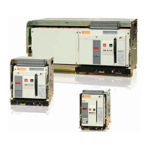
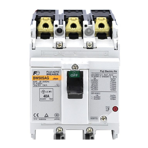
Fuji Electric BW0 Series User manual

DISTRIBUTION
Molded Case Circuit Breakers
BW0 Series
62D1-E-0112b


Compact design
Cost and space saving for
building a control panel.
•Compact size
2P W36×H80×D76(mm)
3P W54×H80×D76(mm)
•AC 440V application
Icu: 1.5kA at 440V AC,
2.5kA at 240V AC
2
Economy series MCCB from 32AF to 400AF
Focusing on assembly of easy wiring, maintenance check, reasonable price, and standardized
distribution board design, BW0 series MCCBs are designed mainly for building construction
market and secondary distribution market.
BW0 series
Compliance to RoHS Directive
All materials used are compliant to RoHS Directive and the main components are easy to
recycle.
32AF
BW253E0 BW403S0BW33A0
Available accessories
• Auxiliary switch
• Alarm switch
• Shunt trip device
W
D
H

BW0
series
3
Compact design
We've applied high-performance technology to achieve 100AF to 250AF models with a
uniform depth of 60mm.
100AF to 400AF
Compliance to RoHS Directive
All materials used are compliant to RoHS Directive and the main components are easy to
recycle.
Cassette type accessories
All accessories can be installed by by the user.
Quickly adaptable to the many onsite changes in
specifications.
Interchangeability
The design of the same external dimensions (400AF) and mounting size (160AF to 400AF)
with G-TWIN circuit breaker.
Just simply change the model when a customer suddenly changes the design (e.g. when
changed to earth leakage circuit breaker).
BW253E0 EW250EAG-3P BW403S0 EW400EAG-3P
InterchangeabilityInterchangeability

4
Catalog Disclaimer
The information contained in this catalog does not constitute an express or implied warranty of quality, any warranty of
merchantability of fitness for a particular purpose is hereby disclaimed.
Since the user's product information, specific use application, and conditions of use are all outside of Fuji Electric FA
Components & Systems'control, it shall be the responsibility of the user to determine the suitability of any of the
products mentioned for the user's application.
One Year Limited Warranty
The products identified in this catalog shall be sold pursuant to the terms and conditions identified in the
"Conditions of Sale" issued by Fuji Electric FA with each order confirmation.
Except to the extent otherwise provided for in the Conditions of Sale issued by Fuji Electric FA, Fuji Electric FA
warrants that the Fuji Electric FA products identified in this catalog shall be free from significant defects in materials and
workmanship provided the product has not been: 1) repaired or altered by others than Fuji Electric FA; 2) subjected to
negligence, accident, misuse, or damage by circumstances beyond Fuji Electric FA's control; 3) improperly operated,
maintained or stored; or 4) used in other than normal use or service. This warranty shall apply only to defects appearing
within one (1) year from the date of shipment by Fuji Electric FA, and in such case, only if such defects are reported
to Fuji Electric FA within thirty (30) days of discovery by purchaser. Such notice should be submitted in writing to Fuji
Electric FA at 5-7, Nihonbashi Odemma-cho, Chuo-ku, Tokyo, Japan. The sole and exclusive remedy with respected to
the above warranty whether such claim is based on warranty, contract, negligence, strict liability or any other theory,
is limited to the repair or replacement of such product or, at Fuji Electric FA's option reimbursement by Fuji Electric FA
of the purchase price paid to Fuji Electric FA for the particular product. Fuji Electric FA does not make any other
representations or warranties, whether oral or in writing, expressed or implied, including but not limited to any
warranty regarding merchantability or fitness for a particular purpose. Except as provided in the Conditions of Sale,
no agent or representative of Fuji Electric FA is authorized to modify the terms of this warranty in writing or orally.
In no event shall Fuji Electric FA be liable for special, indirect or consequential damages, including but not limited to,
loss of use of the product, other equipment, plant and power system which is installed with the product, loss of profits or
revenues, cost of capital, or claims against the purchaser or user of the product by its customers resulting from the use of
information, recommendations and descriptions contained herein. The purchaser agrees to pass on to its customers and
users, in writing at the time inquiries and orders are received by buyer, Fuji Electric FA's warranty as set forth above.

5
Molded Case Circuit Breakers
BW0 Series
Page
Features ............................................................................................................................................................................................ 2
Line up .............................................................................................................................................................................................. 6
Type number nomenclature............................................................................................................................................................... 6
Quick reference guide
32AF............................................................................................................................................................................................ 7
100AF.......................................................................................................................................................................................... 8
160AF.......................................................................................................................................................................................... 9
250AF........................................................................................................................................................................................ 10
400AF........................................................................................................................................................................................ 11
Internal accessories
32AF.......................................................................................................................................................................................... 12
100 to 250AF............................................................................................................................................................................. 13
400AF........................................................................................................................................................................................ 16
External accessories
Operating handle....................................................................................................................................................................... 21
Terminal cover ........................................................................................................................................................................... 22
Insulation barrier Interphase...................................................................................................................................................... 22
Flat terminal............................................................................................................................................................................... 22
Block terminal............................................................................................................................................................................ 22
Handle locking device................................................................................................................................................................ 23
IEC 35mm rail mounting adapter............................................................................................................................................... 23
Terminal connection ........................................................................................................................................................................ 24
Dimensions
MCCBs ...................................................................................................................................................................................... 25
External accessories ................................................................................................................................................................. 30
Characteristic curves....................................................................................................................................................................... 32

6
Molded Case Circuit Breakers
BW0 series
Line up / Type number nomenclature
Line up
Series Breaker
ampere
frame
Type Pole Rated current (A) Insulation
voltage
Ui (V)
Breaking capacity (kA) [Icu/Ics]
IEC60947-2
AC
230V 380V 415V
BW0 32 BW32A0
BW33A0
2
3
5, 10, 15, 20, 32
5, 10, 15, 20, 32
440
440
2.5/2
2.5/2
1.5/1
1.5/1
1.5/1
1.5/1
100 BW103E0
BW102S0
BW103S0
3
2
3
15, 20, 25, 30, 40, 50, 60, 75, 80, 100
15, 20, 25, 30, 40, 50, 60, 75, 80, 100
15, 20, 25, 30, 40, 50, 60, 75, 80, 100
690
690
690
25/13
50/25
100/50
18/9
30/15
30/15
15/8
30/8
30/8
160 BW162E0
BW163E0
BW162J0
BW163J0
BW162S0
BW163S0
2
3
2
3
2
3
100, 125, 150, 160
100, 125, 150, 160
100, 125, 150, 160
100, 125, 150, 160
100, 125, 150, 160
100, 125, 150, 160
690
690
690
690
690
690
25/13
25/13
50/25
50/25
85/43
85/43
18/9
18/9
25/13
25/13
36/18
36/18
18/9
18/9
25/13
25/13
36/18
36/18
250 BW252E0
BW253E0
BW252J0
BW253J0
BW252S0
BW253S0
2
3
2
3
2
3
175, 200, 225, 250
175, 200, 225, 250
175, 200, 225, 250
175, 200, 225, 250
175, 200, 225, 250
175, 200, 225, 250
690
690
690
690
690
690
25/13
25/13
50/25
50/25
85/43
85/43
18/9
18/9
25/13
25/13
36/18
36/18
18/9
18/9
25/13
25/13
36/18
36/18
400 BW402S0
BW403S0
2
3
250, 300, 350, 400
250, 300, 350, 400
690
690
85/43
85/43
36/18
36/18
36/18
36/18
• 32AF
Type number nomenclature
• 100 - 400AF
BW 3 2 A0 - 032 W K FA A
Product category
BW : MCCB
Accessories
Terminal block
A : with terminal block
Shunt trip device *1
FA : 100VAC to 120VAC
FK : 200VAC to 240VAC
FD : 100VDC
Alarm switch *2
K : 1c / alarm switch
Auxiliary switch *2
W : 1c / auxiliary switch
Frame size
3 : 32AF
Number of poles
2 : 2 poles
3 : 3 poles
Rated current
005 : 5A
010 : 10A
015 : 15A
020 : 20A
032 : 32A
Notes
*1 A shunt trip device can be added only to 3-pole models.
*2 Only one of the following can be added to a 2-pole model:
alarm switch or auxiliary switch.
BW 25 3 E0 - 250
Series
Frame size
10 : 100AF
16 : 160AF
25 : 250AF
40 : 400AF
Number of poles
2 : 2-pole
3 : 3-pole
Rated current
15 : 15A
20 : 20A
25 : 25A
30 : 30A
40 : 40A
50 : 50A
60 : 60A
75 : 75A
80 : 80A
100 : 100A
125 : 125A
150 : 150A
160 : 160A
175 : 175A
200 : 200A
225 : 225A
250 : 250A
300 : 300A
350 : 350A
400 : 400A

7
Molded Case Circuit Breakers
BW0 series
Quick reference guide
BW0 series 2, 3-pole IEC and CE marking conformed types
• 32AF
Frame 32A
Pole 2 3
Type BW32A0 BW33A0
Rated current (A) 5, 10, 15, 20, 32
Rated insulation voltage (VAC) 440
[IEC 60947-2] (VDC) −
Rated breaking capacity (kA) 500VAC − −
[IEC 60947-2] 440VAC 1.5/1 1.5/1
(Icu/Ics) *1 415VAC 1.5/1 1.5/1
400VAC 1.5/1 1.5/1
380VAC 1.5/1 1.5/1
240VAC 2.5/1 2.5/1
230VAC 2.5/1 2.5/1
250VDC − −
Rated operating voltage [UL508] (VAC) − −
Dimensions (mm) a 36 54
b 80 80
Page 25 c 60 60
d 76 76
Mass (kg) 0.18 0.25
Tripping device Thermal-magnetic
Front mounting, front connection
Internal accessories Page 12
Auxiliary switch (W)
Alarm switch (K)
Auxiliary switch + alarm switch (W+K) −
Shunt trip (F) −
Undervoltage trip (R) − −
External accessories Page 21
Operating handle N-type − −
Operating handle V-type − −
Terminal cover Short − −
Terminal cover Long BW9BTA0-L2 BW9BTA0-L3
Insulation barrier Interphase − −
Flat terminal − −
Block terminal − −
Handle locking device − −
IEC 35mm rail mounting
Notes: *1 Icu: Rated ultimate short-circuit breaking capacity
Ics: Rated service short-circuit breaking capacity Available Factory mounted accessory − Not available
a d
c
b

8
Molded Case Circuit Breakers
BW0 series
Quick reference guide
BW0 series 2, 3-pole IEC and CE marking conformed types
• 100AF
Frame 100A
Pole 3 2 3
Type BW103E0 BW102S0 BW103S0
Rated current (A) 15, 20, 25, 30, 40, 50, 60,
75, 80, 100
15, 20, 25, 30, 40, 50, 60, 75, 80, 100
Rated insulation voltage (VAC) 690 690
[IEC 60947-2] (VDC) 250 250
Rated breaking capacity (kA) 500VAC 5/3 10/3 10/3
[IEC 60947-2] 440VAC 10/5 20/5 20/5
(Icu/Ics) *1 415VAC 15/8 30/8 30/8
400VAC 15/8 30/15 30/15
380VAC 18/9 30/15 30/15
240VAC 25/13 50/25 100/50
230VAC 25/13 50/25 100/50
250VDC 5/3 5 10
Rated operating voltage [UL508] (VAC) − − −
Dimensions (mm) a 75 50 75
b 130 130 130
Page 26 c 60 60 60
d 81 81 81
Mass (kg) Front mounting type 0.78 0.6 0.78
Tripping device Thermal-magnetic
Front mounting, front connection
Internal accessories Page 13
Auxiliary switch (W) BW9W1SB0 BW9W1SB0 BW9W1SB0
Alarm switch (K) BW9K1SB0 BW9K1SB0 BW9K1SB0
Auxiliary switch + alarm switch (W+K) BW9WKSB0 BW9WKSB0 BW9WKSB0
Shunt trip (F) BW9F
B0 BW9F
B0 BW9F
B0
Undervoltage trip (R) BW9R
B0 BW9R
B0 BW9R
B0
External accessories Page 21
Operating handle N-type BW9N0B0 BW9N0B0 BW9N0B0
Operating handle V-type BW9V0B0 BW9V0B0 BW9V0B0
Terminal cover Short − − −
Terminal cover Long BW9BTB0-L3 − BW9BTB0-L3
Insulation barrier Interphase BW9BPB0 BW9BPB0 BW9BPB0
Flat terminal − − −
Block terminal BW9SSL0B0-
BW9SSL0B0-
BW9SSL0B0-
Handle locking device BW9Q1B0 BW9Q1B0 BW9Q1B0
IEC 35mm rail mounting BW9PDB0 BW9PDB0 BW9PDB0
Notes: *1 Icu: Rated ultimate short-circuit breaking capacity
Ics: Rated service short-circuit breaking capacity
a d
c
b

9
Molded Case Circuit Breakers
BW0 series
Quick reference guide
BW0 series 2, 3-pole IEC and CE marking conformed types
• 160AF
Frame 160A
Pole 2 3 2 3 2 3
Type BW162E0 BW163E0 BW162J0 BW163J0 BW162S0 BW163S0
Rated current (A) 100, 125, 150, 160 100, 125, 150, 160 100, 125, 150, 160
Rated insulation voltage (VAC) 690 690 690
[IEC 60947-2] (VDC) 250 250 250
Rated breaking capacity (kA) 500VAC 5/3 5/3 8/4 8/4 10/5 10/5
[IEC 60947-2] 440VAC 10/5 10/5 20/10 20/10 25/13 25/13
(Icu/Ics) *1 415VAC 15/8 15/8 25/13 25/13 36/18 36/18
400VAC 15/8 15/8 25/13 25/13 36/18 36/18
380VAC 18/9 18/9 25/13 25/13 36/18 36/18
240VAC 25/13 25/13 50/25 50/25 85/43 85/43
230VAC 25/13 25/13 50/25 50/25 85/43 85/43
250VDC 5/3 5/3 20/10 20/10 30/15 30/15
Rated operating voltage [UL508] (VAC) 480 480 480 480 480 480
Dimensions (mm) a 105 105 105 105 105 105
b 165 165 165 165 165 165
Page 27 c 60 60 60 60 60 60
d 86 86 86 86 86 86
Mass (kg) Front mounting type 1.36 1.36 1.36 1.56 1.36 1.56
Tripping device Thermal-magnetic
Front mounting, front connection
Internal accessories Page 13
Auxiliary switch (W) BW9W1SG0 BW9W1SG0 BW9W1SG0 BW9W1SG0 BW9W1SG0 BW9W1SG0
Alarm switch (K) BW9K1SG0 BW9K1SG0 BW9K1SG0 BW9K1SG0 BW9K1SG0 BW9K1SG0
Auxiliary switch + alarm switch (W+K) BW9WKSG0 BW9WKSG0 BW9WKSG0 BW9WKSG0 BW9WKSG0 BW9WKSG0
Shunt trip (F) BW9F
G0 BW9F
G0 BW9F
G0 BW9F
G0 BW9F
G0 BW9F
G0
Undervoltage trip (R) BW9R
G0 BW9R
G0 BW9R
G0 BW9R
G0 BW9R
G0 BW9R
G0
External accessories Page 21
Operating handle N-type BZ-N40C BZ-N40C BZ-N40C BZ-N40C BZ-N40C BZ-N40C
Operating handle V-type BZ6V40C BZ6V40C BZ6V40C BZ6V40C BZ6V40C BZ6V40C
Terminal cover Short BZ-TS40B BZ-TS40B BZ-TS40B BZ-TS40B BZ-TS40B BZ-TS40B
Terminal cover Long BZ-TB40B BZ-TB40B BZ-TB40B BZ-TB40B BZ-TB40B BZ-TB40B
Insulation barrier Interphase BZ-B40B BZ-B40B BZ-B40B BZ-B40B BZ-B40B BZ-B40B
Flat terminal BZ-S50B-2252 BZ-S50B-2253 BZ-S50B-2252 BZ-S50B-2253 BZ-S50B-2252 BZ-S50B-2253
Block terminal BW9SSL0G0 BW9SSL0G0 BW9SSL0G0 BW9SSL0G0 BW9SSL0G0 BW9SSL0G0
Handle locking device BW9Q1G0 BW9Q1G0 BW9Q1G0 BW9Q1G0 BW9Q1G0 BW9Q1G0
IEC 35mm rail mounting − − − − − −
Notes: *1 Icu: Rated ultimate short-circuit breaking capacity
Ics: Rated service short-circuit breaking capacity
a d
c
b

10
Molded Case Circuit Breakers
BW0 series
Quick reference guide
BW0 series 2, 3-pole IEC and CE marking conformed types
• 250AF
Frame 250A
Pole 2 3 2 3 2 3
Type BW252E0 BW253E0 BW252J0 BW253J0 BW252S0 BW253S0
Rated current (A) 175, 200, 225, 250 175, 200, 225, 250 175, 200, 225, 250
Rated insulation voltage (VAC) 690 690 690
[IEC 60947-2] (VDC) 250 250 250
Rated breaking capacity (kA) 500VAC 5/3 5/3 8/4 8/4 10/5 10/5
[IEC 60947-2] 440VAC 15/8 15/8 20/10 20/10 25/13 25/13
(Icu/Ics) *1 415VAC 18/9 18/9 25/13 25/13 36/18 36/18
400VAC 18/9 18/9 25/13 25/13 36/18 36/18
380VAC 18/9 18/9 25/13 25/13 36/18 36/18
240VAC 25/13 25/13 50/15 50/15 85/43 85/43
230VAC 25/13 25/13 50/15 50/15 85/43 85/43
250VDC 5/3 5/3 20/10 20/10 30/15 30/15
Rated operating voltage [UL508] (VAC) 480 480 480 480 480 480
Dimensions (mm) a 105 105 105 105 105 105
b 165 165 165 165 165 165
Page 27 c 60 60 60 60 60 60
d 86 86 86 86 86 86
Mass (kg) Front mounting type 1.36 1.56 1.36 1.56 1.36 1.56
Tripping device Thermal-magnetic
Front mounting, front connection
Internal accessories Page 13
Alarm switch (W) BW9W1SG0 BW9W1SG0 BW9W1SG0 BW9W1SG0 BW9W1SG0 BW9W1SG0
Auxiliary switch (K) BW9K1SG0 BW9K1SG0 BW9K1SG0 BW9K1SG0 BW9K1SG0 BW9K1SG0
Auxiliary switch + alarm switch (W+K) BW9WKSG0 BW9WKSG0 BW9WKSG0 BW9WKSG0 BW9WKSG0 BW9WKSG0
Shunt trip (F) BW9F
G0 BW9F
G0 BW9F
G0 BW9F
G0 BW9F
G0 BW9F
G0
Undervoltage trip (R) BW9R
G0 BW9R
G0 BW9R
G0 BW9R
G0 BW9R
G0 BW9R
G0
External accessories Page 21
Operating handle N-type BZ-N40C BZ-N40C BZ-N40C BZ-N40C BZ-N40C BZ-N40C
Operating handle V-type BZ6V40C BZ6V40C BZ6V40C BZ6V40C BZ6V40C BZ6V40C
Terminal cover Short BZ-TS40B BZ-TS40B BZ-TS40B BZ-TS40B BZ-TS40B BZ-TS40B
Terminal cover Long BZ-TB40B BZ-TB40B BZ-TB40B BZ-TB40B BZ-TB40B BZ-TB40B
Insulation barrier Interphase BZ-B40B BZ-B40B BZ-B40B BZ-B40B BZ-B40B BZ-B40B
Flat terminal BZ-S50B-2252 BZ-S50B-2253 BZ-S50B-2252 BZ-S50B-2253 BZ-S50B-2252 BZ-S50B-2253
Block terminal BW9SSL0G0 BW9SSL0G0 BW9SSL0G0 BW9SSL0G0 BW9SSL0G0 BW9SSL0G0
Handle locking device BW9Q1G0 BW9Q1G0 BW9Q1G0 BW9Q1G0 BW9Q1G0 BW9Q1G0
IEC 35mm rail mounting − − − − − −
Notes: *1 Icu: Rated ultimate short-circuit breaking capacity
Ics: Rated service short-circuit breaking capacity Available − Not available
a d
c
b

11
Molded Case Circuit Breakers
BW0 series
Quick reference guide
BW0 series 2, 3-pole IEC and CE marking conformed types
• 400AF
Frame 400A
Pole 2 3
Type BW402S0 BW403S0
Rated current (A) 250, 300, 350, 400
Rated insulation voltage (VAC) 690
[IEC 60947-2] (VDC) 250
Rated breaking capacity (kA) 500VAC 20/10 20/10
[IEC 60947-2] 440VAC 36/18 36/18
(Icu/Ics) *1 415VAC 36/18 36/18
400VAC 36/18 36/18
380VAC 36/18 36/18
240VAC 85/43 85/43
230VAC 85/43 85/43
250VDC 20/10 20/10
Rated operating voltage [UL508] (VAC) − −
Dimensions (mm) a 140 140
b 257 257
Page 28 c 103 103
d 146 146
Mass (kg) Front mounting type 4.6 5.6
Tripping device Thermal-magnetic
Front mounting, front connection
Internal accessories Page 16
Alarm switch (W) BW9W1SHA BW9W1SHA
Auxiliary switch (K) BW9K1SHA BW9K1SHA
Auxiliary switch + alarm switch (W+K) − −
Shunt trip (F) BW9FHA−
BW9FHA−
Undervoltage trip (R) BW9RHA−
BW9RHA−
External accessories Page 21
Operating handle N-type BW9N0HA BW9N0HA
Operating handle V-type BW9V0HA BW9V0HA
Terminal cover Short BW9BTHA-S3 BW9BTHA-S3
Terminal cover Long BW9BTHA-L3 BW9BTHA-L3
Insulation barrier Interphase B-43A B-43A
Flat terminal BW9SS0H0-2 BW9SS0H0-3
Block terminal − −
Handle locking device − −
IEC 35mm rail mounting − −
Notes: *1 Icu: Rated ultimate short-circuit breaking capacity
Ics: Rated service short-circuit breaking capacity Available − Not available
a d
c
b

12
Molded Case Circuit Breakers
BW0 series
Internal accessories
Internal accessories 32AF
Auxiliary switch and alarm switch
These devices indicate the MCCBs operation status
electrically. Auxiliary switch (W) indicates the ON/OFF status
of MCCB.Alarm switch (K) indicates the trip status of MCCB.
An MCCB trips when an overload occurs or a short-circuit
current flows through the MCCB. Both the auxiliary switch and
alarm switch can be installed on the left side of MCCB body.
Shunt trip device
Shunt trip (F) is a device that issues an electrical signal to trip
the MCCB. The MCCB when the main circuit voltage drops
lower than the specified value. Shunt trip trip device can be
installed on the right side of MCCB body.
Operation of auxiliary switches(W) and alarm switches(K)
11 14
12
91 94
92
11 14
12
91 94
92
ON OFF Trip
Handle positionAccessory
Auxiliary switch (W)
Alarm switch (K)
Type number nomenclature Available configurations
Specifications
Type Contact capacity Wire size Input
W, K 125VAC 3A
30VDC 2A AWG24 –
F–AWG24 150VA
BW32A0-030 W K FA A
MCCB type
See page 6
Accessories
Terminal block
A : with terminal block
Shunt trip device *1
FA : 100VAC to 120VAC
FK : 200VAC to 240VAC
FD : 100VDC
Alarm switch *2
K : 1c / alarm switch
Auxiliary switch *2
W : 1c / auxiliary switch
Notes
*1 A shunt trip device can be added only to 3-pole models.
*2 Only one of the following can be added to a 2-pole model:
alarm switch or auxiliary switch.
Pole 2 3
W
K
F
Auxiliary switch :
Alarm switch :
Shunt trip device :
W + K
W + F
K + F
W + K + F
BW32A0Type BW33A0
Note: Terminal block is installed on the same side of the accessory.
3-pole
Handle
Right
Left
2-pole
Handle
Left Shunt trip: F
Auxiliary switch: W
Alarm switch: K
Lead wire
Lead wire type Terminal block type

13
Molded Case Circuit Breakers
BW0 series
Internal accessories
Internal accessories 100 to 250AF
The number of tasks can be greatly reduced as all the internal
accessories are cassette-type user-installed.
Auxiliary switch and alarm switch
These devices indicate the MCCB's operation status
electrically.
Auxiliary switch (W) indicates the ON/OFF status of MCCB.
Alarm switch (K) indicates the trip status of MCCB. An MCCB
trips when an overload occurs or a short-circuit current flows
through the MCCB. Both the auxiliary switch and alarm switch
can be installed either on the right or left side of MCCB body.
All auxiliary switches (W) and alarm switches (K) are
electrically pre-wired with wires of 1 mm2, 500 mm long.
The auxiliary switch, alarm switch and auxiliary plus alarm
switch have almost the same appearance.
Combination of MCCB
Frame MCCB Type Type
Auxiliary switch (W) Alarm switch (K) Auxiliary switch +
alarm switch (W+K)
100A BW103E0 BW102S0, BW103S0 BW9W1SB0 BW9K1SB0 BW9WKSB0
160A BW162E0, BW163E0 BW162J0, BW163J0 BW9W1SG0 BW9K1SG0 BW9WKSG0
BW162S0, BW163S0
250A BW252E0, BW253E0 BW252J0, BW253J0
BW252S0, BW253S0
Rating of auxiliary switches (W) and alarm switches (K)
Type number AC DC Minimum load current
Voltage (V) Make/Break current (A) Voltage (V) Make/Break current (A)
AC12 AC15 DC12 DC14
BW9W1SB0 24 5 5 24 4 3 5VDC 160mA
BW9K1SB0 48 5 5 48 2.5 1 30VDC 30mA
BW9WKSB0 125 5 3 125 0.4 0.4
250 3 2 250 0.2 0.2
BW9W1SG0 24 5 5 24 4 3
BW9K1SG0 48 5 5 48 2.5 1
BW9WKSG0 125 5 3 125 0.4 0.4
250 3 2 250 0.2 0.2
Operation of auxiliary switches(W) and alarm switches(K)
11 14
12
91 94
92
11 14
12
91 94
92
ON OFF Trip
Handle positionAccessory
Auxiliary switch (W)
Alarm switch (K)
Auxiliary + Alarm switch (W+K)

14
Molded Case Circuit Breakers
BW0 series
Internal accessories
Shunt trip and undervoltage trip device
Shunt trip (F) is a device that issues an electrical signal to trip
the MCCB.
Undervoltage trip device (R) is a device that is used to trip
the MCCB when the main circuit voltage drops lower than
the specified value. Both the shunt trip and undervoltage trip
device can be installed on the right side of MCCB body.
Combination of MCCB and shunt trip device (F)
Frame Type Operating voltage code
100A BW103E0 BW9FAB0 A 100-130VAC
BW102S0, BW103S0 BW9FKB0 K 200-277VAC
BW9FPB0 P 380-480VAC
BW9FRB0 R 24VDC
BW9FSB0 S 48VDC
160A BW162E0, BW163E0 BW9FAG0 A 100-120VAC
250A BW162J0, BW163J0 BW9F1G0 1 120-130VAC
BW162S0, BW163S0 BW9FKG0 K 200-240VAC
BW252E0, BW253E0 BW9FBG0 B 277VAC
BW252J0, BW253J0 BW9FPG0 P 380-440VAC
BW252S0, BW253S0 BW9FHG0 H 440-480VAC
BW9FRG0 R 24VDC
BW9FSG0 S 48VDC
Combination of MCCB and undervoltage trip device (R)
Frame Type Operating voltage code
100A BW103E0 BW9RAB0 A 100-130VAC
BW102S0, BW103S0 BW9RKB0 K 200-240VAC
BW9RBB0 B 277VAC
BW9RPB0 P 380-415VAC
BW9RHB0 H 440-480VAC
BW9RRB0 R 24VDC
BW9RSB0 S 48VDC
BW9RLB0 L 125VDC
160A BW162E0, BW163E0 BW9RAG0 A 100-130VAC
250A BW162J0, BW163J0 BW9RKG0 K 200-240VAC
BW162S0, BW163S0 BW9RBG0 B 277VAC
BW252E0, BW253E0 BW9RPG0 P 380-415VAC
BW252J0, BW253J0 BW9RHG0 H 440-480VAC
BW252S0, BW253S0 BW9RRG0 R 24VDC
BW9RSG0 S 48VDC
BW9RLG0 L 125VDC
Shunt trip device (F)

15
Molded Case Circuit Breakers
BW0 series
Internal accessories
Shunt trip devices (F) are capable of internal mounting only.
Undervoltage trip device (R) for 100AF is capable of internal
mounting only.
Undervoltage trip device (R) for 160AF and 250AF is capable
of external mounting only.
Ratings of shunt trip (F)
Type Power consumption Time rating of coil Operating time (ms) Allowable voltage fluctuation
AC VA DC W
BW9F
B0 30 30 Continuous 13 to 21 AC voltage: 85% to 110% of coil rated
voltage
DC voltage: 75% to 125% of coil rated
voltage
BW9F
G0 30 35
Ratings of undervoltage trip device (R)
Type Coil rated voltage Power consumption Allowable voltage fluctuation
AC VA DC W
BW9R
B0 110-130VAC 5 − Tripping voltage:
70 to 35% of coil rated voltage
Closing voltage:
85% to 110% of coil rated voltage
200-240VAC 5 −
277VAC 5 −
380-415VAC 5 −
440-480VAC 5 −
24VDC − 5
48VDC − 5
125VDC − 5
BW9R
G0 110-130VAC 200 −
200-240VAC 150 −
277VAC 150 −
380-415VAC 200 −
440-480VAC 200 −
24VDC − 150
48VDC − 150
125VDC − 300
External mounting undervoltage trip device (R)

16
Variation of internal accessory
• 400AF
Auxiliary switch (Type W)
This switch is used for indicator lamp
or control circuit.
See page 18.
Alarm switch (Type K)
This switch can be connected to a
warning lamp or buzzer to indicate
when the breaker has been tripped.
See page 18.
Shunt trip device (Type F)
The purpose of this accessory is to trip
the breaker from a distance.
See page 19.
Undervoltage trip device (Type R)
The device is designed to protect circuits
from harmful voltage drops.
It can also be used for remote control
purposes. The trip operates when the
voltage drops to less than 70% of
nominal coil rating, and the breaker
cannot be reset until the voltage
recovers 85% of its normal rating.
See page 19.
Molded Case Circuit Breakers
BW0 series
Internal accessories

17
Terminal number of internal accessory Available configurations
MCCB
Pole 2, 3
BW402S0, BW403S0
Auxliary switch
SPDT: W
Alarm switch
SPDT: K
Shunt trip: F
Undervoltage trip: R
W+K
Auxliary switch
2PDT: V
Alarm switch
2PDT: J
V+K
W+J
V+J
W+F
W+R
K+F
K+R
W+K+F
W+K+R
V+F
V+R
J+F
J+R
V+K+F
V+K+R
W+J+F
W+J+R
V+J+F
V+J+R
Handle
3-pole
Left Right
Handle
2-pole
Right
Undervoltage trip: R
Auxiliary switch: W
Alarm switch: K
Lead wire
Shunt trip: F
Accessory
Auxiliary switch
Alarm switch
Shunt trip device : F
Undervoltage trip device : R
SPDT: W
2PDT: V
SPDT: K
2PDT: J
Continuous rating
400AF
21
AXc
22
AXb
24
AXa
11
AXc
12
AXb
14
AXa
11
AXc
12
AXb
14
AXa
01
ALc
02
ALb
04
ALa
91
ALc
92
ALb
94
ALa
91
ALc
92
ALb
94
ALa
C2
S2
C1
S1
D2
P2
D1
P1
U<
Molded Case Circuit Breakers
BW0 series
Internal accessories

18
Operation of auxiliary switches(W) and alarm switches(K)
Molded Case Circuit Breakers
BW0 series
Internal accessories
Accessory
Auxiliary switch
Alarm switch
SPDT: W
SPDT: K
2PDT: J
2PDT: V
Handle position
ON OFF Trip
11/AXcL
12/AXbL
14/AXaL
11/AXcL
12/AXbL
14/AXaL
21/AXcR
22/AXbR
24/AXaR
91/ALcL 94/ALaL
92/ALbL
91/ALcL 94/ALaL
92/ALbL
01/ALcR 04/ALaR
02/ALbR
91/ALcL 94/ALaL
92/ALbL
91/ALcL 94ALaL
92/ALbL
01/ALcL 04/ALaL
02/ALbL
11/AXcL
12/AXbL
14/AXaL
11/AXcL
12/AXbL
14/AXaL
21/AXcR
22/AXbR
24/AXaR
Note: Ring mark indication
Ratings of auxiliary switches(W) and alarm switches(K)
Rated thermal
current (A)
Rated operational current (A) Minimum load
current
AC DC
Rated operational
Voltage (V)
Res. load Ind. load Rated operational
Voltage (V)
Res. load Ind. load
524 5524 435VDC 160mA
30VDC 30mA
48 5548 2.5 1
125 53125 0.4 0.4
250 3 2 250 0.2 0.2

19
Molded Case Circuit Breakers
BW0 series
Internal accessories
Rating of shunt trip (F)
Rating of undervoltage trip (R)
MCCB type AC DC Type Time rating
of coil
Opearting time
(ms)
VVA V W
BW402S0
BW403S0
24-48 224-48 2BW9FHA-R Continuous 8-20
100-240 3100-220 3BW9FHA-A
277 3−−BW9FHA-B
380-550 4−−BW9FHA-P
Note: The operating tripping voltage range for shunt trip devices is 70% to 110% of the rated operating voltage.
MCCB type AC DC Type
VVA V W
BW402S0
BW403S0
24 224 2BW9RHA-R
48 248 2BW9RHA-S
100-110 3100-110 3BW9RHA-A
120 -130 3125 3BW9RHA-1
200-240 3200-220 3BW9RHA-K
277 3−−BW9RHA-B
380-480 4−−BW9RHA-P
Notes: • The operating voltages of undervoltage tripping devices are as follows:
Tripping voltage: 35% to 70% of rated voltage, closing voltage: 85% to 110% of rated voltage.
This manual suits for next models
3
Table of contents
Other Fuji Electric Circuit Breaker manuals
Popular Circuit Breaker manuals by other brands

nader
nader NDM3EU-400 operating instructions

TERASAKI
TERASAKI TemPower2 AR-E Series instruction manual

Siemens
Siemens SENTRON 3WL10 manual

Eaton
Eaton DILM65-XIP2X Instruction leaflet

Siemens
Siemens I-T-E Sensitrip MD Series Information and Instruction Guide

Eaton
Eaton Moeller ZEV-XSW-820 installation guide