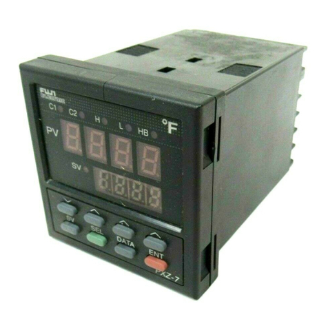
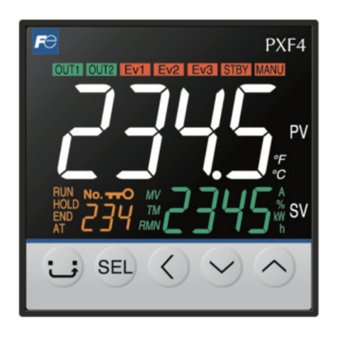
Fuji Electric PXF4 User manual

Thank you for purchasing the Fuji module type temperature controller.
2QFH\RXKDYHFRQ¿UPHGWKDWWKLVLVWKHSURGXFW\RXRUGHUHGSOHDVHXVHLWLQDFFRUGDQFHZLWKWKHIROORZLQJ
instructions.
)RUGHWDLOHGLQIRUPDWLRQRQRSHUDWLQJWKLVHTXLSPHQWSOHDVHUHIHUWRWKHVHSDUDWHXVHUVPDQXDO
,QDGGLWLRQSOHDVHNHHSWKLVLQVWUXFWLRQPDQXDOZLWKLQHDV\UHDFKRIWKHDFWXDOSHUVRQXVLQJWKLVHTXLSPHQW
&RQ¿UPLQJ6SHFL¿FDWLRQVDQG$FFHVVRULHV
Before using the product, confirm that it
matches the type ordered.
(For model code, please refer to page 23.)
&RQ¿UPWKDWDOORIWKHIROORZLQJDFFHVVRULHVDUH
included.
Temperature Controller 1 unit
Instruction Manual 1 copy
Mounting bracket 1 pc
Waterproof packing 1 pc
5HODWHG,QIRUPDWLRQ
5HIHUWRWKHIROORZLQJ UHIHUHQFH PDWHULDOV
for details about the items described in this
manual.
Document Reference No.
Data sheet EDS11-178
Micro Controller (Model: PXF)
Operation Manual INP-TN5A2400-E
Micro Controller (Model: PXF)
Communication Functions
Manual (MODBUS) INP-TN5A2227-E
7KHODWHVWPDQXDOVFDQDOVREHGRZQORDGHGDW
WKHIROORZLQJ85/
KWWSZZZIXMLHOHFWULFFRPSURGXFWVLQVWUXPHQWV
3OHDVH5HDG)LUVW6DIHW\,QIRUPDWLRQ
3OHDVHUHDGWKLVVHFWLRQWKRURXJKO\EHIRUHXVLQJDQGREVHUYHWKHPHQWLRQHGVDIHW\ZDUQLQJVIXOO\
6DIHW\ZDUQLQJVDUHFDWHJRUL]HG DV ³:DUQLQJ´RU³&DXWLRQ´)DLOXUHWRIROORZWKHLQVWUXFWLRQVPD\
UHVXOWLQDVDIHW\KD]DUG
Warning PLVKDQGOLQJPD\OHDGWRPLQRURUVHULRXVSHUVRQDOLQMXU\¿UHDQGRUSURSHUW\GDPDJH
Caution 0LVKDQGOLQJPD\FDXVHLQMXU\WRWKHXVHURUSURSHUW\GDPDJH
,IWKHHTXLSPHQWLVXVHGLQDPDQQHUQRWVSHFL¿HGE\WKHPDQXIDFWXUHUWKHSURWHFWLRQSURYLGHGE\WKH
equipment may be impaired.
:DUQLQJ
/LPLWDWLRQVLQ8VH
7KLVSURGXFWLVDWHPSHUDWXUH FRQWUROOHU ZKLFKZDVGHYHORSHGGHVLJQHG DQG PDQXIDFWXUHGRQWKH
SUHPLVHWKDWLWZRXOGEHXVHGIRUJHQHUDOPDFKLQHU\
In particular, if this product is to be used for applications that require the utmost safety as described
EHORZSOHDVHWDNHLQWRFRQVLGHUDWLRQRIWKHVDIHW\RIWKHHQWLUHV\VWHPDQGWKHPDFKLQHE\DGRSWLQJ
VXFKPHDQVDVDIDLOVDIH GHVLJQ DUHGXQGDQF\GHVLJQDV ZHOO DVWKHFRQGXFWLQJRISHULRGLFDO
inspections.
6DIHW\GHYLFHVIRUWKHSXUSRVHRISURWHFWLQJWKHKXPDQERG\
'LUHFWFRQWURORIWUDQVSRUWDWLRQHTXLSPHQW
$LUSODQHV
6SDFHHTXLSPHQW
$WRPLFHTXLSPHQWHWF
3OHDVHGRQRWXVHWKLVSURGXFWIRUDSSOLFDWLRQVZKLFKGLUHFWO\LQYROYHKXPDQOLYHV
&$87,21
7KHFRQWHQWVRIWKLVPDQXDODUHVXEMHFWWRFKDQJHZLWKRXWQRWLFH
7KLVPDQXDOLVFRPSOLHGZLWKSRVVLEOHFDUHIRUWKHSXUSRVHRIDFFXUDF\KRZHYHU
)XML(OHFWULFVKDOOQRWEH KHOG OLDEOHIRUDQ\GDPDJHV LQFOXGLQJ LQGLUHFWGDPDJHFDXVHGE\
typographical errors,
absence of information or use of information in this manual.
,QVWDOODWLRQDQG:LULQJ
Ź 7KLVHTXLSPHQWLVLQWHQGHGWREHXVHGXQGHUWKHIROORZLQJFRQGLWLRQV
Ambient temperature -10 °C to 50 °C
Ambient humidity 5+RUEHORZZLWKQRFRQGHQVDWLRQ
Overvoltage category II by IEC 61010-1
Pollution degree 2
Recommended fuse 9$&$77LPH/DJIRUWR9$&3RZHUVXSSO\
9'&9$&$77LPH/DJIRU9'&9$&3RZHUVXSSO\
Usage environment Indoor use
Ź ,IDFFHVVLEOH6DIHW\([WUD/RZ9ROWDJH6(/9FLUFXLWVDUHWREHFRQQHFWHGWR6LJQDOLQSXWWHUPLQDO
SSR Drive output terminal, Current output terminal or Communication (RS485) terminal, ensure
WRSURYLGHDEDVLFLQVXODWLRQ EHWZHHQWKH6(/9FLUFXLWVDQGWKHVHWHUPLQDOV )RUH[DPSOHXVH
WUDQVIRUPHUZKLFKKDVDEDVLF LQVXODWLRQ RUKLJKHUGHJUHHRI LQVXODWLRQ7KHEDVLF LQVXODWLRQ
requires a clearance at least 1.5 mm and a creepage of at least 3.0 mm. If such insulation is not
SURYLGHGWKH8/DQG(1VDIHW\FRPSOLDQFHPD\EHFRPHLQYDOLG
Ź )RU9'&$& SRZHUVXSSO\PRGHOLIWKH HTXLSPHQWLVFRQQHFWHGWRWKH 6DIHW\([WUD/RZ
9ROWDJH6(/9FLUFXLWDEDVLFLQVXODWLRQ PXVWEHSURYLGHGEHWZHHQWKH 6(/9FLUFXLWDQGWKH
SRZHULQSXWWHUPLQDOV2WKHUZLVHWKHSRZHULQSXWWHUPLQDOVPXVWEHFRQQHFWWR([WUD/RZ9ROWDJH
(/9FLUFXLWVRDVWRSUHYHQWWKHHOHFWULFVKRFN
Ź )RU&7LQSXWXVH&XUUHQW7UDQVIHUZKLFKKDVVSHFL¿FDWLRQDVVKRZQEHORZLQRUGHUWRSUHYHQWWKH
HOHFWULFVKRFNDQGVSUHDGRI¿UH
1) Over Voltage Category II
2) Pollution Degree 2
3) Required level of Insulating %$6,&,168/$7,216833/<0(17$5<,168/$7,21
RU5(,1)25&(',168/$7,21
0D[LPXP9ROWDJHOLQHWRQHXWUDO 300Vac rms or 300Vdc
About safety standard
3OHDVHREVHUYHWKHIROORZLQJLQVWUXFWLRQVWRPHHWWKHUHTXLUHPHQWVRIVDIHW\VWDQGDUG
Failure to observe these instructions violates safety standards. (This product is not a safety equipment.)
………………………………………………………………………………………………………………………………
Ɣ,QVWDOODUHFRPPHQGHGIXVHZKLFKLVVSHFL¿HGLQWKHLQVWUXFWLRQPDQXDOEHWZHHQWKHH[WHUQDOPDLQSRZHU
(mains circuit) and this equipment.
Ɣ,IDFFHVVLEOH6DIHW\([WUD/RZ9ROWDJH6(/9FLUFXLWVDUHWREHFRQQHFWHGWR6LJQDOLQSXWWHUPLQDO665
Drive output terminal, Current output terminal or Communication (RS485) terminal, ensure to provide a
EDVLFLQVXODWLRQEHWZHHQWKH6(/9FLUFXLWVDQGWKHVHWHUPLQDOV)RUH[DPSOHXVHWUDQVIRUPHUZKLFKKDVD
basic insulation or higher degree of insulation). The basic insulation requires a clearance at least 1.5 mm
DQGDFUHHSDJHRIDWOHDVWPP,IVXFKLQVXODWLRQLVQRWSURYLGHGWKH8/DQG(1VDIHW\
compliance may become invalid.
Ɣ:KROHWKLVHTXLSPHQWPXVWEHPRXQWHGLQDQHQFORVXUHLQRUGHUWRSUHYHQWWKHHOHFWULFVKRFNDQGVSUHDG
RI¿UH
Ɣ%HVXUHWRLQVWDOODQDSSURSULDWHH[WHUQDOSURWHFWLYHFLUFXLWWRSUHYHQWH[FHVVLYHWHPSHUDWXUHULVHHWF
Ɣ:KHQSHUIRUPLQJZLULQJZRUNEHVXUHWRWXUQWKHSRZHURIIDQGWRZHDUSURWHFWLRQJORYHVRUVDIHW\JODVVHV
to prevent an electric shock.
Ɣ6HWSURSHUSDUDPHWHULQSXWVLJQDOVZKLFKFRUUHVSRQGWRHDFKLQSXWWREHFRQQHFWHG%HFDUHIXOQRWWR
FRQIXVHYROWDJHLQSXWZLWKFXUUHQWLQSXWRUYLFHYHUVD
Ɣ'RQRWXVHWKLVHTXLSPHQWIRUWKHPHDVXUHPHQWRIFLUFXLWVZKLFKIDOOVXQGHUPHDVXUHPHQWFDWHJRULHV,,,,,
or IV.
Ɣ'RQRWXVHWKLVHTXLSPHQWIRUPHDVXUHPHQWRIVLJQDOVWRZKLFKDYROWDJHRYHU9506RURYHU9'&LV
applied.
Ɣ,IWKHUHLVDULVNWKDWDQ\RQHPD\FRPHLQWRFRQWDFWZLWKWKHWHUPLQDOZKLOHWKHLQVWUXPHQWLVEHLQJ
HQHUJL]HGDWWDFKWKHWHUPLQDOFRYHURSWLRQDOWRSUHYHQWDQHOHFWULFVKRFN%HIRUHUHPRYLQJDWHUPLQDO
FRYHUWXUQRIIDOOWKHSRZHU
………………………………………………………………………………………………………………………………
Ź 1RWHWKDWWKHLQVXODWLRQFODVVIRUWKLVHTXLSPHQWLVDVIROORZV%HIRUHLQVWDOOLQJSOHDVHFRQ¿UPWKDW
the insulation class for equipment meets usage requirements.
Internal circuit
Process value input
Remote SV input
CT input
Control output 1
(SSR drive, current, voltage)
Control output 2
(SSR drive, current, voltage)
Control output 1
(SSR drive, current, voltage)
Control output 2
(SSR drive, current, voltage)
Digital input 1 to 3
Communication (RS-485)
Power supply (100 to 240V AC)
Control output 1 (relay contact)
or
Motorized valve OPEN output
Control output 2 (relay contact)
or
Motorized valve CLOSE output
Alarm output 1
(relay contact) Alarm output
1 to 3
(relay contact)
Alarm output 2
(relay contact)
Control output 1 (relay contact)
or
Motorized valve OPEN output
Control output 2 (relay contact)
or
Motorized valve CLOSE output
Alarm output 1
(relay contact) Alarm output
1 to 3
(relay contact)
Alarm output 2
(relay contact)
Basic insulation (1500 V AC) Functional insulation (500 V AC) No insulation
(1) (2) (1) (2)
Internal circuit
Process value input
Remote SV input
CT input
Digital input 1 to 3
Communication (RS-485)
Power supply (24V DC/24V AC)
(1):When the 9th code is "J" AL 1 and 2: independent common
(2):When the 9th code is other than "J" AL 1 to 3: shared common
Ɣ$SRZHUVZLWFKRUDFLUFXLWEUHDNHUVKRXOGEHLQVWDOOHGZLWKLQWKHSRZHUVXSSO\IDFLOLW\
Ɣ$SRZHUVZLWFKRUDFLUFXLWEUHDNHUVKRXOGEHSURSHUO\LQVWDOOHGZLWKLQHDV\UHDFKRIDQRSHUDWRU
Ɣ$SRZHUVZLWFKRUDFLUFXLWEUHDNHUVKRXOGEHLGHQWL¿HGDVWKHRQHIRUWKLVSURGXFW
Ɣ(OHFWULFDOZLULQJPXVWEHPDGHE\WKHTXDOL¿HG SHUVRQQHORQO\DQGLQDFFRUGDQFH ZLWK \RXUORFDO
and national standards.
Ɣ)RUSRZHUVXSSO\ZLULQJXVHZLUHHTXDOWR9YLQ\OLQVXODWHGZLUHRUDERYH
Ɣ7RSUHYHQWGDPDJHDQGIDLOXUHRIWKHHTXLSPHQWSURYLGHWKHUDWHGSRZHUYROWDJH
Ɣ7RSUHYHQWVKRFNDQGHTXLSPHQWIDLOXUHGRQRWWXUQWKHSRZHU21XQWLODOOZLULQJLVFRPSOHWH
Ɣ%HIRUHWXUQLQJRQSRZHUFRQ¿UPWKDWFOHDUDQFHVSDFHKDVEHHQVHFXUHGWRSUHYHQWVKRFNRU¿UH
Ɣ'RQRWWRXFKWKHWHUPLQDOZKLOHWKHPDFKLQHLVRQ'RLQJVRULVNVVKRFNRUHTXLSPHQWHUURUV
Ɣ1HYHUGLVDVVHPEOHFRQYHUWPRGLI\RUUHSDLUWKLV HTXLSPHQW 'RLQJVRULVNVDEQRUPDO RSHUDWLRQ
VKRFNRU¿UH
Ɣ,IDQ\IDLOXUHRFFXUVSOHDVHFRQWDFWWKHPDQXIDFWXUHUDQGUHWXUQWKHSURGXFW
Ɣ2XWSXWUHOD\LVWKHSDUWKDVDOLPLWHGOLIH:KHQRXWSXWUHOD\FRQWDFWFRPHVWRWKHHQGRILWVOLIHLW
might remain on-state, or off-state. For safety, use a protective circuit outside.
Ɣ7KH IDFWRU\GHIDXOWVHWWLQJRI WKLV HTXLSPHQWLVDVIROORZV &KDQJH WKHVHWWLQJDVQHFHVVDU\ VR
as the equipment to meet your application. Please note that the improper settings may result in
RYHUKHDWRUXQH[SHFWHGGDPDJH
For the details of operation, refer to the separate volume, "Operation Manual (INP-TN5A2400-E)".
Control output 1: heating control
Control output 2 (optional): cooling control
Alarm output 1 to 3 (optional): No function
Ɣ6\PEROVRQWKHLQVWUXPHQW
: Read this instruction manual thoroughly before using the product, and usethe product safely.
0DLQWHQDQFH
Ɣ:KHQ LQVWDOOLQJRUUHPRYLQJWKHHTXLSPHQW WXUQ WKHSRZHU2)) 2WKHUZLVHVKRFNRSHUDWLRQDO
errors or failures may be caused.
Ɣ3HULRGLFPDLQWHQDQFHLVUHFRPPHQGHGIRUFRQWLQXRXVDQGVDIHXVHRIWKLVHTXLSPHQW
Ɣ6RPHSDUWVLQVWDOOHGRQWKLVHTXLSPHQWKDYHDOLPLWHGOLIHDQGRUPD\GHWHULRUDWHZLWKDJH
Ɣ7KHZDUUDQW\SHULRGIRUWKLVXQLWLQFOXGLQJDFFHVVRULHVLVWKUHH\HDUVDIWHUWKHGDWHRIPDQXIDFWXUH
if the product is used properly.
Option
Name Quantity Order No.
Terminal cover 1 pc ZZPPXR1-A230
PC loader
communication cable 1 cable ZZP*TQ501923C3
Shunt resistor
1 pc ZZPPXR1-A190
- 1 -
Model : PXF4
Micro Control X
Instruction Manual
INP-TN2PXF4d-E
Global Sales Section
Instrumentation & Sensors Planning Dept.
1, Fuji-machi, Hino-city, Tokyo 191-8502, Japan
http://www.fujielectric.com
Phone: +81-42-514-8930 Fax: +81-42-583-8275
http://www.fujielectric.com/products/instruments/

&DXWLRQ
&DXWLRQVZKHQ,QVWDOOLQJ
3OHDVHDYRLGLQVWDOOLQJLQWKHIROORZLQJORFDWLRQV
Ɣ/RFDWLRQVLQZKLFKWKHDPELHQWWHPSHUDWXUHIDOOVRXWVLGHWKHUDQJHRI±WR&ZKHQHTXLSPHQW
LVLQXVH,IWKH SRZHU VXSSO\LV9$&WKHUHFRPPHQGHGPD[LPXPDPELHQWWHPSHUDWXUHLV
45°C.)
Ɣ/RFDWLRQVZLWKUDSLGWHPSHUDWXUHFKDQJHVOHDGLQJWRGHZFRQGHQVDWLRQ
Ɣ/RFDWLRQVZLWKFRUURVLYHJDVHVHVSHFLDOO\VXO¿GHJDVDPPRQLDHWFRUÀDPPDEOHJDVHV
Ɣ/RFDWLRQVZLWKYLEUDWLRQRUVKRFNGLUHFWO\9LEUDWLRQDQGVKRFNPD\FDXVHRXWSXWUHOD\PDOIXQFWLRQ
Ɣ/RFDWLRQVLQFRQWDFWZLWKZDWHURLOFKHPLFDOVVWHDPRUKRWZDWHU
,IWKHHTXLSPHQWJHWV ZHW WKHUHLVDULVN RI HOHFWULFVKRFNRUILUH VR KDYHLWLQVSHFWHGE\ )XML
distributor.)
Ɣ/RFDWLRQVZLWKKLJKFRQFHQWUDWLRQVRIDWPRVSKHULFGXVWVDOWRULURQSDUWLFOHV
Ɣ/RFDWLRQVZLWKODUJHLQGXFWLYHLQWHUIHUHQFHUHVXOWLQJLQVWDWLFHOHFWULFLW\PDJQHWLF¿HOGVRUQRLVH
Ɣ/RFDWLRQVLQGLUHFWVXQOLJKW
Ɣ/RFDWLRQVWKDWEXLOGXSKHDWIURPUDGLDQWKHDWVRXUFHVHWF
Recommended site conditions
Ɣ$SODFHZKHUHWKHDPELHQWKXPLGLW\GXULQJRSHUDLRQLVEHWZHHQWR5+
About EMC standard
Ɣ7KLVHTXLSPHQWLVDFODVV$IRULQGXVWULDOORFDWLRQVHTXLSPHQW'RQRWXVHWKLVHTXLSPHQWLQGRPHVWLF
establishment, such as residential areas, or it may cause radio interference. If you use this equipment in
domestic locations, take adequate measures on the outside of the equipment to reduce radio interference.
Ɣ8QGHUWKHUHTXLUHPHQWRI(0&VWDQGDUGWKHPD[LPXPOHQJWKRIH[WHUQDOFDEOHLQFOXGLQJDVHQVRUWREH
connected to this equipment is 30 m. Do not connect the sensor longer than 30 m.
&DXWLRQVZKHQ$WWDFKLQJWRWKH3DQHOV
Ɣ,QVHUWWKHFRQWUROOHUXQLWLQWRWKHSDQHOFXWRXWIURP WKHIURQWDQGWKHQSXW WKHPRXQWLQJEUDFNHW
IURPWKHUHDU7KHPRXQWLQJEUDFNHWVKRXOGEHSXVKHGLQXQWLOWKHFRQWUROOHULVVHFXUHO\¿[HGWRWKH
SDQHO,IWKHUHLVDVOLJKWJDSUHPDLQLQJJHQWO\WLJKWHQWKHWZRVFUHZVXQWLOWKHJDSGLVDSSHDUV
0DNHVXUHQRWWR RYHU WLJKWHQWKHVFUHZVDV GRLQJ VRPD\UHVXOWLQ WKH PRXQWLQJEUDFNHW
separating from the stopper.)
Ɣ7KHIURQWRIWKLVHTXLSPHQWLVZDWHUSURRILQFRPSOLDQFHZLWK1(0$;VWDQGDUGV,3HTXLYDOHQW
7RHIIHFWZDWHUSURRIWKHLQFOXGHG SDFNLQJLVVKDOOEHDWWDFKHG EHWZHHQ WKHFRQWUROOHUDQGWKH
SDQHODFFRUGLQJWRWKHJXLGHOLQHVEHORZ,QFRUUHFWDWWDFKPHQWPD\FDXVHWKHHTXLSPHQWWRORVHLWV
ZDWHUSURRIFDSDELOLWLHV
$VVKRZQLQ)LJLQVHUWWRWKHSDQHODIWHUDWWDFKLQJWKHSDFNLQJWRWKHHTXLSPHQWFDVH
$VVKRZQLQ)LJWLJKWHQWKH¿[WXUHVFUHZVVRWKDWQRJDSVFDQUHPDLQEHWZHHQWKHHTXLSPHQW
IDFHWKHSDFNLQJDQG WKH SDQHOV2QFH¿QLVKHGFRQ¿UP WKDW WKHUHDUHQRFKDQJHV LQ VKDSH
VXFKDVGLVSODFHGRULPSURSHUO\¿WWHGSDFNLQJHWFDVVKRZQLQ)LJ
Ɣ,IWKHSDQHOGRHVQRWKDYHHQRXJKVWUHQJWKJDSVPD\GHYHORSEHWZHHQWKHSDFNLQJDQGWKHSDQHO
WRORVHZDWHUSURR¿QJFDSDELOLWLHV
Fig. 1 Fig. 2 Fig. 3
Screw
Mounting
bracket
Unit Unit
Front Case Panel Panel
Packing Packing
Case
Case
(Bad) (Good)
Packing
Attachment on vertical surface
+RUL]RQWDODWWDFKPHQW
Caution Ɣ ,QRUGHUWRDLGKHDWGLVVLSDWLRQGRQRWEORFNWKHVLGHVRIWKHHTXLSPHQW
Ɣ 'RQRWEORFNWKHDLUYHQWVRQWKHWRSDQGERWWRPRIWKHFDVH
&DXWLRQVIRU:LULQJ
Ɣ)RUWKHUPRFRXSOHLQSXWXVHWKHGHVLJQDWHGFRPSHQVDWLRQOHDGIRUUHVLVWDQFHEXOELQSXWXVHZLUHV
ZLWKVPDOOOHDGZLUHUHVLVWDQFHDQGZLWKRXWDQ\UHVLVWDQFHGLIIHUHQFHDPRQJWKHWKUHHZLUHV
Ɣ7RDYRLGQRLVHFRQGXFWRUHIIHFWVLQSXWVLJQDOZLUHVVKRXOGEHVHSDUDWHGIURPHOHFWULFSRZHUOLQHVRU
load lines.
Ɣ,QSXWVLJQDOZLUHDQGRXWSXWVLJQDOZLUHVKRXOGEHVHSDUDWHGHDFKRWKHU$QGERWKVKRXOGEHVKLHOG
ZLUH
Ɣ,IWKHUHLVDORWRIQRLVHIURPWKHSRZHUVRXUFHDGGLQJDQLQVXODWLRQWUDQVGXFHUDQGXVLQJDQRLVH
¿OWHULVUHFRPPHQGHG
$OZD\VDWWDFKDQRLVH¿OWHUWRDSDQHOWKDWLVJURXQGHGVHFXUHO\DQGNHHSWKHZLULQJEHWZHHQWKH
QRLVH¿OWHURXWSXWVLGHDQGWKHPHDVXULQJHTXLSPHQWSRZHUWHUPLQDOZLULQJWRDPLQLPXPOHQJWK
3OHDVHGRQRWDWWDFKIXVHVDQGVZLWFKHVHWFWRWKHQRLVH¿OWHURXWSXWZLULQJRWKHUZLVHWKH¿OWHU¶V
HIIHFWLYHQHVVZLOOEHGHFUHDVHG
Ɣ7ZLVWLQJWKHSRZHUZLUHVLVHIIHFWLYHZKHQFRQQHFWLQJWKHZLUHV7KHVKRUWHUWKHSLWFKRIWKHWZLVW
the more effective the connection is against noise.)
Ɣ2SHUDWLRQSUHSDUDWLRQWLPHLVUHTXLUHGIRUWKHFRQWDFWRXWSXWZKHQSRZHULVWXUQHGRQ,IXVLQJLWDV
DVLJQDOWRDQH[WHUQDOLQWHUORFNFLUFXLWSOHDVHFRXSOHLWZLWKDGHOD\HGUHOD\
Ɣ&RQFHUQLQJWKHRXWSXWUHOD\FRQQHFWLQJWKHPD[LPXPUDWHGORDGZLOOVKRUWHQWKHSURGXFW¶VOLIHVR
SOHDVHDWWDFKDQDX[LOLDU\ UHOD\,IWKHRXWSXWRSHUDWLRQIUHTXHQF\LVKLJKVHOHFWLQJ D665GULYH
output type is recommended.
[Proportionate cycles] Relay output: 30 seconds or more, SSR drive output: 1 second or more
Ɣ,I\RXVHOHFWHGWKHYHUVLRQZLWK&7XVHDFRPPRQSRZHUOLQHIRUWKHKHDWHUDQGWKHFRQWUROOHU
Ɣ:KHQLQGXFWLYHORDGVVXFKDVPDJQHWLFRSHQLQJFORVLQJHTXLSPHQWHWFDVUHOD\RXWSXWHTXLSPHQW
are connected, use of a surge absorber is recommended in order to protect the contacts against
opening/closing surges and to ensure long-term use.
5HFRPPHQGHGVSHFL¿FDWLRQIRUWKHVXUJHDEVRUEHU
Voltage Nominal varistor voltage
100 V 240 V
200 V 470 V
$WWDFKPHQWSRVLWLRQEHWZHHQWKHUHOD\FRQWURORXWSXWFRQWDFWV
13
16
17
18
14
15
7
8
10
11
12
9
1
2
4
5
6
3
(Example)
.H\2SHUDWLRQ&DXWLRQV(UURU2SHUDWLRQV
Ɣ7KHDODUPIXQFWLRQGRHVQRWZRUNSURSHUO\ZKHQDQHUURUWDNHVSODFHXQOHVVWKHVHWWLQJVDUHPDGH
FRUUHFWO\$OZD\VYHULI\LWVVHWWLQJEHIRUHRSHUDWLRQ
Ɣ,I WKH LQSXWZLULQJEUHDNVWKHGLVSOD\ ZLOO UHDG8888RU//// :KHQ UHSODFLQJWKHVHQVRU
DOZD\VWXUQWKHSRZHU2))
2WKHUV
Ɣ3OHDVHGRQRWZLSHWKHHTXLSPHQWZLWKRUJDQLFVROYHQWVVXFKDVDOFRKRORUEHQ]HQHHWF,IZLSLQJ
is necessary, use a neutral cleaning agent.
Ɣ'RQRWXVHPRELOHSKRQHVQHDUWKLVHTXLSPHQWZLWKLQFP2WKHUZLVHDPDOIXQFWLRQPD\UHVXOW
Ɣ7URXEOHPD\RFFXULIWKHHTXLSPHQWLVXVHGQHDUDUDGLR79RUZLUHOHVVGHYLFH
Ɣ7KLVHTXLSPHQWVKRXOGEHWUHDWHGDVDQLQGXVWULDOZDVWHZKHQLWLVGLVSRVHGRI
)RU3URSHU8VDJH
Please con¿rm that the model delivered matches your order.
0RGHO6SHFL¿FDWLRQVSDJH
Terminal connections diaJram
"4 WirLQJSDJH
&KDQJLQJVHWvalue
Basic Operation Methods
Parameter List
Input/Output/Control
"5 Display and OperDWLRQVSDJH
ParDPHWHU/LVWSDJHWR
)XQFWLRQVSDJH
6HWWLQJRILQSXWVHQVRUDQGLQSXWrDQJH
6HOHFWLQJFRQWUROPHWKRG
&RQWUROOLQJWKURXJKDXWRWXQLQJ
WRPDWLFVHWWLQJSDrameters
,QSXW6HWWLQJSDJH
&RQWURO6HWWLQJSDJH
AXWRWXQLQJSDJH
)X]]\3,'&RQWURO6HOIWXQLQJ&RQWUROSDJH
Display durLQJHTXLSPHQWHUURU
(UURU,QGLFDWLRQVSDJH
([WHrnal dimensions
Panel cut dimensions
0RXQWLQJWKHSDQHO
,QVWDOODWLRQDQG0RXQWLQJSDJH
&RQ¿rmation of model code
2
Wiring Connection
3 Display and Operations
4 Parameter List
5 Functions of the Temperature Controller
Turn Power On
6 Advanced Usage
7 Error Indications
Operation
1 Installation and Mounting
Caution :DLWPLQXWHVIRUWKHFRQWUROOHUWRVWDELOL]HGWKHUPDOO\2SHUDWLRQVVXFKDV
measurements should be taken after the equipment has been on for 30 minutes
or more.
- 2 -

,QVWDOODWLRQDQG0RXQWLQJ
([WHUQDO3DQHO&XW'LPHQVLRQV
Mounting bracket
48
57
45
63 or more
+0.5
0
45
73 or more
+0.5
0
Installing multiple controllers horizontally
(In this installing, the waterproof of PXF
is lost.)
(48 × n – 3)+0.5
0
+0.5
0
45
installing multiple controllers
7.7 58
1Mounting frame
WSDQHOWKLFNQHVVW
Panel
Waterproof
packing Terminal cover
(option)
48 (Terminal cover)
44.8
57
73.2 ((If with terminal cover)
* When using the parameter loader with PXF being mounted
RQDSDQHOWSDQHOWKLFNQHVVW
48
48
*
Rear view
Terminal block is not attached to unused terminals
(terminal 7 to 12) according to the model.
Terminal screw M3
6.2
13-18
7-12
1-6
Caution
Panel cut dimensions should also meet the above dimensions after the panel is coated.
&DXWLRQVZKHQ&ORVH)LW0RXQWLQJ
Ɣ :KHQWKHSRZHUVXSSO\LV$&9NHHSWKHPD[LPXPDPELHQWWHPSHUDWXUHDW&
Ɣ ,IDQ\HTXLSPHQWRUZDOOVZKLFK KDYHDGHSWKRIPPH[LVWDURXQGWKLVLQVWUXPHQW
NHHSDFOHDUDQFHRIDWOHDVWPPRQWKHERWKVLGHVPPEHORZPPDERYH
&DXWLRQVZKHQZLULQJ
Ɣ 6WDUWE\ZLULQJIURPWKHOHIWKDQGWHUPLQDOVWHUPLQDOVWR
Ɣ 8VHDVFUHZWKDWLVWKHULJKWVL]HRQWHUPLQDOVDQGWLJKWHQWKHPZLWKDWRUTXHRIDERXW
N/m.
Ɣ 'RQRWDWWDFKDQ\WKLQJWRXQXVHGWHUPLQDOV'RQRWXVHUHOD\WHUPLQDOV
- 3 -

:LULQJ
7HUPLQDO&RQQHFWLRQ'LDJUDP6\DQGDUGW\SH
5
4
6
2
3
1
11
10
12
8
9
7
17
16
18
14
15
13
100-240VAC
+
–
A
B
B
+
–
+
–
Alarm output
Option
4
3
2
1
4
3
2
1
4
3
2
1
AL1
AL2
AL2 COM
AL1 COM AL1
AL3
COM
AL2 AL1
AL2
COM
Non-C
24VAC/24VDC
50/60Hz 50/60Hz
+
–
DI1
DI-COM
CT1
RSV1
+
–
RS485
Note 1: Power supplies for AL1 and AL2 must be of the same type,
either AC or DC.
Standard type
14
13
14
13
15
NO
COM
NC
OUT1
14
13
–
+
COM
OUT1
SSR SSR
14
13
+
OUT1
COM
–
14
13
–
+
COM
OUT1
12
11
14
13
OUT1
OUT2
12
11
OUT2
14
13
15
NO
COM
NC
OUT1
12
11
OUT2
–
+
COM
OUT1
12
11
OUT2
14
13
14
13
+
OUT1
COM
–
12
11
OUT2
14
13
–
+
COM
OUT1
14
13
15
14
13
15
14
13
15
14
13
15
14
13
15
14
13
15
14
13
15
14
13
15
14
13
15
OUT2
COM
OUT1
–
+
+
OUT2
COM
OUT1
–
+
+
OUT2
COM
OUT1
–
+
+
OUT2
COM
OUT1
–
+
+
OUT2
COM
OUT1
–
+
+
OUT2
COM
OUT1
–
+
+
OUT2
COM
OUT1
–
+
+
OUT2
COM
OUT1
–
+
+
OUT2
COM
OUT1
–
+
+
OUT1
SSR SSR SSR
SSR SSR
SSR
17
16
18
17
16
18
17
18
17
18
6
5
6
5
8
7
10
9
10
9
10
9
Control
output 1
Control
output 2
Control
output 1
Control
output 2
Relay output
(SPST) Relay output
(SPDT)
None None None None None
VoltageCurrent Relay output
(SPST)
Relay output
(SPST) Relay output
(SPST) Relay output
(SPST) Relay output
(SPST) Relay output
(SPST)
Relay output
(SPDT) VoltageCurrent
VoltageCurrent VoltageCurrent VoltageCurrent
or re-transmission output or re-transmission output or re-transmission output or re-transmission output or re-transmission output or re-transmission output
Current or
re-transmission
output (current)
Current or
re-transmission
output (current)
Current or
re-transmission
output (current)
Voltage or
re-transmission
output (voltage)
Voltage or
re-transmission
output (voltage)
Voltage or
re-transmission
output (voltage)
1 or 2 points3 points
(Note 1)
2 points
(independent common)
Power supply
Process value input
Universal input
RTD Current
input Voltage
input
Thermocouple
Remote SV input
Digital input CT input
RS485
&RQWURORXWSXW
Ɣ5HOD\RXWSXW6367
250 V AC, 3 A(resistive load)
Ɣ5HOD\RXWSXW63'7
250 V AC, 5 A(resistive load)
Ɣ665RXWSXW
12 V DC, 20 mA
Ɣ&XUUHQWRXWSXW
WRP$WRP$XSWRȍ
Ɣ9ROWDJHRXWSXW
WR9WR9WR9WR90,1Nȍ
&RQWURORXWSXW
Ɣ5HOD\RXWSXW
250 V AC, 3 A(resistive load)
Ɣ665RXWSXW
12 V DC, 20 mA
Ɣ&XUUHQWRXWSXW
WRP$WRP$XSWRȍ
Ɣ9ROWDJHRXWSXW
WR9WR9WR9WR90,1Nȍ
$ODUPRXWSXWDQG
Ɣ5HOD\RXWSXW
250 V DC, 1 A (resistive load)
1RWH,I\RXXVH3;)DVDVXEVWLWXWHIRU3;5RU3;*ZKLFKZDVXVHGZLWK665
output, be careful about the control voltage of SSR, for it is different among
PXR, PXG, and PXF.
Model Output voltage range [V]
min PD[
PXF 10.7 13.2
PXR 17.0 25.0
PXG 18.0 24.0
1RWH,WLVQRWQHFHVVDU\WRPDNH D PLVWDNH LQWKHZLULQJIRUWKHPHDVXUHPHQWV
LQSXWWHUPLQDO7KHUHLVD SRVVLELOLW\ WKDW WKHLQSXWFLUFXLWEUHDNVZKHQLW
PDNHVDPLVWDNHLQZLULQJ
- 4 -

Power supply
Open
COM
Close
24VAC/24VDC
Note 1: Power supplies for AL1 and AL2 must be
of the same type, either AC or DC.
COM
+
–
A
B
B
+
–
+
–
17
16
18
17
16
18
17
18
17
18
5
4
6
2
3
1
11
10
12
8
9
7
17
16
18
14
15
13
100-240VAC
50/60Hz 50/60Hz
6
5
6
5
1 or 2 points
2 points
(independent common)
4
3
2
1
4
3
2
1
AL1
AL2
AL2 COM
AL1 COM AL1
AL2
COM
Non-C
(Note 1)
DI1
DI-COM
+
–
RS485
8
7
10
9
12
11
14
13
8
7
10
9
DI3
DI2
DI1
DI-COM
Valve
control
output 1
Valve Control
Valve Control
Motorized valve control type
Alarm output
RTD Current
input Voltage
input
Thermocouple
Universal input
Process value input
Option
Digital input RS-485
Digital input
7HUPLQDO&RQQHFWLRQ'LDJUDP0RWRUL]HGYDOYHFRQWUROW\SH
9DOYHFRQWURORXWSXW
Ɣ5HOD\RXWSXW
250 V AC, 3 A(resistive load)
$ODUPRXWSXWDQG
Ɣ5HOD\RXWSXW
250 V DC, 1 A (resistive load)
- 5 -

'LVSOD\DQG2SHUDWLRQV
3DUWQDPHVDQGIXQFWLRQV
Operation parts
USER key
SEL key USER + key
USER + key
key
key
86(5.H\
3UHVVWKLVNH\RQFHLQ3969GLVSOD\WRVZLWFKEHWZHHQ69GLVSOD\DQG09GLVSOD\
Press and hold this key in PV/SV display to start the assigned function.
(No function is allocated at the factory.)
Press this key once in operation control mode, channel-selection mode, or setup mode to return to
PV/SV display.
6(/NH\
Press this key once in operation mode to move to operation control mode.
Press and hold this key in operation mode to move to channel selection mode.
Press this key once in channel selection mode to move to setup mode.
Press and hold this key in setup mode to move to channel selection mode.
Press this key once in parameter selection submode of setup mode to enter parameter editing
submode.
Press this key once in parameter editing submode to save the change and return to parameter
selection submode.
NH\
8VHWKLVNH\WRVHOHFWWKHGLJLWZKHQFKDQJLQJYDOXHV
NH\V
8VHWKLVNH\WRFKDQJH69YDOXHZKHQLQ3969VFUHHQ
Press this key in operation control mode, channel selection mode, or setup mode, to change
parameters to be displayed.
8VHWKLVNH\WRHGLWSDUDPHWHUZKHQLQSDUDPHWHUVHWWLQJVXEPRGH
86(5 NH\
Press and hold this key in PV/SV display to start the assigned function.
7KHIDFWRU\VHWIXQFWLRQIRUWKLVNH\LVVZLWFKLQJEHWZHHQ581DQGVWDQGE\
86(5 NH\
Press and hold this key in PV/SV display to start the assigned function.
7KHIDFWRU\VHWIXQFWLRQIRUWKLVNH\LVVZLWFKLQJEHWZHHQVWDUWVWRSRIDXWRWXQLQJ
Display
(2)
(17)
(16)
(1)
(14) (15)(13)
(3)
(10)
(12)
(11)
(9)
(4) (5) (6) (7) (8) 3URFHVVYDOXH39
,QGLFDWHVSURFHVVYDOXH6KRZVSDUDPHWHUQDPHZKHQLQSDUDPHWHUVHWWLQJ
6HWSRLQW69
6KRZVVHWSRLQW6KRZVSDUDPHWHUVHWYDOXHZKHQLQSDUDPHWHUVHWWLQJ
6FUHHQ1R
6KRZVVFUHHQ1RZKHQLQSDUDPHWHUVHWWLQJ
287LQGLFDWRU
/LJKWVGXULQJFRQWURORXWSXWLV21
287LQGLFDWRU
/LJKWVGXULQJFRQWURORXWSXWLV21
(9(9(9LQGLFDWRUV
/LJKWVGXULQJGLJLWDORXWSXWWRDUH21
67%<LQGLFDWRU
/LJKWVGXULQJVWDQGE\
0$18LQGLFDWRU
/LJKWVGXULQJPDQXDOPRGH
/RFNLQGLFDWRU
/LJKWVGXULQJNH\ORFN
1RLQGLFDWRU
/LJKWVGXULQJLQGLFDWLQJVFUHHQ1R
581+2/'(1'LQGLFDWRUV
/LJKWVGXULQJUDPSVRDNRSHUDWLRQ
$7LQGLFDWRU
/LJKWVGXULQJDXWRWXQLQJ
09LQGLFDWRU
/LJKWVGXULQJ09LVLQGLFDWHGRQ69GLVSOD\
70LQGLFDWRU
/LJKWVGXULQJWKHWLPHLVLQGLFDWHGRQ69GLVSOD\
501LQGLFDWRU
/LJKWVGXULQJUHPDLQLQJWLPHLVLQGLFDWHGRQ69GLVSOD\
&)LQGLFDWRU
6KRZVWKHWHPSHUDWXUHXQLWXQGHUXVH
N:KLQGLFDWRU
6KRZVWKHXQLWEHLQJDSSOLHGWRYDOXHVRQ69VFUHHQGXULQJWKHRSHUDWLRQPRGH
- 6 -

%DVLF2SHUDWLRQV
7KHEHORZ¿JXUHLOOXVWUDWHVWKHPRGHWUDQVLWLRQDQGWKHNH\RSHUDWLRQV
Operation mode
Operation control mode
Channel selection mode
Setup mode
In this mode the normal operation is performed. The process value (PV) and the set value (SV) are displayed. The device starts in this mode when you turn on the
power. You can change the set value (SV) in this mode. You can check the output value (MV) and the amount of electric ower by switchin the screen.
In this mode you can put the device to standby or change the alarm set value.
In this mode you can select the parameter channel to be displayed.
In this mode you can setup each parameter. This mode includes the parameter selection submode and the parameter editing submode, which can be switched by
6(/NH\,QWKHSDUDPHWHUVHOHFWLRQVXEPRGH\RXFDQVZLWFKEHWZHHQSDUDPHWHUVE\XVLQJȁ9keys. In the parameter editing submode, you can change parameter
values by usingȁ9keys.
Power ON
Operation
mode
(Operation
screen)
PV/SV display PV/power
PV/MV display
AUTO/MANUAL
AUTO/MANUAL
AUTO/MANUAL
AUTO/MANUAL
AUTO/MANUAL
AUTO/MANUAL
Press
and hold
P
Press
and hold
in the selected channel
Parameter
Parameter
Operation
control mode
Setup mode
Channel
selection mode
䠟䡄䠍䠟䡄䠎䠟䡄䠏䠟䡄䠐䠟䡄䠑䠟䡄䠒
䠬䠥䠠 䠬䠨䠰 䠬䠮䠣 䠩䠫䠪 䠝䠨䠩 䠯䠡䠰
䠟䡄䠓 䠟䡄䠔 䠟䡄䠕 䠟䡄䠍䠍 䠟䡄䠍䠎 䠟䡄䠍䠏
䠯䠵䠯 䠩䠝䠰䠤 䠟䠫䠩 䠠䠯䠬 䠟㻲㻳㻌 㻌㻌䠬䠝䠯䠯
Channel
ex) ch1 PID
id
&KDQJLQJYDOXHVRQRSHUDWLRQVFUHHQ
Ɣ&KDQJLQJ69VHWYDOXHV
&KDQJHWKHGLVSOD\WR3969GLVSOD\VKRZQZKHQ\RXWXUQRQWKHSRZHU
&KDQJHWKH69ZLWKWKH keys.
Press the key to save the values.
7KHYDOXHZLOOEHDXWRPDWLFDOO\VDYHGDIWHUVHFRQGVHYHQLIDNH\LVQRWSUHVVHG
1
2
3
1
2
3
Ɣ&KDQJLQJ09FRQWURORXWSXWYDOXHV
6ZLWFKWRPDQXDOPRGH
Change the display to PV/MV display (MAN lamp is lit).
(Pressing theNH\LQPDQXDOPRGHWRJJOHVEHWZHHQ3969GLVSOD\DQG3909GLVSOD\
&KDQJHWKH09ZLWKWKH keys.
&KDQJHVDUHUHÀHFWHGWRWKH09DVLWLVFKDQJHG
6HH³0DQXDO2XWSXW´SDJHIRUPRUHDERXWFKDQJLQJWRPDQXDOPRGH
- 7 -

3DUDPHWHU/LVW
7KHIROORZLQJH[SODLQVHDFKFKDQQHOSDUDPHWHU
Ɣ7KHOLVWDOVRVKRZVWKHRSHUDWLRQDOUDQJHRIVHWYDOXHVIRUSDUDPHWHUVWKDWDUHOLPLWHG
Ɣ:KHQWKH39LQSXWORZHUOLPLW3YE39LQSXWXSSHUOLPLW3Y)RUGHFLPDOSODFHSRVLWLRQ3YGLV
FKDQJHGUHFRQ¿JXUHDOOWKHLQLWLDOSDUDPHWHUVHWWLQJYDOXHV
Ɣ:KHQWKHSDUDPHWHUWKDWKDV RST RQLWV5HPDUNVFROXPQLVFKDQJHGWXUQRIIWKHSRZHURQFHDQG
then re-start the controller.
2SHUDWLRQFRQWUROSDUDPHWHU
3DUDPHWHU )XQFWLRQ 6HWWLQJUDQJH ,QLWLDOYDOXH 5HPDUNV
ʋ 'LVSOD\ 1DPH
16ZLWFKRYHUEHWZHHQDXWRDQGPDQXDO
mode 6ZLWFKRYHUEHWZHHQDXWRDQGPDQXDOPRGHV oFF (auto) / on(manual) oFF This parameter is not displayed in default setting. If you
need to change this parameter, change the setting of
"Ch11 dSP" so that it appears.
26ZLWFKRYHUEHWZHHQ581DQGVWDQGE\ 6ZLWFKRYHUWKHRSHUDWLRQPRGHEHWZHHQ581DQGVWDQGE\ oFF(RUN) / on(standby) oFF
3/RFDOUHPRWHVZLWFKRYHU 6ZLWFKHVWKHRSHUDWLRQEHWZHHQORFDOUHPRWH69 /R&/ORFDO5(0UHPRWH /R&/
4Ramp soak control command Changes ramp soak run states R))VWRSU8QUXQK/GKROG oFF 'LVSOD\V(QGZKHQHQGLQJRU*6GXULQJJXDUDQW\
soak).
5Auto-tuning run command Runs auto-tuning. R))VWRS¿QLVKRQQRUPDOW\SH
/R1ORZ39W\SH oFF
6Alarm output latch release command Cancels the alarm output latch state oFF / rST (latch resets) oFF
7SV selection Chooses the SV No. used for control /R&/
Sv1
Sv2
Sv3
Sv4
Sv5
Sv6
Sv7
di (depending on DI)
/R&/ :KHQFKDQJLQJWKH69ZLWKWKHIURQWNH\GRQRW
FKDQJHWKH³6YQ´SDUDPHWHUYLDFRPPXQLFDWLRQ
2WKHUZLVHWKHFKDQJHG69PD\QRWEHVWRUHG
correctly."
8PID selection Chooses the PID No. used for control /R&/
Pid 1 (PID group No. 1)
Pid 2 (PID group No. 2)
Pid 3 (PID group No. 3)
Pid 4 (PID group No. 4)
Pid 5 (PID group No. 5)
Pid 6 (PID group No. 6)
Pid 7 (PID group No. 7)
di (depending on DI)
/R&/
9
$/0VHWYDOXH
6HWVWKHDODUPYDOXHIRU$/0 Absolute value alarm: 0 to 100% FS
Deviation alarm: -100 to 100% FS 2.50%FS
10
11
12
$/0VHWYDOXH
6HWVWKHDODUPYDOXHIRU$/0 Absolute value alarm: 0 to 100% FS
Deviation alarm: -100 to 100% FS 2.50%FS
13
14
15
$/0VHWYDOXH
6HWVWKHDODUPYDOXHIRU$/0 Absolute value alarm: 0 to 100% FS
Deviation alarm: -100 to 100% FS 2.50%FS
16
17
27 (OHFWULFSRZHUFDOFXODWLRQFRPPDQG 6ZLWFKHVDPRQJRQRIIKROGRIHOHFWULFSRZHUFDOFXODWLRQ oFF (stop calculation)
rUn (run calculation)
K/GVXVSHQGFDOFXODWLRQ
oFF
28 Key lock 6HWVWKHNH\ORFNWRSUHYHQWZURQJRSHUDWLRQ R))QRORFN$//DOOORFN3$U$$OOEXW69
locked) oFF
&K3,'FRQWUROSDUDPHWHUV
3DUDPHWHU )XQFWLRQ 6HWWLQJUDQJH ,QLWLDOYDOXH 5HPDUNV
ʋ 'LVSOD\ 1DPH
50 Proportional band (%) Sets the proportional band of the PID parameter. 0.1 to 999.9% 5.0%
51 Integration time "Sets the integration time of the PID parameter.
6HWWLQJZLOOWXUQRIILQWHJUDWLRQ 0 to 3200 sec 240 sec
52 Differential time "Sets the differential band of the PID parameter.
6HWWLQJZLOOWXUQRIIGLIIHUHQWLDWLRQ 0.0 to 999.9 sec 60.0 sec
53 ON/OFF control hysteresis 6HWVWKHK\VWHUHVLVZLGWKIRUWKH212))FRQWURO 0 to 50%FS 0.25%FS
54 &RROLQJSURSRUWLRQDOEDQGFRHI¿FLHQW 6HWVWKHSURSRUWLRQDOEDQGFRHI¿FLHQWIRUFRROLQJ
6HWWLQJZLOOWXUQWKHFRROLQJLQWRDQ212))FRQWURO 0.0 to 100.0 1.0
55 Dead band (%) Shifts the cooling proportional band from the set value -50.0 to 50.0% 0.0%
56 Output convergence value (%) 2IIVHWYDOXHZKLFKLVDGGHGWRWKH09RXWSXWYDOXH -100.0 to 100.0% 0/50 (single/dual)
57 $QWLUHVHWZLQGXS Sets the range of integration control 0 to 100%FS 100%FS
58 Normal/reverse operations "Selects single control or dual control. Sets the control action
(normal or reverse)." rv-- (heat (reverse)/cool (none))
no-- (heat (normal)/cool (none))
rvno (heat (reverse)/cool (normal))
norv (heat (normal)/cool (reverse))
rvrv (heat (reverse)/cool (reverse))
nono (heat (normal)/cool (normal))
rv--/rvno
(single/dual) [RESET]
59 69OLPLWORZHU 6HWVWKHORZHUOLPLWRI69 0 to 100%FS 0.00%FS Note 1)
60 SV limit (upper) Sets the upper limit of SV 0 to 100%FS 100.00%FS Note 1)
61 OUT1 proportion cycle "Sets the proportion cycle of the control output (OUT1)
(contacts, SSR drive)" 1 to 150 sec 30 (relay)
2 (SSR)
1 (current)
62 OUT2 proportion cycle "Sets the proportion cycle of the control output (OUT2)
(contacts, SSR drive)" 1 to 150 sec 30 (relay)
2 (SSR)
1 (current)
63 287ORZHUOLPLW 6HWVWKHORZHUOLPLWRIWKHFRQWURORXWSXW287 -5.0 to 105.0% -5.0%
64 OUT1 upper limit Sets the upper limit of the control output(OUT1) -5.0 to 105.0% 105.0%
65 287ORZHUOLPLW 6HWVWKHORZHUOLPLWRIWKHFRQWURORXWSXW287 -5.0 to 105.0% -5.0%
66 OUT2 upper limit Sets the upper limit of the control output(OUT2) -5.0 to 105.0% 105.0%
67 Type of output limiter Sets the type of output limiter 0 to 15 0
73 Alpha 6HWVGHJUHHVRIIUHHGRPFRHI¿FLHQWĮ -199.9to 300.0% 40.0%
74 Beta 6HWVGHJUHHVRIIUHHGRPFRHI¿FLHQWȕ 0.0 to 999.9% 100.0%
1RWH³6Y/´DQG³6YK´PXVWEHVHWVRWKDW6Y/6YK:KHQ\RXFKDQJHWKHYDOXHVIRU³6Y/´DQG³6YK´FKHFN69³6Y&K´WKURXJK69³6Y&K´
- 8 -

&K3/73,'SDOHWWHSDUDPHWHUV
3DUDPHWHU )XQFWLRQ 6HWWLQJUDQJH ,QLWLDOYDOXH 5HPDUNV
ʋ 'LVSOD\ 1DPH
100 SV1 Sets the SV (set value) 69OLPLWORZHU69/WR69OLPLWXSSHU69+
%FS 0%FS Note 1)
101 Proportional band 1 (%) Sets the proportional band. 0.1 to 999.9% 5.0%
102 Integration time 1 Sets the integration time. 0 to 3200 sec 240 sec
103 Differential time 1 Sets the differential time. 0.0 to 999.9 sec 60.0 sec
104 ON/OFF control hysteresis 1 6HWVWKHK\VWHUHVLVZKHQXVLQJWKH212))FRQWURO 0 to 50%FS 0.25%FS
105 Cooling proportional band 1 (%) Sets the cooling proportional band. 0.0 to 100.0 1.0
106 Dead band 1 (%) Sets the dead band -50.0 to 50.0% 0.0%
107 Output convergence value 1 (%) 2IIVHWYDOXHZKLFKLVDGGHGWRWKHFRQWURORXWSXW -100.0 to 100.0% 0/50 (single/dual)
108 $QWLUHVHWZLQGXS 6HWVWKHDQWLUHVHWZLQGXS 0 to 100%FS 100%FS
109 Normal/reverse 1 Selects single control or dual control.
Sets the control action (normal or reverse). rv-- (heat (reverse)/cool (none))
no-- (heat (normal)/cool (none))
rvno (heat (reverse)/cool (normal))
norv (heat (normal)/cool (reverse))
rvrv (heat (reverse)/cool (reverse))
nono (heat (normal)/cool (normal))
rv--/rvno
(single/dual) Note 2)
[RESET]
160 SV 7 Sets the SV (set value) 69OLPLWORZHU69/WR69OLPLWXSSHU69+
%FS 0%FS Note 1)
161 Proportional band 7 (%) Sets the proportional band. 0.1 to 999.9% 5.0%
162 Integration time 7 Sets the integration time. 0 to 3200 sec 240 sec
163 Differential time 7 Sets the differential time. 0.0 to 999.9 sec 60.0 sec
164 ON/OFF control hysteresis 7 6HWVWKHK\VWHUHVLVZKHQXVLQJWKH212))FRQWURO 0 to 50%FS 0.25%FS
165 Cooling proportional band 7 (%) Sets the cooling proportional band. 0.0 to 100.0 1.0
166 Dead band 7 (%) Sets the dead band -50.0 to 50.0% 0.0%
167 Output convergence value 7 (%) 2IIVHWYDOXHZKLFKLVDGGHGWRWKHFRQWURORXWSXW -100.0 to 100.0% 0/50 (single/dual)
168 $QWLUHVHWZLQGXS 6HWVWKHDQWLUHVHWZLQGXS 0 to 100%FS 100%FS
169 Normal/reverse 7 Selects single control or dual control.
Sets the control action (normal or reverse). rv-- (heat (reverse)/cool (none))
no-- (heat (normal)/cool (none))
rvno (heat (reverse)/cool (normal))
norv (heat (normal)/cool (reverse))
rvrv (heat (reverse)/cool (reverse))
nono (heat (normal)/cool (normal))
rv--/rvno
(single/dual) Note 2)
[RESET]
170 3,'VZLWFKLQJSRLQW 6HWVWKH3,'VZLWFKLQJSRLQWIRUSDOHWWH 0 to 100%FS 0%FS
176 3,'VZLWFKLQJSRLQW 6HWVWKH3,'VZLWFKLQJSRLQWIRUSDOHWWH 0 to 100%FS 0%FS
177 0D[69VHOHFWLRQQXPEHU &KRRVLQJ69ZLWKWKHXVHUNH\VHWVLWWRWKHPD[LPXP
possible number. /R&/
Sv1
Sv2
Sv3
Sv4
Sv5
Sv6
Sv7
di (depending on DI)
Sv7
178 0D[3,'VHOHFWLRQQXPEHU &KRRVLQJ3,'ZLWKWKHXVHUNH\VHWVLWWRWKHPD[LPXP
possible number. /R&/
Pid1
Pid2
Pid3
Pid4
Pid5
Pid6
Pid7
di (depending on DI)
Pid7
1RWH³6Y/´DQG³6YK´PXVWEHVHWVRWKDW6Y/6YK:KHQ\RXFKDQJHWKHYDOXHVIRU³6Y/´DQG³6YK´FKHFN69³6Y&K´WKURXJK69³6Y&K´
1RWH6HWWKHVDPHYDOXHDVWKHRQHIRUWKH1RUPDO5HYHUVHVHWWLQJ³U(Y&K´
&K35*UDPSVRDNSDUDPHWHUV
3DUDPHWHU )XQFWLRQ 6HWWLQJUDQJH ,QLWLDOYDOXH 5HPDUNV
ʋ 'LVSOD\ 1DPH
200 Ramp soak operation pattern (Step No.) 6HWVZKLFKVWHSVWRXVHLQWKHUDPSVRDNRSHUDWLRQSDWWHUQ 0 (uses steps 1 to 8)
1(uses steps 9 to 16)
2(uses steps 17 to 24)
3(uses steps 25 to 32)
4(uses steps 33 to 40)
5(uses steps 41 to 48)
6(uses steps 49 to 56)
7(uses steps 57 to 64)
8(uses steps 1 to 16)
9(uses steps 17 to 32)
10(uses steps 33 to 48)
11(uses steps 49 to 64)
12(uses steps 1 to 32)
13(uses steps 33 to 64)
14(uses steps 1 to 64)
di (depending on DI)
14 Note 1)
201 Ramp soak time units Sets the units of the ramp soak time hh.MM (hour:min)
MM.SS (min:sec) hh.MM
202 Ramp soak 1 seg/SV 1 Sets the SV 0 to 100%FS 0%FS
203 Ramp soak 1 seg ramp time Sets the ramp time. 00:00 to 99:59 (hour:min/min:sec) 00:00
204 Ramp soak 1 seg soak time Sets the soak time. 00:00 to 99:59 (hour:min/min:sec) 00:00
205 Ramp soak 2 seg/SV 2 Sets the SV 0 to 100%FS 0%FS
206 Ramp soak 2 seg ramp time Sets the ramp time. 00:00 to 99:59 (hour:min/min:sec) 00:00
389 Ramp soak 63 seg ramp time Sets the ramp time. 00:00 to 99:59 (hour:min/min:sec) 00:00
390 Ramp soak 63 seg soak time Sets the soak time. 00:00 to 99:59 (hour:min/min:sec) 00:00
391 Ramp soak 64 seg/SV 64 Sets the SV 0 to 100%FS 0%FS
392 Ramp soak 64 seg ramp time Sets the ramp time. 00:00 to 99:59 (hour:min/min:sec) 00:00
393 Ramp soak 64 seg soak time Sets the soak time. 00:00 to 99:59 (hour:min/min:sec) 00:00
394 Ramp soak mode Sets the program operation method 0 to 15 0
395 Guaranty soak ON/OFF Sets the guaranty soak ON or OFF oFF (guaranty soak off)/on (guaranty soak on) oFF
396 *XDUDQW\VRDNEDQG/RZHU 6HWVWKHORZHUOLPLWRIJXDUDQW\VRDN 0 to 50%FS 1.25%FS
397 Guaranty soak band (Upper) Sets the upper limit of guaranty soak 0 to 50%FS 1.25%FS
398 PV start 6HWVZKHWKHURUQRWWRVWDUWUDPSVRDNZLWK39 oFF (PV start off)/on (PV start on) oFF
399 Restore mode 6HWVKRZWRUHVWDUWZKHQWKHFRQWUROOHULVUHVWRUHGDIWHUD
SRZHUORVV rES (Reset)
Con (Continue)
ini (Restart)
rES
400 0D[SDWWHUQVHOHFWLRQ 6HWVWKHPD[LPXPSDWWHUQQXPEHUVHOHFWDEOHE\XVLQJWKH
user key. 0 to 14 14
401 Min pattern selection Sets the minimum pattern number selectable by using the
user key. 0 to 14 0
1RWH'RQRWFKDQJHWKLVSDUDPHWHUGXULQJWKHUDPSVRDNRSHUDWLRQ%HVXUHWRVHW³3U*´ ³R))´EHIRUHFKDQJLQJWKHSDUDPHWHU
- 9 -

&K021PRQLWRUSDUDPHWHUV
3DUDPHWHU )XQFWLRQ 6HWWLQJUDQJH ,QLWLDOYDOXH 5HPDUNV
ʋ 'LVSOD\ 1DPH
420 Ramp soak progress Displays the progress of the ramp soak oFF (ramp soak stopped)
1-rP (ramp in step 1)
1-Sk (soak in step 1)
64rP (ramp in step 64)
64Sk (soak in step 64)
(QGUDPSVRDN¿QLVKHG
—
421 MV1(%) Displays the output value of the control output (OUT1) -5.0 to 105.0% —
422 MV2(%) Displays the output value of the control output (OUT2) -5.0 to 105.0% —
424 Remote SV 6KRZVDUHPRWH69 -5% to 105%FS —
425 Heater current (A) 6KRZVDKHDWHUFXUUHQWYDOXH
$FXUUHQWYDOXHZKHQ287LV21 0 to 110.0 A —
427 SSR leak current (A) 6KRZVDOHDNFXUUHQWYDOXH
$FXUUHQWYDOXHZKHQ287LV2)) 0 to 110.0A —
429 Remaining time on timer 1 Displays the remaining time on timer 1 0 to 9999 sec/ 0 to 9999 min —
430 Remaining time on timer 2 Displays the remaining time on timer 2 0 to 9999 sec/ 0 to 9999 min —
431 Remaining time on timer 3 Displays the remaining time on timer 3 0 to 9999 s/0 to 9999 min —
435 Communication status Displays the communication status. 0 to 9999 times (number of communication
times) —
436 Current (A) 6KRZVDYDOXHPHDVXUHGE\&7 0 to 110.0A —
438 (OHFWULFSRZHU 6KRZVDFDOFXODWHGYDOXHIRUHOHFWULFSRZHU 0.0 to 9999 KW —
439 3RZHU 'LVSOD\VWKHFDOFXODWHGDPRXQWRIHOHFWULFSRZHU 0.0 to 999.9 Wh —
440 Number of opetating times (control relay
1) Displayes the number of times that control relay 1 has
operated. 0 to 9999k times —
441 Number of opetating times (control relay
2) Displayes the number of times that control relay 2 has
operated. 0 to 9999k times —
442 Operating days Displays the number of days oparated, converted from total
operating time. 0 to 5000 days —
443 Error source Displays the source of an error ELW39LQSXWXQGHUÀRZ////
ELW39LQSXWRYHUÀRZ8888
2 bit: PV underrange
3 bit: PV overrange
4 bit: R-SV underrange
5 bit: R-SV overrange
6 bit: Range setting error
8 bit: PV input circuit error
9 bit: R-SV input circuit error
10 bit: CT input circuit error
—
444 DI input state Displays the state of DI. 0 bit DI1
1 bit DI2
2 bit DI3
—
445 Communication error station number 6KRZVWKHVWDWLRQQXPEHUXQGHUDFRRSHUDWLYH
communication error or a programless communication error. 1 to 31 —
446 Current palette No. Displays the PID palette No. currently selected. 0-7 —
447 Current pattern No. Displays the pattern No. of the ramp soak currently selected. 0-15 —
&K$/0DODUPSDUDPHWHUV
3DUDPHWHU )XQFWLRQ 6HWWLQJUDQJH ,QLWLDOYDOXH 5HPDUNV
ʋ 'LVSOD\ 1DPH
470 $/0DODUPW\SH 6HWWKHDODUPW\SHIRU$/0 0 to 58 0 Refer to section 11 for the detail.
471 $/0K\VWHUHVLV Sets the hysteresis for alarm output 1 ON/OFF 0 to 50%FS 0.25%FS
472 $/0GHOD\ Sets the delay before detecting alarm output 1 0 to 9999 [sec/min] 0
473 $/0GHOD\WLPHXQLWV Sets the delay time units for alarm output 1 sec (second)
Min (minute) sec
474 $/0RSWLRQ $VVLJQVWKHRSWLRQDOIXQFWLRQVWR$/0
Ones digit: alarm output latch
Tens digit: error alarm
Hundreds digit: inverted output
Thousands digit: hold reset
0000 to 1111 0000
475 $/0DODUPW\SH 6HWWKHDODUPW\SHIRU$/0 0 to 58 0 Refer to section 11 for the detail.
476 $/0K\VWHUHVLV Sets the hysteresis for alarm output 2 ON/OFF 0 to 50%FS 0.25%FS
477 $/0GHOD\ Sets the delay before detecting alarm output 2 0 to 9999 [sec/min] 0
478 $/0GHOD\WLPHXQLWV Sets the delay time units for alarm output 2 sec (second)
Min (minute) sec
479 $/0RSWLRQ $VVLJQVWKHRSWLRQDOIXQFWLRQVWR$/0
Ones digit: alarm latch bit mask
Tens digit: error alarm bit mask
Hundreds digit: inverted output bit mask
Thousands digit: hold reset bit mask
0000 to 1111 0000
480 $/0DODUPW\SH 6HWWKHDODUPW\SHIRU$/0 0 to 58 0 Refer to Section 11 for the detail.
481 $/0K\VWHUHVLV 6HWVWKHK\VWHUHVLVZLGWKIRUWKH212))FRQWURO 0 to 50%FS 0.25%FS
482 $/0GHOD\ Sets the delay before detecting alarm output 3 0 to 9999 [sec/min] 0
483 $/0GHOD\WLPHXQLWV Sets the delay time unit for alarm output 3 sec (second)
Min (minute) sec
484 $/0RSWLRQ $VVLJQVWKHRSWLRQDOIXQFWLRQVWR$/0
Ones digit: alarm output latch
Tens digit: error alarm
Hundreds digit: inverted output
Thousands digit: hold reset
0000 to 1111 0000
500 HB alarm set value Sets the value to activate the heater burnout alarm. 0.0 to 100.0 (A) 0.0A
501 HB alarm hysteresis Sets an ON/OFF hysteresis for the heater burnout alarm. 0.0 to 100.0 (A) 0.5A
502 Shorted-load alarm set value Sets the alarm value for heater shorted load. 0.0 to 100.0 (A) 0.0A
503 Shorted-load alarm hysteresis Sets an ON/OFF hysteresis for the heater shorted-load alarm. 0.0 to 100.0 (A) 0.5A
508 /RRSEUHDNGHWHFWLRQWLPH Sets the time before detecting a broken loop 0 to 9999 sec 0 (Off)
509 /RRSEUHDNGHWHFWLRQUDQJH& Sets the temperature range before detecting a broken loop 0.0 to 100.0%FS 2.50%FS
511 Electricity alarm Sets the value for electricity alarm. 0-9999KWh 0
- 10 -

&+6(7VHWXSSDUDPHWHUV
3DUDPHWHU )XQFWLRQ 6HWWLQJUDQJH ,QLWLDOYDOXH 5HPDUNV
ʋ 'LVSOD\ 1DPH
530 PV input type Sets the type of input sensor JPT1: 0.0 to 150.0°C
JPT2: 0.0 to 300.0°C
JPT3: 0.0 to 500.0°C
JPT4: 0.0 to 600.0°C
JPT5: -50.0 to 100.0°C
JPT6: -100.0 to 200.0°C
JPT7: -199.9 to 600.0°C
PT1: 0.0 to 150.0°C
PT2: 0.0 to 300.0°C
PT3: 0.0 to 500.0°C
PT4: 0.0 to 600.0°C
PT5: -50.0 to 100.0°C
PT6: -100.0 to 200.0°C
PT7: -199.9 to 600.0°C
PT8: -200 to 850°C
J1: 0.0 to 400.0°C
J2: -20.0 to 400.0°C
J3: 0.0 to 800.0°C
J4: -100 to 1000°C
K1: 0 to 400°C
K2: -20.0 to 500.0°C
K3: 0.0 to 800.0°C
K4: -200 to 1300°C
R: 0 to 1700°C
B: 0 to 1800°C
S: 0 to 1700°C
T1: -199.9 to 200.0°C
PT2: -199.9 to 400.0°C
E1: 0.0 to 740.0°C
E2: -150.0 to 740.0°C
E3: -200 to 740°C
/WR&
U1: -199.9 to 400.0°C
U2: -200 to 400°C
N: -200 to 1300°C
W: 0 to 2300°C
3/WR&
0-5 V: 0 to 5 V
1-5 V: 1 to 5 V
0-10: 0 to 10 V
2-10: 2 to 10 V
MV: 0 to 100 mV
0-20: 0 to 20 mA
4-20: 4 to 20 mA
K1 [RESET]
Refer to section 10 for the detail.
531 39LQSXWORZHUOLPLW 6HWVWKHORZHUOLPLWRI39LQSXW -1999 to 9999 0 [RESET]
532 PV input upper limit Sets the upper limit of PV input -1999 to 9999 400 [RESET]
533 Decimal point position Sets the decimal point position for the PV/SV 0: No digit after decimal point
1: 1 digit after decimal point
2: 2 digit after decimal point
3: 3 digit after decimal point
0 [RESET]
535 6TXDUHURRWH[WUDFWRUFXWSRLQW Sets the cut point for square root calculation. -0.1 to 105.0(%) -0.1%
536 PV input shift Sets the amount of shift for PV input -10 to 10%FS 0.00%FS
538 39LQSXW¿OWHU 6HWVWKHWLPHFRQVWDQWIRUWKH39LQSXW¿OWHU 0.0 to 120.0 sec 5.0 sec
543 5HPRWH69]HURDGMXVWPHQW $GMXVWVWKH]HURVLGHRIUHPRWH69 -50 to 50%FS 0.00%FS
544 5HPRWH69VSDQDGMXVWPHQW $GMXVWVWKHVSDQVLGHRIUHPRWH69 -50 to 50%FS 0.00%FS
545 Remote SV input range Sets the range for remote SV input. 0-5v: 0 to 5 V
1-5v: 1 to 5 V
0-10: 0 to 10 V
2-10: 2 to 10 V
1-5V
546 5HPRWH69LQSXW¿OWHU 6HWVWKHWLPHFRQVWDQWIRUWKH569LQSXW¿OWHU 0.0 to 120.0 s 0.0 s
547 OUT1 range Sets the range of the control output 1(OUT1) 0-5v: 0 to 5 V
1-5v: 1 to 5 V
0-10: 0 to 10 V
2-10: 2 to 10 V
0-20: 0 to 20 mA
4-20: 4 to 20 mA
0-10 (voltage)
4-20 (current) 'LVSOD\HGZKHQ287LVFXUUHQWRUYROWDJHRXWSXW
548 OUT2 range Sets the range of the control output 2(OUT2) 0-5v: 0 to 5 V
1-5v: 1 to 5 V
0-10: 0 to 10 V
2-10: 2 to 10 V
0-20: 0 to 20 mA
4-20: 4 to 20 mA
0-10 (voltage)
4-20 (current) 'LVSOD\HGZKHQ287LVFXUUHQWRUYROWDJHRXWSXW
549 09GXULQJ)$/7 Sets the output value for the control output (MV1) during
)$/7 -5.0 to 105.0% -5.0%
550 09GXULQJ)$/7 Sets the output value for the control output (MV2) during
)$/7 -5.0 to 105.0% -5.0%
551 MV1 during Soft Start Sets the value for the control output (MV1) during soft start -5.0 to 105.0% 105.0%
553 Soft Start set time 6HWVWKHWLPHIURPVWDUWXSWRWKH¿QLVKRIVRIWVWDUW 00:00 to 99:59 (hour:min) 00:00 Be sure to set 0.00 during dual control.
554 MV1 during standby Sets the value for the control output (MV1) during standby -5.0 to 105.0% -5.0%
555 MV2 during standby Sets the value for the control output (MV2) during standby -5.0 to 105.0% -5.0%
556 Standby mode Sets on/off of the alarm output during standby $/0 2))$2 21
$/0 21$2 21
$/0 2))$2 2))
$/0 21$2 2))
0 [RESET]
557 AO 6HOHFWVZKDWWRWUDQVIHUWRWKHDQDORJRXWSXW PV
SV
MV
DV
PFb: Not for use.
PV
558 $2ORZHUVFDOLQJ 6HWVWKH$2ORZHUVFDOLQJ -100.0 to 100.0% 0.0%
559 AO upper scaling Sets the AO upper scaling -100.0 to 100.0% 100.0%
561 )L[HGYROWDJHYDOXH 6HWVWKHYROWDJHIRUFDOFXODWLQJHOHFWULFSRZHU 1 to 500V 100 (100 V)
562 &XUUHQWYDOXHIRUVLPSOHSRZHU
calculation 6HWVWKHFXUUHQWYDOXHIRUVLPSOHSRZHUFDOFXODWLRQ 0.0 to 100.0A 0 (0.0A)
564 'HFLDOSRLQWSRVLWLRQIRUHOHFWULFSRZHU 6HWVWKHSRVLWLRQRIGHFLPDOSRLQWIRUFDOFXODWLRQHGSRZHU
consumption. 0 : 0
1 : 0.1
2 : 0.01
3 : 0.001
1 : 0.1 Do not change it during calculation.
565 3RZHUIDFWRUIRUVLPSOHFDOFXODWLRQ 6HWVWKHSRZHUIDFWRUIRUVLPSOHFDOFXODWLRQ 0.00 to 1.00 1.00
566 Upper limit of relay contact operation Sets the upper limit on the number of times a relay contact
FDQRSHUDWH,I\RXVHWLWWRQRDODUPZLOOEHJHQHUDWHG 0 to 9999 100
(100,000 times)
567 Upper limit of operating days Sets the upper limit on the number of days the device
RSHUDWHV,I\RXVHWLWWRQRDODUPZLOOEHJHQHUDWHG 0 to 5000 3650 (3650 days)
- 11 -

&K6<6V\VWHPSDUDPHWHUV
3DUDPHWHU )XQFWLRQ 6HWWLQJUDQJH ,QLWLDOYDOXH 5HPDUNV
ʋ 'LVSOD\ 1DPH
590 USER key Assigns the function to the [USER] key 0 to 29 0 Refer to section 12 for the detail.
591 USER + UP key $VVLJQVWKHIXQFWLRQWRWKH>86(5@NH\ 0 to 29 1
592 USER + DOWN key Assigns the function to the [USER]+ V key 0 to 29 5
593 DI-1 function select Allocates a function to DI-1. 0-48 0 Refer to Section 14 for the detail.
594 DI-2 function select Allocates a function to DI-2. 0-48 0
595 DI-3 function select Allocates a function to DI-3. 0-48 0
599 OUT1 output type Selects the content to be output from OUT1 0 to 427 1 Refer to section 13 for the detail.
600 OUT2 output type Selects the content to be output from OUT2 0 to 427 2
601 DO1 output type Sets the trigger for DO1 0 to 427 3
602 DO2 output type Sets the trigger for DO2 0 to 427 4
603 DO3 output type Selects the content to be output from DO3. 0 to 427 5
607 /('LQGLFDWRUDVVLJQPHQW287 Selects the content for OUT1 to indicate. 0 to 427 1
608 /('LQGLFDWRUDVVLJQPHQW287 Selects the content for OUT2 to indicate. 0 to 427 2
609 /('LQGLFDWRUDVVLJQPHQW(Y Selects the content for EV1 lamp to indicate. 0 to 427 110
610 /('LQGLFDWRUDVVLJQPHQW(Y Selects the content for EV2 lamp to indicate. 0 to 427 111
611 /('LQGLFDWRUDVVLJQPHQW(Y Selects the content for EV3 lamp to indicate. 0 to 427 112
615 /('LQGLFDWRUDVVLJQPHQW67%< 6HOHFWVWKHFRQWHQWIRU67%<ODPSWRLQGLFDWH 0 to 427 12
616 /('LQGLFDWRUDVVLJQPHQW0$18 Selects the content for MAN lamp to indicate. 0 to 427 13
617 Ramp SV ON/OFF Sets the ramp SV ON/OFF oFF
oN oN
618 Ramp SV-Decline Sets the slope for a falling SV during ramp SV operations 0 to 100%FS 0.00%FS
619 Ramp SV-Incline Sets the slope for a rising SV during ramp SV operations 0 to 100%FS 0.00%FS
620 Ramp SV-slope time unit Sets the unit of time for the slope during ramp SV operations hoUr: slope temperature/hour
Min: slope temperature/min hoUr
621 Ramp SV - display mode Displays the SV during ramp operations or the SV goal value
on the SV display rMP: ramping SV
TrG: target SV rMP
622 Control method Selects the control method. oNoF: ON/OFF control
Pid: PID control
)8=\)X]\FRQWURO
6(/)6HOIWXQLQJFRQWURO
Pid2: PID2 control
2FRE: 2-degrees-of-freedom PID
Pid
626 Start mode Sets the operation mode during startup AUTo: starts inAUTO mode
MAn: starts in manual mode
REM: starts in remote mode
67E<VWDUWVLQVWDQGE\PRGH
AUTO
627 Control operation cycle Sets the control operation cycle. 0.1 to 0.9S, 1 to 99S 0.1S
628 3,'SDOOHWWHVZLWFKLQJPHWKRG 6HWVWKHPHWKRGIRUVZLWFKLQJDPRQJ3,'SDOOHWWH VHOHFWHG3,'ʋ
VHOHFWHG69ʋ
2: PV
0
&K0$7+FDOFXODWLRQSDUDPHWHUV
3DUDPHWHU )XQFWLRQ 6HWWLQJUDQJH ,QLWLDOYDOXH 5HPDUNV
ʋ 'LVSOD\ 1DPH
650 Simple calculation ON/OFF Sets ON/OFF of simple calculation oFF
oN oFF Note 1)
Note 1: Refer to the operation manual for the detail of calculation functions.
&K&20FRPPXQLFDWLRQSDUDPHWHUV
3DUDPHWHU )XQFWLRQ 6HWWLQJUDQJH ,QLWLDOYDOXH 5HPDUNV
ʋ 'LVSOD\ 1DPH
760 Communication type Selects a type of communication. 0: MODBUS RTU
1: Cooperative operation
2: Programless communication
0 [RESET]
Note 1)
761 Station No. Sets the station number. 0 to 255 (0: unresponsive communication) 1 [RESET]
762 RS-485 baud rate Sets the baud rate 96: 9600 bps
192: 19200 bps
384: 38400 bps
115K: 115 Kbps
96 [RESET]
763 RS-485 parity Sets the parity check none
odd
even
odd [RESET]
764 RS-485 response interval Widen the time interval of receiving response. (Set value × 20
ms) 0 to 100 1 (20 ms) [RESET]
767 Communication permissions 6HWVZKHWKHURUQRWRYHUZULWLQJLVSRVVLEOHIURPWKHPDVWHU
side (PC, etc.) r: Read only
U:5HDGRYHUZULWHSHUPLWWHG rW [RESET]
769 MODBUS user address setting 1 Sets the MODBUS user address 30001 [RESET]
800 MODBUS user address setting 32 30001 [RESET]
842 $XWR)L[ 6HWVWKHDXWRZULWHIXQFWLRQIRUFRPPXQLFDWLRQ oN/oFF oN Note 2)
Note 1: Refer to the communication instruction manual (MODBUS) for the detail of communication functions.
1RWH<RXFDQQRWVHWRUFKDQJHWKLVSDUDPHWHUE\XVLQJWKHORDGHUVRIWZDUH
&K3)%3)%SDUDPHWHUV
3DUDPHWHU )XQFWLRQ 6HWWLQJUDQJH ,QLWLDOYDOXH 5HPDUNV
ʋ 'LVSOD\ 1DPH
870 PFB dead band Sets the dead band for PFB. 0.0% to 100.0% 5.0%
871 Valve stroke time 6HWVWKHIXOOVWURNHWLPHIRUWKHPRWRUL]HGYDOYH 5 s to 180 s 30 s
&K'63SDUDPHWHUPDVN
3DUDPHWHU )XQFWLRQ 6HWWLQJUDQJH ,QLWLDOYDOXH 5HPDUNV
ʋ 'LVSOD\ 1DPH
1 — Parameter mask Sets the parameters to be displayed/not displayed. oFF/diSP Values differ
depending on the
model.
- 12 -

&K&)*FRQ¿JXUDWLRQSDUDPHWHUV
3DUDPHWHU )XQFWLRQ 6HWWLQJUDQJH ,QLWLDOYDOXH 5HPDUNV
ʋ 'LVSOD\ 1DPH
940 Operation timeout (return to PV/SV
display) Sets the time until the display returns to PV/SV screen from
setting screen. 15S: 15 sec
30S: 30 sec
60S: 60 sec
5M: 5 min
10M: 10 min
non
60S
942 Blinking SV during Soft Start 6HWVZKHWKHURUQRWWREOLQN69GXULQJ6RIW6WDUW oFF: OFF
oN: ON ON
943 %OLQNLQJ3969DW$/0 6HWVZKHWKHURUQRWWREOLQN3969ZKHQDODUPEHFRPHV21 0: PV display (no change)
1: PV and alarm status, alternately
2: blinking PV
3: alarm status
0
944 Display timeout Sets the time until the display automatically turns off. oFF: Not use
15s: Auto-off after 15 sec.
30s: Auto-off after 30 sec.
1M: Auto-off after 1 min,
5M: Auto off after 5 min.
oFF
945 PV/SV Display off Sets ON/OFF of PV and SV display 0: PV and SV ON
1: SV OFF
2: PV OFF
3: PV and SV OFF
4: PV, SV, and indicators OFF (all OFF)
5: SV OFF (relights for 5 sec. by pressing any
key)
6: PV OFF (relights for 5 sec. by pressing any
key)
7: PV and SV OFF (relights for 5 sec. by
pressing any key)
8: PV, SV, and indicators OFF(relights for 5
sec. by pressing any key)
0
946 Blinking PV at input error 6HWVZKHWKHURUQRWWREOLQN39DWDQLQSXWHUURU 0: PV blinks at an input error
1: No blink 0
947 Brightness 6HWVWKHEULJKWQHVVRI/('EDFNOLJKW 0 to 3 3 (3 is the brightest)
948 Control at burnout 6HWVZKHWKHUWRFRQWLQXHRUWRVWRSFRQWUROZKHQWKHGHYLFH
detects a burnout of PV input oFF: stops control
oN: continues control oFF
950 Model code 6KRZVPRGHOFRGH -P
951 X
952 F
962 *
963 Reset Resets the controller oFF: No reset
rST: Performs reset oFF
965 6RIWZDUHYHUVLRQ 6KRZVWKHVRIWZDUHYHUVLRQ ——
966
967
968
&K3$66SDVVZRUGSDUDPHWHUV
3DUDPHWHU )XQFWLRQ 6HWWLQJUDQJH ,QLWLDOYDOXH 5HPDUNV
ʋ 'LVSOD\ 1DPH
990 3DVVZRUGVHWXS 6HWVSDVVZRUG 0000 to FFFF 0000
991 3DVVZRUGVHWXS 6HWVSDVVZRUG 0000 to FFFF 0000
992 3DVVZRUGVHWXS 6HWVSDVVZRUG 0000 to FFFF 0000
- 13 -

)XQFWLRQV
7KLVFRQWUROOHUKDVVL[W\SHVRIWHPSHUDWXUHFRQWUROIXQFWLRQ6HOHFWDFFRUGLQJWRW\SHDQGXVH
Caution The ramp soak function ( page 15), and SV selection function ( page 17) cannot
be combined.
Ɣ7HPSHUDWXUH&RQWURO)XQFWLRQV
ON/OFF (2-position)
control 7XUQVWKHFRQWURORXWSXW212))DFFRUGLQJWRWKHVL]HUHODWLRQVKLSRI39
and SV Can build a control system out of simple elements such as SSR.
6XLWDEOHZKHQDFFXUDF\LVQRWUHTXHVWHG
7-1 (page 14)
PID Controls PID calculation and controls proceed according to the previously set PID
parameters.
PID parameters can be set manually or through auto- tuning (AT).
It is the most basic control in this equipment.
7-2 (page 14)
)X]]\3,'&RQWURO 3,'FRQWUROZLWKIXQFWLRQWKDWUHGXFHVWKHDPRXQWRIRYHUVKRRWGXULQJ
FRQWURO,WLVHIIHFWLYHZKHQ\RXZDQWWRVXSSUHVVRYHUVKRRWZKHQ69LV
changed, even if you may take a long time to reach the target value.
7-3 (page 14)
Self-tuning Control Automatically calculating PID control according to the control target or SV
FKDQJH,WLVHIIHFWLYHZKHQWKHFRQWUROFRQGLWLRQVFKDQJHIUHTXHQWO\ 7-4 (page 14)
PID2 Control ,QFDVHZKLFKWKHSRZHUVXSSO\RIWKHFRQWUROWDUJHWJRHV21ĺ2))ĺ
ON, this PID2 control can suppress the amount of overshoot during control
WDUJHWWXUQV2))ĺ21
7-5 (page 15)
2-degrees-of-freedom
control 6XSSUHVVHVWKHDPRXQWRIRYHUVKRRWGXULQJ3,'FRQWURO,WXVHV69¿OWHU
ZKLFKLVHIIHFWLYHLQUHGXFLQJRYHUVKRRWDIWHUD69FKDQJHRUDWVWDUWXS 7-6 (page 15)
212))SRVLWLRQ&RQWURO
$FWVDVDQ212))FRQWUROZKHQ (" ").
212))FRQWUROVZLWFKHVWKHFRQWURO RXWSXW WR21RU 2)) DFFRUGLQJWRWKHVL]H
relationship of PV and SV.The output hysteresis can be set under the parameter " " (" ").
Reverse Operation (heat control)
0HWKRGXVHGWRFRQWUROWKHHOHFWULFDOKHDWLQJIXUQDFH6HWWKHK<6WRDQDSSURSULDWHYDOXHDFFRUGLQJ
to the control target.
Parameter Set value
""oNoF
"" rv--
" " arbitrary (factory setting: 1 °C)
Normal Operation (cooling control)
Method used to control the cooling machine
Parameter Set value
" " oNoF
" " no--
""arbitrary (factory setting: 1 °C)
)X]]\3,'&RQWURO
5HODWHGWRQRUPDO3,'FRQWUROVIX]]\3,'FRQWURODFWVZLWKVPDOORYHUVKRRW
<RXZLOOQHHGWRUXQDXWRWXQLQJWRVHWWKH3,'SDUDPHWHUZKHQXVLQJIX]]\FRQWURO
6HWWLQJIX]]\3,'FRQWURO
Display the system menu (" ").
Display the control parameter (" DQGFKRRVHIX]]\ ").
Press the key to set the value.
Refer to For more details on auto-tuning, see "7-7 Auto-tuning" (page 15)
6HOIWXQLQJ&RQWURO
6HOIWXQLQJ&RQWUROLVDFRQWURO ZKLFK DXWRPDWLFDOO\FDOFXODWHVWKHYDOXH RI 3,'XQGHUWKHFRQGLWLRQ
that the control target or set value (SV) changes.
6HOIWXQLQJLVHVSHFLDOO\HIIHFWLYHIRUVLWXDWLRQVZKHQD KLJK OHYHORIFRQWUROLVQRW QHHGHG EXWDXWR
tuning cannot be run due to frequent changes in the control target conditions.
Point :KHQDKLJKOHYHORIFRQWUROLVUHTXLUHGFKRRVH3,'FRQWUROIX]]\3,'FRQWURORU3,'
control.
&RQGLWLRQVZKHUHVHOIWXQLQJFDQEHXVHG
6HOIWXQLQJLVXVHGLQWKHIROORZLQJVLWXDWLRQV
Ɣ:KHQWHPSHUDWXUHULVHVZKHQWKHSRZHULVWXUQHGRQ
Ɣ:KHQWHPSHUDWXUHULVHVZKHQ69FKDQJHVRUZKHQWKHFRQWUROOHUGHFLGHVLWLVQHFHVVDU\
Ɣ:KHQWKHFRQWUROOHUGHFLGHVLWLVQHFHVVDU\EHFDXVHWKHFRQWUROVKDYHEHFRPHXQVWDEOH
&RQGLWLRQVZKHUHVHOIWXQLQJFDQQRWEHXVHG
6HOIWXQLQJFDQQRWEHXVHGLQWKHIROORZLQJVLWXDWLRQV
Ɣ'XULQJFRQWUROVWDQGE\
Ɣ'XULQJDXWRWXQLQJ
Ɣ'XULQJUDPSVRDNSURJUHVV
Ɣ:KHQWKHUHLVHUURULQSXW
Ɣ:KHQVHWIRUGXDORXWSXW
Ɣ:KHQDQ\RIWKH3,'$USDUDPHWHUVDUHVHWWRPDQXDO
Ɣ'XULQJPDQXDOPRGH
Ɣ'XULQJVRIWVWDUWSURJUHVV
Conditions to halt self-tuning
+DOWVHOIWXQLQJLQWKHIROORZLQJVLWXDWLRQV
Ɣ:KHQWKHUHLVDFKDQJHLQ697KLVLQFOXGHV WKH FDVHZKHUH69FKDQJHVEHFDXVH RI WKHUDPS
soak function, remote SV function, or ramp SV.)
Ɣ:KHQVHOIWXQLQJKDVQRW¿QLVKHGDIWHUUXQQLQJIRUQLQHRUPRUHKRXUV
Setting self-tuning
7XUQRQSRZHURIWKHFRQWUROOHUDQGVHWWKH69
Display the system menu (" ").
Display the controller parameter (" ") and choose self-tuning (" ").
Press the key to set the value.
7XUQRIISRZHURIWKHFRQWUROOHU
7XUQRQSRZHURIWKHFRQWUROWDUJHWHTXLSPHQWDQGWKHFRQWUROOHU7XUQRQSRZHURIWKHFRQWURO
HTXLSPHQW¿UVW6HOIWXQLQJZLOOEHJLQ
dead time t
process value
tuning
SV
lag time
Point Ɣ 7KHHTXLSPHQWZLOOQRWWXQHFRUUHFWO\LISRZHURIWKHFRQWUROOHULVWXUQHGRQILUVW
Ɣ 7RUHVHWVHOIWXQLQJVHWWKHFRQWUROPHWKRGWR3,' ") once before changing back to
self-tuning.
1
2
3
1
2
3
4
5
6
PV
ON
OFF
control output
t
SV
process value
PV<SV
PV>SV
HYS
PV<SV
PV>SV
PV
ON
OFF
control output
t
SV
process value HYS
Point
Ɣ 'XULQJ212))FRQWUROWKH3,DQG'VHWWLQJVGRQRWDIIHFWFRQWURO
Ɣ 7KHPDQXDORSHUDWLRQGXULQJ212))FRQWUROZLOOEHFRPH09 ZKHQWKH
NH\LVSUHVVHGDQG09 ZKHQWKH key is pressed.
Ɣ ,IWKHK\VWHUHVLVZLGWKLVQDUURZDQG 39DQG69DUHQHDUO\HTXDOWKHRXWSXWPD\
IUHTXHQWO\VZLWFK21DQG2)) 1RWH WKDW LW PD\ DIIHFWWKHRSHUDWLRQOLIHRIWKHFRQWDFW
output.
3,'&RQWUROV
PID controls run as long as the parameter is set to " (" "). The PID controls
calculate PID based on the set values for parameters " ", " ", " ", and " ", and output the calculated
result (-5% to 105%).
Each parameter can be set either by manually tuning the values or by running auto-tuning (AT) to
automatically set the values.
Refer to For more details on auto-tuning, see "7-7 Auto-tuning" (page 15)
Display the system menu (" ").
Display the control parameter (" ") and choose PID controls (" ").
Press the key to set the value.
1
2
3
- 14 -

3,'&RQWURO
,QWKHFDVHZKLFKWKHSRZHUVXSSO\RIWKHFRQWUROWDUJHWJRHV21ĺ2))ĺ21WKLV3,'FRQWUROFDQ
suppress the amount of overshoot.
This control introduces an algorithm to prevent the calculated PID result from becoming a
PLVFDOFXODWLRQHYHQZKHQWKHFRQWUROORRSLVRSHQ
<RXZLOOQHHGWRUXQDXWRWXQLQJWRVHWWKH3,'SDUDPHWHUZKHQXVLQJ3,'FRQWURO
Ɣ)HDWXUHVRI3,'&RQWURO
suppress overshoot
ON
OFF
control equipment power t
SV
process value
control loop close close
open
PV
Setting PID2 control
Display the system menu (" ").
Display the control parameter (" ") and choose PID2 (" ").
Press the key to set the value.
'HJUHHVRI)UHHGRP3,'&RQWURO
6XSSUHVVHVWKHDPRXQWRI RYHUVKRRW GXULQJ3,'FRQWURO,W XVHV WKH69¿OWHUZKLFK LV HIIHFWLYHLQ
reducing overshoot after a SV change or at startup.
Controllability in 2-degrees-of-freedom PID control is different depending on the setting of the
FRHI¿FLHQWĮDQGȕ
:KHQWKHFRHIILFLHQWĮ DQG FRHIILFLHQWȕ WKHV\VWHP SHUIRUPV WKHQRUPDO3,'
control.
<RXFDQDGMXVWWKHFRHI¿FLHQWĮDQGȕDVIROORZV
6HWWKHFRHI¿FLHQWĮWRDQGȕWRIDFWRU\GHIDXOWVHWWLQJ
2)Perform a control to check the response (small overshoot).
,IRYHUVKRRWLVQRWUHGXFHG E\ WKLVPHDVXUHDGMXVWWKH FRHI¿FLHQW ĮDQGȕLQDFFRUGDQFH ZLWK WKH
IROORZLQJWDEOH
:HUHFRPPHQG\RXWR¿[WKHFRHI¿FLHQWĮWREHFDXVHLWXVXDOO\UHTXLUHVQRDGMXVWPHQW
Control result &RHI¿FLHQWȕ FRHI¿FLHQWĮ
/DUJHRYHUVKRRW 5DLVHFRHI¿FLHQWȕE\ /RZHUFRHI¿FLHQWĮE\
Small overshoot /RZHUFRHI¿FLHQWȕE\ 5DLVHFRHI¿FLHQWĮE\
Setting 2-degrees-of-freedom PID control
Display the system menu (" ").
Display the control parameter (" ") and choose 2-degrees-of-freedom PID (" ").
Press the key to set the value.
$XWRWXQLQJ
Run auto-tuning to set the PID parameter automatically.
"" set value Behavior Function
" " Stop/Finish 6WRSVRU¿QLVKHVDXWRWXQLQJ
""Normal type The standard auto-tuning for SV reference. Choose this auto-tuning in most
situations.
""/RZ39W\SH $XWRWXQLQJIRU69UHIHUHQFH&KRRVHWKLVZKHQ\RXZDQWWRVXSSUHVV
WKHRYHUVKRRWZKHQWXQLQJ
PV
t
process
value AT start
AT calculating
PID control
SV SV-10%FS
PV
t
process
value AT start
AT calculating
PID control
SV
Ɣ1RUPDOW\SH Ɣ/RZ39W\SH
Point 6HWWKHIROORZLQJSDUDPHWHUVEHIRUHUXQQLQJDXWRWXQLQJ
Ɣ 39LQSXWW\SH39LQSXWXSSHUOLPLW 39LQSXWORZHUOLPLW 'HFLPDOSRVLWLRQ39LQSXW
filter in the setup channel menu (" ")
Ɣ 287SURSRUWLRQF\FOH287SURSRUWLRQF\FOHLQWKH3,'FKDQQHOPHQX ").
1
2
3
1
2
3
Running auto-tuning
Display auto-tuning (" ") and choose the tuning type.
Choose the standard type (" RUORZ39W\SH ") according to the control target
Press the key to start auto-tuning.
$7ODPSZLOOEOLQNDWWKHERWWRPRIWKHGLVSOD\GXULQJDXWRWXQLQJ
:KHQDXWRWXQLQJKDVVXFFHVVIXOO\FRPSOHWHGEOLQNLQJ$7ODPSZLOOWXUQRIIDQGRYHUZULWHVWKH
PID.
Point
Ɣ 3,'SDUDPHWHUZKLFKLVVHWDIWHUDXWRWXQLQJKDVILQLVKHGQRUPDOO\
ZLOOEHPDLQWDLQHGHYHQZKHQWKHSRZHULVWXUQHGRII+RZHYHUWKH3,'YDOXHZLOOQRWEH
FKDQJHGLIWKHSRZHULVWXUQHGRIIGXULQJDXWRWXQLQJ,QWKLVFDVHUHUXQDXWRWXQLQJ
Ɣ 7KHHTXLSPHQWZLOOXVH212))SRVLWLRQFRQWUROGXULQJDXWRWXQLQJVRWKHUHPD\
be a large change in PV according to the process. Do not use auto-tuning for processes
that do not permit a large change in PV. Do not use auto-tuning for processes such as
SUHVVXUHFRQWURODQGIORZFRQWUROWKDWKDYHDIDVWUHVSRQVH
Ɣ $XWRWXQLQJLVQRWEHKDYLQJQRUPDOO\LILWKDVQRWILQLVKHGDIWHUIRXURUPRUHKRXUVKDYH
SDVVHG,QWKHVHFDVHVUHFKHFNSDUDPHWHUVVXFKDVLQSXWRXWSXWZLULQJFRQWURORXWSXW
behavior (normal/ reverse), and input sensor type.
Ɣ 5HUXQDXWRWXQLQJLIWKHUHLV DODUJH FKDQJHLQ69DFKDQJHLQWKH 39LQSXW W\SHRUD
change in the control target conditions that reduces the effectiveness of the controls.
Ɣ <RXFDQUXQDXWRWXQLQJZKHQWKHFRQWUROW\SHLVVHWWRIX]]\RU3,'
Ɣ <RXFDQQRWUXQDXWRWXQLQJLQPDQXDOPRGH
Ɣ :KHQXVLQJWKH3,'VHOHFWLRQIXQFWLRQWKHDXWRWXQLQJUHVXOWIRUWKHVHOHFWHG3,'JURXS
is stored.
Ɣ $XWRWXQLQJLVIRUFLEO\WHUPLQDWHGZKHQ69FKDQJHVEHFDXVHRIWKHUDPSVRDNIXQFWLRQ
remote SV function, or ramp SV.
0DQXDO2XWSXW
$OORZVWKHFRQWURORXWSXWWREHPDQXDOO\VHWDWDQDUELWUDU\YDOXH
Ɣ0DQXDO0RGH'LVSOD\
MV indiator lights during manual mode and during parameter setting.
Ɣ6ZLWFKRYHUEHWZHHQ$XWRDQG0DQXDO
Modes can be changed by three methods: the front key (user key), communication function, or the
parameter " ".
Ɣ09RXWSXWÀRZGLDJUDP09RXWSXWSULRULW\SURFHVVLQJ
MV MV1
MV2
MV1
MV2
MV limit
PID
calculation
output
setting
during
FALT
Soft start
limit Specify
standby
MV output
manual
MV output
parameter
“MAN”
Dual
calculation
OFF
ON
Caution Ɣ 09OLPLWGRHVQRWDSSO\WRWKH09RXWSXWGXULQJPDQXDORSHUDWLRQ)$/7RUVWDQGE\
7DNH H[WUD FDXWLRQ ZKHQ 09 SHUIRUPV IODVK SURWHFWLRQ GXULQJ FRPEXVWLRQ FRQWURO E\
using the overlimit function.)
5DPS6RDN)XQFWLRQ
Automatically runs after setting the times for the SV changes.
<RXFDQFKRRVHXSWRVWHSVIRUWKH69VHWWLQJDQGW\SHVRIUDPSVRDNRSHUDWLRQSDWWHUQV
SV-1
SV-2
SV-3 SV-4
SV-5
SV-7 SV-8
time
TM1r
PV TM1s TM5r TM5s TM16r TM16s
VWHSWRSDWWHUQ
SV-9
69
SV-12 SV-13
SV-14
SV-15
SV-16
SV-11
SV-6
VWHSWRSDWWHUQ VWHSWRSDWWHUQ VWHSWRSDWWHUQ
VWHSWRSDWWHUQ VWHSWRSDWWHUQ
VWHSWRSDWWHUQ
SV
step1
step2 step3
Caution
Ɣ :KHQXVLQJWKHV\VWHPLQWKHUHVWRUHPRGH FRQWLQXH ") in the ramp/
soak menu (" "), do not set the ramp/soak control command (" ") of the
operation menu to hold (" ") during the ramp period at the beginning of the pattern.
Ɣ :KHQ39VWDUW ") of the ramp/soak menu (" ") is on (" "), set the pattern
parameter (" ") of ramp/soak (" ) to " VHWWLQJWKDWVWDUWVZLWK
seg ramp).
Ɣ 'RQRWVHWWKH6WDUWXSPRGH VWDQGE\PRGH ") of the sys- tem menu
(" ") and the restore mode (" FRQWLQXH ") of the ramp/soak menu
(" ") at the same time.
1
2
- 15 -

Creating a ramp soak operation pattern
6HWWKHIROORZLQJLWHPVWRFUHDWHDSDWWHUQ
Pattern
6HWVZKLFKVWHSVWRXVHIURPWKHIROORZLQJW\SHV
Steps 1 to 8 / Steps 9 to 16 / Steps 17 to 24 / Steps 25 to 32 / Steps 33 to 40 / Steps 41 to 48 / Steps
49 to 56/ Steps 57 to 64 / Steps1 to 16 / Steps 17 to 32 / Steps 33 to 48 / Steps 49 to 64 / Steps 1 to
32 / Steps 33 to 64/ Steps 1 to 64
Target SV Sets the controlled temperature.
Ramp time Sets the time to reach the target SV from the current SV.
Soak time 6HWVWKHWLPHWRPDLQWDLQWKHVSHFL¿HG69
7KHIROORZLQJVWHSVZLOOH[SODLQKRZWRUXQWKHVSHFL¿HGSDWWHUQLQ69WR69
Display the ramp soak menu (" ").
Display pattern parameter (" ") and choose pattern 0 (" ").
Run SV-1 through SV-8.
Display the time parameter (" ") and choose minute:second (" ").
Sets the units of time. Besides minute:second (" "), you can also choose hour:minute
(" ")
Display the target value (" ") and set the target temperature.
Display the ramp time parameter (" ") and set the ramp time.
Display the soak time parameter (" ") and set the soak time.
Repeat steps 4 through 7 and set the remaining parameters.
Running ramp soak
7KHIROORZLQJVWHSVH[SODLQKRZWRUXQUDPSVRDN
Display program parameter (" ") and choose RUN (" ").
Ramp soak starts running from the current PV.
Point Ɣ 7R LQWHUUXSWWKHUDPSVRDNRSHUDWLRQFKRRVH+2/' ") in step 2. To cancel the
interruption, choose RUN (" ") again.
Ɣ ZLOOGLVSOD\ZKHQUDPSVRDNKDVFRPSOHWHG
Guaranty soak
7KLVIXQFWLRQJXDUDQWHHVWKHVRDNWLPH2QO\VRDNWLPHZLWKLQWKHVSHFL¿HGUDQJHRIWHPSHUDWXUHIRU
69LVFRXQWHGWRZDUGVVRDNWLPH
$VVHHQLQWKH¿JXUHEHORZRQO\WKHVXPRIWKHVKDGHGDUHDVLVFRXQWHGDVVRDNWLPH7KHRSHUDWLRQ
PRYHVRQWRWKHQH[WVWHSZKHQWKHWRWDOVRDNWLPHHTXDOVWKHVSHFL¿HGVRDNWLPH
PV
SV
process value soak time=T1+T2+T3
guaranty soak
range upper limit
guaranty soak
range lower limit
t
T3T2T1
7KHIROORZLQJVWHSVZLOOH[SODLQKRZWRVHWDQH[DPSOHJXDUDQW\VRDNUDQJHZLWKDQXSSHUOLPLWRI&
DQGDORZHUOLPLWRI&
Display the ramp soak menu (" ").
Display guaranty ON/OFF parameter (" ") and choose on (" ").
'LVSOD\WKHJXDUDQW\VRDN ORZHU OLPLWSDUDPHWHU DQGVHW WKH ORZHUOLPLWLQWKLV
H[DPSOHVHWLWWR&
Display the guaranty soak upper limit parameter (" ") and set the upper limit (in this
H[DPSOHVHWLWWR&
Press the key to set the value.
Mode setting
6HWVKRZ\RXZDQWWRUXQUDPSVRDN
7KHIROORZLQJLWHPVFDQEHVHW
3RZHU2Q6WDUW Ramp Soak starts running from the current PV.
Ending Output 6KRZVWKHHQGLQJRXWSXWDIWHUUDPSVRDNKDVEHHQFRPSOHWHG
OFF Output 6KRZVWKHRXWSXWGXULQJ2))DIWHUUDPSVRDNKDVEHHQFRPSOHWHG
Repeat Behavior $IWHU¿QLVKLQJWKHODVWVWHSLQUDPSVRDNWKHSURFHVVVWDUWVDJDLQIURPVWVWHS
1
2
3
4
5
6
7
1
2
1
2
3
4
5
Setting 3RZHU2Q6WDUW Ending Output OFF Output Repeat Behavior
³´ Off Continuous control Continuous control Off
³´ Off Continuous control Continuous control On
³´ Off Continuous control Standby Off
³´ Off Continuous control Standby On
³´ Off Standby Continuous control Off
³´ Off Standby Continuous control On
³´ Off Standby Standby Off
³´ Off Standby Standby On
³´ On Continuous control Continuous control Off
³´ On Continuous control Continuous control On
³´ On Continuous control Standby Off
³´ On Continuous control Standby On
³´ On Standby Continuous control Off
³´ On Standby Continuous control On
³´ On Standby Standby Off
³´ On Standby Standby On
PV start
:KHQWKHUDPSVRDNVWDUWV581WKLVIXQFWLRQVHDUFKHVWKH¿UVWSRLQWZKHUHWKHPHDVXUHPHQWYDOXH
(PV) and the program pattern match, and starts operation at that point.
Start of (3)
PV=(1)
PV=(2)
PV=(3)
Start of (2) Start of (1)
SV
,IWKHPHDVXUHPHQWYDOXHGRHVQRWPDWFKWKHSDWWHUQDVZLWK39 WKHQRUPDORSHUDWLRQVWDUWV
2WKHU)XQFWLRQV
1. Soft start function
When turning on the equipment (including the temperature controller), the soft start function
VXSSUHVVHVWKH09WREHFRPHPD[LPXPRXWSXW,WSODFHVDQXSSHUOLPLWRQ09RXWSXWIRUDVSHFL¿HG
DPRXQWRIWLPHDIWHUSRZHULVWXUQHGRQ
This function is useful for effects such as suppressing the heater output during equipment startup, and
makes load lightened.
$IWHUWKHVSHFL¿HGWLPHKDVSDVVHGDIWHUVZLWFKLQJRQ WKHHTXLSPHQWRULI6)70 WKHVRIWVWDUW
function ends and normal controls begin.
Display Parameter Function
"" (SFo1) MV1 soft start output set value 3ODFHVDOLPLWRQ09RXWSXWDIWHUSRZHULVWXUQHGRQIRUDWLPH
period set in SFTM.
"" (SFTM) Soft start set time 6HWVWKHWLPHIRUVRIWVWDUWWRIXQFWLRQDIWHUWXUQLQJSRZHURQ
6HWWLQJZLOOWXUQRIIVRIWVWDUW
t
control output (MV)
soft start
set time
soft start output
set value
MV when not using
soft start
MV when using
soft start (limited)
power on
0%
Caution 7KHVRIWVWDUWIXQFWLRQFDQQRWEHXVHGVLPXOWDQHRXVO\ZLWKWKHGXDOFRQWURO
Point 'XULQJPDQXDOPRGHWKHPDQXDORXWSXWYDOXHKDVSULRULW\EXWVRIWVWDUWZLOOFRQWLQXHWR
keep track of the set time period.
8VHWKHIROORZLQJVWHSVWRVHWVRIWVWDUWRXWSXWVHWYDOXHDQGVHWWLPH
Display the setup menu (" ").
Display soft start set time (" ") and set the time.
Press the key to set the value.
7XUQRIIWKHSRZHURQFHDQGWKHQUHVWDUWWKHFRQWUROOHUWREHJLQVRIWVWDUW:KHQWKHVRIWVWDUW
IXQFWLRQLVWXUQHGRQWKHORZHUGLVSOD\ZLOODOWHUQDWHVKRZLQJ6R)7DQG69
Note: Do not use auto-tuning at the same time.
1
2
3
4
5
PV
SV-1
SV-2
SV-3
SV-4
1st ramp
power on
start
repeats
TM1r
TM1S TM2r TM2S TM3r TM3S TM4r TM4S
2nd ramp
4th ramp
3rd ramp
2nd soak
3rd soak
4th soak
1st soak
<RXFDQFKRRVHIURP
WKHIROORZLQJW\SHVRI
modes according to the
combination of run method
options.
- 16 -

2. Error output function
:KHQWKHHUURURXWSXWVSHFL¿FDWLRQ IXQFWLRQ KDVFRQFOXGHGWKDWWKH HTXLSPHQW KDVDQHUURULWKDOWV
WKHWHPSHUDWXUHFRQWUROVDQGPDLQWDLQVWKHFRQWURORXWSXWDWDSUHYLRXVO\VSHFL¿HGYDOXH7KHUHLVDQ
HUURULQ39LIDQ\RIWKHIROORZLQJFRQGLWLRQVRFFXU
%XUQRXWXSSHUOLPLWEXUQRXWORZHUOLPLWXQGHUDJH39)6RYHUDJH39
8VHWKHIROORZLQJVWHSVWRVHWWKLVIXQFWLRQ
Display the setup menu (" ").
'LVSOD\)$/7RXWSXWVHWYDOXH ") and set the output value.
For dual control, set " WKHVDPHZD\
Press the key to set the value.
3. Standby output function
Sets the control output value and the alarm output for standby mode.
8VHWKHIROORZLQJVWHSVWRVHWWKLVIXQFWLRQ
Display the setup menu (" ").
Display the standby mode setting (" ") and set the alarm output for standby mode.
Refer to For the combinations of ON/OFF settings, see "CH6 Setup parameters" (page 11).
Display the standby control output 1 set value (" ") and set the output value. For dual
FRQWUROVHW6ERWKHVDPHZD\
Press the key to set the value.
4. Ramp SV function
7KHUDPS69IXQFWLRQVXSSUHVVHVDVXGGHQFKDQJHLQ69VWHSFKDQJHZKHQFKDQJLQJ69,WDOORZV
SV to change smoothly according to the set slope of temperature per unit of time. This smooth SV
FKDQJHDOORZV\RXWRPLQLPL]HWKHHIIHFWRIWKHFKDQJHRQFRQWUROV
<RXFDQVHWERWKLQFOLQLQJWHPSHUDWXUHDQGGHFOLQLQJWHPSHUDWXUHVORSHVDQGFKRRVHIURPPLQXWHV
or "hours" for the time units.
<RXFDQDOVRFKRRVHIRUWKH69GLVSOD\WRVKRZWKHFXUUHQWYDOXHRUWKHWDUJHWYDOXHGXULQJUDPS69
t
SV during ramp SV behavior
(rMPL/rMPH)
SV changing SV with the front key
set value
after change
set value
before change
7KH69ODPSZLOOEOLQNZKLOHUDPS69LVUXQQLQJ:KHQQRWGLVSOD\LQJSDUDPHWHUVRU&K:KHQ\RX
WXUQRQWKHSRZHUZKLOHUDPS69LVLQHIIHFWUDPS69ZLOOEHJLQXVLQJWKHVWDUWLQJYDOXHRI3939
start)
t
PV
power ON
SV
SV
behavior when power rises t
Sv switches to Sv-1 with DI input
SV
SV
Sv
Sv-1
behavior when SV changes with DI
8VHWKHIROORZLQJVWHSVWRVHWWKLVIXQFWLRQ
Display the system menu (" ")
Set both ramp SV decline (" ") and incline (" ").
Set the unit of time for the slope (" ") during ramp SV.
Press the key to set the value.
Point Ɣ 5DPS69FDQEHXVHGZLWKUHPRWH69RU69VHOHFWLRQIXQFWLRQV
Ɣ 5DPS69FDQQRWEHXVHGDWWKHVDPHWLPHZLWKUDPSVRDN
Ɣ &RPLQJRXWRIDVWDQGE\VWDWHZLOOEHJLQ39VWDUW
Ɣ 0DNHVXUHWRFKHFNWKHFRQWUROOHU¶VSDUDPHWHUVDIWHUFKDQJLQJ39VFDOH
Caution
,IWKHSRZHULVWXUQHGRQGXULQJWKHLQSXWHUURURUUHOHDVHGVWDQGE\WKHUDPS69RSHUDWHV
differently from the normal PV start.
State at PV start Operation
Standby 39WUDFNLQJ0DLQWDLQVWKHVWDWHZKHUH69 397KH69UDPS
function does not operate.)
Auto or manual Starts the ramp SV from the current SV (PV start is off)
1
2
3
4
1
2
3
1
2
3
4
5. SV selection function
7KH69VHOHFWLRQIXQFWLRQFDQ UHFRUG DQGVZLWFKXSWR HLJKW VHWVRI69LQIRUPDWLRQWR WKH SDOHWWH
PHQXVHWWLQJV,WLV HIIHFWLYHZKHQ WKH 69XVHGGXULQJD SURFHVV DUHQXPHURXVDQGWKH VHW YDOXHV
have been previously decided.
8VHWKHIROORZLQJVWHSVWRVDYH69LQIRUPDWLRQ
Display the palette menu (" ")
Display SV setting 1 (" ") and set SV1.
6HW69VHWWLQJWKURXJK69VHWWLQJLQWKHVDPHZD\DVQHFHVVDU\
Press the key to set the value.
7KHIROORZLQJIRXUPHWKRGVFDQVZLWFK69
• 3DUDPHWHU³ ´SUHVVWKH XVHU NH\',IXQFWLRQ RYHUZULWHSDUDPHWHU³ ´YLDWKH
communication function
Ɣ6ZLWFK8VLQJ3DUDPHWHU "
Display the operation control mode
Display the selected SV number (" ") and choose the SV No.
Press the key to set the value.
Ɣ6ZLWFK8VLQJWKH8VHU.H\
Display the palette menu (" ")
'LVSOD\PD[VHOHFWHG69QXPEHU DQGVHWWKH69QXPEHUE\FKRRVLQJLWZLWKWKHXVHU
key.
Display the user key function setting (" ") and set it to SV selection function.
2QWKH3969GLVSOD\SUHVVLQJWKHXVHUNH\ZLOOVZLWFK\RXIURPWKHFXUUHQWO\VHOHFWHG69WR
WKHQH[W69
Ɣ6ZLWFK8VLQJ3DUDPHWHU³ ´YLDWKH&RPPXQLFDWLRQ)XQFWLRQ
,QWKHFRPPXQLFDWLRQRYHUZULWHWKHVHWYDOXHWRWKHVHOHFWHG69QXPEHU ").
6. PID selection function
Point :KHQVZLWFKLQJWKHQRUPDODQGUHYHUVHRSHUDWLRQE\XVLQJWKH3,'VHOHFWLRQIXQFWLRQEH
VXUHWRWXUQRIIWKHV\VWHPSRZHUEHIRUHKDQGIRUVDIHW\UHDVRQV'RQRWVZLWFKQRUPDODQG
reverse operation during control).
7KH69VHOHFWLRQIXQFWLRQFDQUHFRUGDQGVZLWFKXSWRHLJKWVHWVRI3,'SDUDPHWHUVIURPWKHSDOHWWH
menu settings.
,WLVHIIHFWLYHZKHQWKHFRQWUROHTXLSPHQW FKDQJHV WKHWDUJHWRIWHQDQGPXVW IUHTXHQWO\ FKDQJHWKH
PID parameters.
8VHWKHIROORZLQJVWHSVWRVDYH3,'LQIRUPDWLRQ
Display the palette menu (" ")
'LVSOD\SURSRUWLRQDOEDQGZLGWKVHWWLQJ ") and set P1.
Set " " and " LQWKHVDPHZD\
6HWWKHIROORZLQJSDUDPHWHUVDV QHFHVVDU\ 212))FRQWUROK\VWHUHVLV "), cooling
proportional band (" "), dead band (" "), balance (" DQWLUHVHW ZLQGXS "),
and normal/reverse setting (" ")
Press the key to set the value.
The PID parameter selection (P, i, d, normal and reverse settings) can be changed by the same four
methods as the SV selection function.
Ɣ6ZLWFK8VLQJ3DUDPHWHU³ ´
Display the operation control mode
Display the selected PID number (" ") and choose the PID No.
Press the key to set the value.
Ɣ6ZLWFK8VLQJWKH8VHU.H\
Display the palette menu (" ")
'LVSOD\PD[VHOHFWHG3,' QXPEHU DQGVHWWKH 3,' QXPEHUE\FKRRVLQJLW ZLWK WKH
user key.
Display the user key function setting (" ") and set it to SV selection function.
2QWKH3969GLVSOD\SUHVVLQJWKHXVHUNH\ZLOOVZLWFK\RXIURPWKHFXUUHQWO\VHOHFWHG69WR
WKHQH[W69
1
2
3
4
1
2
3
1
2
3
4
1
2
3
4
1
2
3
1
2
3
4
- 17 -

Point
When the user key function code is 27 (SV No.+1, PID No.+1 (send)) and the initial PID
1RDQG691RDUHGLIIHUHQWWKHILUVWWLPH\RXSUHVVWKHXVHUNH\3,'1RZLOOEHFRPHWKH
same as SV No.
$OVRWKH690;SDUDPHWHUYDOXHEHFRPHVWKHPD[LPXPVHOHFWDEOHQXPEHUIRU3,'1R
and SV No.
Ɣ6ZLWFK8VLQJ3DUDPHWHU³ ´YLDWKH&RPPXQLFDWLRQ&KDQQHO
,QWKHFRPPXQLFDWLRQRYHUZULWHWKHVHWYDOXHWRWKHVHOHFWHG69QXPEHU ").
7. Startup mode function
7KHVWDUWXSPRGHVSHFL¿FDWLRQIXQFWLRQ VHWV WKHFRQWUROOHUWRVWDUWXS LQDQ\RIDXWRPRGH PDQXDO
mode, remote mode or standby mode.
,WLVXVHGZKHQ\RXZDQWWRVWDUWXSLQPDQXDOPRGH
8VHWKHIROORZLQJVWHSVWRVHWWKLVIXQFWLRQ
Display the system menu (" ")
Display the startup mode (" ") and choose the operational mode.
Choose from auto or manual.
Press the key to set the value.
$IWHUFKDQJLQJWKHDERYHVHWWLQJUHVWDUWLQJWKHFRQWUROOHUZLOOVWDUWLWLQWKHVHOHFWHGPRGH
Point When starting up in manual, the MV becomes 0%.
8. User function key
Pressing the NH\ LQWKHSDUDPHWHUVFUHHQZLOO LPPHGLDWHO\UHWXUQ\RXWRWKH3969 GLVSOD\
regardless of assigned function. Holding the key, key + key, or key + NH\GRZQIRU
DERXWDVHFRQGLQ3969GLVSOD\RU3909GLVSOD\ZLOOUXQWKHDVVLJQHGIXQFWLRQ
Refer to For functions that can be assigned, see "12 USER key assignment" (page 21).
8VHWKHIROORZLQJVWHSVWRVHWWKLVIXQFWLRQ
Display the system menu (" ")
'LVSOD\WKHDVVLJQXVHUNH\VSHFL¿FDWLRQ ") and choose the function.
Press the key to set the value.
E$/DQG$UIXQFWLRQV
Ɣ7KHDQWLUHVHWZLQGXSIXQFWLRQ ") cuts integration that falls outside of the Ar set range that is
centered around SV.
5XQQLQJDXWRWXQLQJZLOOVHWWKHRSWLPXPYDOXHVIRU3LDQGGSDUDPHWHUVDVZHOODV$U
PV
SV
}
}
}
cuts integration
includes integration
cuts integration
PV
AR value
AR value
Ɣ7KHRXWSXWFRQYHUJHQFHYDOXHIXQFWLRQE$/RXWSXWVWR39DQG69DFDOFXODWHGUHVXOWRIWKH3,'
FRPSXWHG09SOXVWKHE$/RIIVHW
7KHIDFWRU\VHWWLQJRIE$/LVIRUVLQJOHRXWSXWIRUGXDORXWSXW
proportional
bandwidth
MV
bAL=40%
50%
PV
SV
40%
bAL=0%
100%
Point $UWR$UDQGE$/WRE$/KDYHWKHVDPHIXQFWLRQDVLQHDFK3,'JURXS
1
2
3
1
2
3
10. MV limit functions
7KH09OLPLWIXQFWLRQDOORZV\RXWRFKRRVHZKHWKHUWROLPLWWKH09RUOHWLWSDVVWKURXJKPD[LPXP
and minimum MV.
PHC
PLC
103%
output value
(before limit)
PHC
PLC
limit
pass
limit
pass
–3%
output value
(after limit) PCUT MV1 MV2
PHC1 3/& PHC2 3/&
"0"
"1"
"2"
"3"
103%
103%
limit
limit
-3%
limit
-3%
limit
103%
103%
103%
103%
-3%
-3%
-3%
-3%
"4"
"5"
"6"
"7"
103%
103%
limit
limit
-3%
limit
-3%
limit
103%
103%
103%
103%
limit
limit
limit
limit
"8"
"9"
"10"
"11"
103%
103%
limit
limit
-3%
limit
-3%
limit
limit
limit
limit
limit
-3%
-3%
-3%
-3%
"12"
"13"
"14"
"15"
103%
103%
limit
limit
-3%
limit
-3%
limit
limit
limit
limit
limit
limit
limit
limit
limit
- 18 -

(UURU,QGLFDWLRQV
'LVSOD\'XULQJ(TXLSPHQW(UURU
7KLVFRQWUROOHUKDVDGLVSOD\IXQFWLRQWRLQGLFDWHVHYHUDOW\SHVRIHUURUFRGHVKRZQEHORZ,IDQ\RIWKH
error code is displayed, please eliminate the cause of error immediately. After the cause is eliminated,
WXUQRIIWKHSRZHURQFHDQGWKHQUHVWDUWWKHFRQWUROOHU
Display Possible cause Control output
" " (1) Thermocouple burnout.
(2) Resistance bulb sensor (A) burnout.
39H[FHHGVXSSHUOLPLWRIWKHUDQJH
by 5%FS.
7KHFRQWUROOHURXWSXWVWKHVSHFL¿HG
value for an error. (The value can be
set in parameter Flo1 or Flo2)
" "
5HVLVWDQFHEXOEVHQVRU%RU&ZLUH
burnout.
5HVLVWDQFHEXOEVHQVRUEHWZHHQ$
& B or A & C) short.
39LVEHORZORZHUOLPLWRIWKHUDQJH
by 5%FS.
(4) Burnout or short in the voltage
input.
""39
Control operation is continued
Note) Control operation is continued
as long as the accuracy is above
-5%FS.
When the accuracy declines
WREHORZHUWKDQ)6WKH
controller outputs the specified
value for an error.
"69ÀLFNHUV Incorrect setting (Pvb/PvF) The controller outputs the specified
value for an error. (The value can be
set in parameter Flo1 or Flo2)
PV is not displayed Check the set value of DSPT. Normal control
* The controller does not have to be
restarted
SV is not displayed Check the set value of DSPT. Normal control
* The controller does not have to be
restarted
Parameters may not be displayed Check the settings of Ch11 DSP. Normal control
* The controller does not have to be
restarted
"", " ", " "Alarm 1, alarm 2, or alarm 3 is occurred
XQGHUWKHFRQGLWLRQWKDW$/0)LVVHWWR
1 or 3. Normal control
""The number that relay has operated
UHDFKHGWKH5<&1UHOD\FRQWDFW OLIH
OLPLWXQGHUWKHFRQGLWLRQWKDW$/0)LV
set to 1 or 3. Normal control
""The number of days that the device
has operated reached the oPtM (upper
limit of operating days) under the
FRQGLWLRQWKDW$/0)LVVHWWRRU
Normal control
,QSXW5DQJHDQG&RGHVVWDQGDUGUDQJH
Input type Input code
(PVT) Measurement
range
(°C) (PVb, PVF)
Minimum
input
increment
(°C)
Measurement
range
(°F) (PVb, PVF)
Minimum
input
increment
(°F)
RTD
JIS (IEC) JPt 100 JPT1 0.0 to 150.0 0.1 32.0 to 302.0 0.1
JPT2 0.0 to 300.0 0.1 32.0 to 572.0 0.1
JPT3 0.0 to 500.0 0.1 32.0 to 932.0 0.1
JPT4 0.0 to 600.0 0.1 32 to 1112 1
JPT5 -50.0 to 100.0 0.1 -58.0 to 212.0 0.1
JPT6 -100.0 to 200.0 0.1 -148.0 to 392.0 0.1
JPT7 -199.9 to 600.0 0.1 -328 to 1112 1
Pt 100 PT1 0.0 to 150.0 0.1 32.0 to 302.0 0.1
PT2 0.0 to 300.0 0.1 32.0 to 572.0 0.1
PT3 0.0 to 500.0 0.1 32.0 to 932.0 0.1
PT4 0.0 to 600.0 0.1 32 to 1112 1
PT5 -50.0 to 100.0 0.1 -58.0 to 212.0 0.1
PT6 -100.0 to 200.0 0.1 -148.0 to 392.0 0.1
PT7 -199.9 to 600.0 0.1 -328 to 1112 1
PT8 -200 to 850 1 -328 to 1562 1
Thermocouple J J1 0.0 to 400.0 0.1 32.0 to 752.0 0.1
J2 -20.0 to 400.0 0.1 -4.0 to 752.0 0.1
J3 0.0 to 800.0 0.1 32 to 1472 1
J4 -100 to 1000 1 -148 to 1832 1
K K1 0 to 400 0.1 32 to 752 0.1
K2 -20.0 to 500.0 0.1 -4.0 to 932.0 0.1
K3 0.0 to 800.0 0.1 32 to 1472 1
K4 -200 to 1300 1 -328 to 2372 1
R R 0 to 1700 1 32 to 3092 1
B B 0 to 1800 1 32 to 3272 1
S S 0 to 1700 1 32 to 3092 1
T T1 -199.9 to 200.0 0.1 -199.9 to 392.0 0.1
T2 -199.9 to 400.0 0.1 -199.9 to 752.0 0.1
E E1 0.0 to 800.0 0.1 32 to 1472 1
E2 -150.0 to 800.0 0.1 -238 to 1472 1
E3 -200 to 800 1 -328 to 1472 1
//-100 to 850 1 -148 to 1562 1
U U1 -199.9 to 400.0 0.1 -199.9 to 752.0 0.1
U2 -200 to 400 1 -328 to 752 1
N N -200 to 1300 1 -328 to 2372 1
W W 0 to 2300 1 32 to 4172 1
3/,, 3/ 0 to 1300 1 32 to 2372 1
DC voltage 0 to 5 V DC 0-5V
-1999 to 9999
5DQJHZKHUH
scaling is
DOORZHG
—-1999 to 9999
5DQJHZKHUH
scaling is
DOORZHG
—
1 to 5 V DC 1-5V
0 to 10V DC 0-10
2 to 10V DC 2-10
0 to 100mV DC MV
DC current 0 to 20 mA DC 0-20
4 to 20 mA DC 4-20
6HWWLQJWKH7HPSHUDWXUH&RQWUROOHU
,QSXW6HWWLQJ
Set the type and the range for input sensor. Input can be set in the setup menu (" "].
For more on input types, input scaling, decimal point location, and input codes, see "10 Input Range
and Codes (standard range)". (page 19)
1. Choose an input type (" ")
Check the type of the thermocouple or resistance bulb which is used.
2. Set the PV scaling (input range) (" "/" ")
Set Pvb to the lower limit of the temperature range and PvF to the upper limit.It is recommended
to set the values at the standard range, even though they can be set at values beyond of it.
There is no standard range for DC voltage or DC current input.(-1999 to 9999, lower limit<upper limit)
3. Set the decimal point location (" ")
Sets whether or not to display digits after the decimal point.Two digits can also be dis-
played after the decimal point when using 1 to 5V DC, and 4 to 20mA DC.
Point 39VFDOLQJDQGGHFLPDOSRLQWORFDWLRQFDQEHXVHGZLWKWKHIDFWRU\VHWWLQJV
2XWSXW6HWWLQJ
6HWVWKHFRQWURORXWSXW2QO\ZKHQWKHRXWSXWLVFXUUHQWRUYROWDJH
1. Sets the range of the control output (OUT1, OUT2) (" " ")"
Choose any of 0 to 5V, 1 to 5V, 0 to 10V, 2 to 10V, 0 to 20mA or 4 to 20mA DC.
&RQWURO6HWWLQJ
Sets controls to normal operation or reverse operation.
Ɣ5HYHUVHRSHUDWLRQ$VWKHSURFHVVYDOXH39ULVHVWKHFRQWURORXWSXW09EHFRPHVVPDOOHU8VHG
WRKHDWWKHFRQWUROREMHFW
Ɣ1RUPDORSHUDWLRQ$VWKHSURFHVVYDOXH39ULVHVWKHFRQWURORXWSXW09EHFRPHVODUJHU8VHGWR
FRROWKHFRQWUROREMHFW
1. Set the normal or reverse operation (" ")
Choose any of the following combinations of heat and cool to suit your system.
rEv Control
output 1 Control
output 2
rv-- Reverse –
no-- Normal –
rvno Reverse Normal
norv Normal Reverse
rvrv Reverse Reverse
nono Normal Normal
- 19 -

Ɣ7LPHU&RGHRWKHU
Type A1Tp to A3Tp Alarm Type Action diagram
Timer 32
ON delay timer DI
ALM dLYn
33
OFF delay timer DI
ALM dLYn
34
ON/OFF delay timer DI
ALM
dLYn dLYn
Ramp soak delay start 35 Delay start ON
Open circuit and short circuit 37 Open loop alarm
38 Heater burnout alarm
(Optional CT is required)
41 Shorted load alarm (Optional
CT is required)
3RZHU 45 Amount of electric energy
Maintenance 46 Preventive maintenance.
The number of times that
the relay has operated (MV1,
MV2)
47 Preventive maintenance.
Operated hours
Point
:KDWLVDODUPZLWKKROG"
7KHDODUPZLOOQRWWXUQ21LPPHGLDWHO\ZKHQWKHSURFHVVYDOXHJHWVLQWRWKHDODUPEDQG
DQGHQWHUVDJDLQ,IZLWKRXWKROGDODUPPD\WXUQ21ZKHQVWDUWLQJXS
PV (process value)
power on
lower limit alarm
lower limit alarm
(with hold)
power on
power off
Lower limit alarm
output area
off off off
on on
off off
on
Caution
Ɣ :KHQDODUPDFWLRQFRGHLVFKDQJHGDODUPVHWYDOXH PD\DOVREHFRPHGLIIHUHQW IURP
previous settings.
Ɣ :KHQDODUPDFWLRQW\SHFRGHLVFKDQJHGWXUQRIIWKHSRZHURQFHDQGWKHQUHVWDUWWKH
controller, before starting control.
Ɣ $OQ$/WR$/VKRZWKHDODUPVHWYDOXHV
Ɣ $/QK$/KWR$/KVKRZWKHDODUPVHWYDOXHV
Ɣ $/Q/$//WR$//VKRZWKHDODUPVHWYDOXHV
Ɣ G/<QG/<WRG/<VKRZWKHDODUPGHOD\RQVHWYDOXHV
* Other than the alarm setting, each of the event output functions can be assigned to DO1 to 3.
For more details on each of the event output functions, refer to "13. OUT, DO, indicators assignment" (page 21).
$ODUP$FWLRQ7\SH&RGHV
Type A1Tp to A3Tp Alarm Type Action diagram
0 No alarm —
Absolute value alarm 1 High alarm PV
t
ALn
2/RZDODUP PV
t
ALn
3+LJKDODUPZLWKKROG PV
t
ALn
4/RZDODUPZLWKKROG PV
t
ALn
Deviation alarm 5 High alarm
SV
PV
t
ALn
6/RZDODUP SV
PV
t
ALn
7+LJK/RZDODUP
SV
PV ALn
t
8+LJKDODUPZLWKKROG
SV
PV
t
ALn
9/RZDODUPZLWKKROG SV
PV
t
ALn
10 +LJK/RZDODUPZLWKKROG
SV
PV ALn
t
Zone alarm 11 +LJK/RZGHYLDWLRQDODUP
SV
PV
t
ALnL
Ɣ'XDO6HW9DOXH$ODUP&RGHV
Type A1Tp to A3Tp Alarm Type Action diagram
+LJK/RZOLPLWDODUP 16 +LJK/RZDEVROXWHDODUP PV
t
ALnh
ALnL
17 +LJK/RZGHYLDWLRQDODUP
SV
PV
t
ALnh
ALnL
18 +LJKDEVROXWH/RZGHYLDWLRQ
alarm SV
PV
t
ALnh
ALnL
19 +LJKGHYLDWLRQ/RZDEVROXWH
alarm SV
PV
t
ALnh
ALnL
20 +LJK/RZDEVROXWHDODUP
ZLWKKROG PV
t
ALnL
ALnL
21 +LJK/RZGHYLDWLRQDODUP
ZLWKKROG SV
PV
t
ALnh
ALnL
22 +LJKDEVROXWH/RZGHYLDWLRQ
DODUPZLWKKROG SV
PV
t
ALnh
ALnL
23 +LJKGHYLDWLRQ/RZDEVROXWH
DODUPZLWKKROG SV
PV
t
ALnh
ALnL
Zone alarm 24 +LJK/RZDEVROXWHDODUP PV
t
ALnh
ALnL
25 +LJK/RZGHYLDWLRQDODUP
SV
PV
t
ALnh
ALnL
26 +LJKDEVROXWH/RZGHYLDWLRQ
alarm SV
PV
t
ALnL
ALnh
27 +LJKGHYLDWLRQ/RZDEVROXWH
alarm SV
PV
t
ALnL
ALnh
28 +LJK/RZDEVROXWHDODUP
ZLWKKROG PV
t
ALnh
ALnL
29 +LJK/RZGHYLDWLRQDODUP
ZLWKKROG SV
PV
t
ALnh
ALnL
30 +LJKDEVROXWH/RZGHYLDWLRQ
DODUPZLWKKROG SV
PV
t
ALnL
ALnh
31 +LJKGHYLDWLRQ/RZDEVROXWH
DODUPZLWKKROG SV
PV
t
ALnL
ALnh
- 20 -
Other manuals for PXF4
1
Table of contents
Other Fuji Electric Temperature Controllers manuals

Fuji Electric
Fuji Electric PXH Series User manual

Fuji Electric
Fuji Electric PXE4 User manual

Fuji Electric
Fuji Electric PUMCL User manual

Fuji Electric
Fuji Electric Micro-Controller X Socket type User manual

Fuji Electric
Fuji Electric PUMCE User manual

Fuji Electric
Fuji Electric PXZ Series User manual

Fuji Electric
Fuji Electric PXR3 Series User manual

Fuji Electric
Fuji Electric PUM Series User manual

Fuji Electric
Fuji Electric PXG5 User manual

Fuji Electric
Fuji Electric PXR3 Series User manual