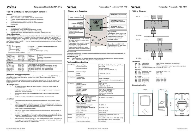
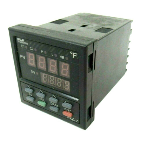
Fuji Electric PXH Series User manual

1
Fuji Electric Co.,Ltd.
Temperature Controller
MODBUS SIO Driver
1 System Configuration....................................................................................................... 3
2 External Device Selection ................................................................................................ 8
3 Communication Settings .................................................................................................. 9
4 Setup Items ....................................................................................................................25
5 Cable Diagrams ............................................................................................................. 30
6 Supported Devices......................................................................................................... 71
7 Device Code and Address Code.................................................................................... 76
8 Error Messages.............................................................................................................. 77

Temperature Controller MODBUS SIO Driver
GP-Pro EX Device/PLC Connection Manual 2
Introduction
This manual describes how to connect the Display and the External Device (target Temp. Controller).
In this manual, the connection procedure is described in the sections identified below:
1System Configuration
This section lists the types of External
Devices and SIO that you can connect.
)"1 System Configuration" (page 3)
2External Device Selection
Select a model (series) of the External
Device and its connection method.
)"2 External Device Selection" (page 8)
3Communication Settings
This section shows setting examples for
communicating between the Display and
the External Device.
)"3 Communication Settings" (page 9)
4Setup Items
This section describes communication
setup items on the Display.
Set the Display’s communication settings
in GP Pro-EX or in off-line mode.
)"4 Setup Items" (page 25)
5Cable Diagrams
This section shows cables and adapters
for connecting the Display and the
External Device.
)"5 Cable Diagrams" (page 30)
Operation

Temperature Controller MODBUS SIO Driver
GP-Pro EX Device/PLC Connection Manual 3
1 System Configuration
The following table lists system configurations for connecting Fuji Electric Co.,Ltd. External Devices and the
Display.
Series CPU Link I/F SIO Type Setting Example Cable
Diagram
PXH PXH-*1
*1 The CPU type can be connected with RS-422/485 (2 wire) when the section includes the following code:
R (RS-485)
PC Loader Port
on CPU Unit RS-232C "Setting Example 1"
(page 9)
" Cable
Diagram 1"
(page 30)
Port on CPU Unit RS-422/485
(2 wire)
"Setting Example 2"
(page 11)
" Cable
Diagram 2"
(page 32)
PXG
PXG4--*2
PXG5--*2
PXG9--*2
*2 The CPU type can be connected with RS-422/485 (2 wire) when the section includes the following codes:
M (RS-485)
V (RS-485 + Digital input (No.1))
K (RS-485 + RSV1)
J (RS-485 + CT1)
F (RS-485 + Digital input (No.1) + RSV1)
U (RS-485 + Digital input (No.1, 2, 3))
PC Loader Port
on CPU Unit RS-232C "Setting Example 3"
(page 13)
" Cable
Diagram 1"
(page 30)
Port on CPU Unit RS-422/485
(2 wire)
"Setting Example 4"
(page 15)
" Cable
Diagram 3"
(page 45)
PXR
(AutoFIX)
PXR3--*3
PXR4-*3*4*5
PXR5-*3
PXR7-*3
PXR9-*3
*3 The CPU type can be connected with RS-422/485 (2 wire) when the section includes the following codes:
M (RS-485 Modbus interface)
V (RS-485 Modbus interface + Digital input 1 point)
*4 PXR4 Socket type cannot be connected because it lacks a serial port option.
*5 CPU Unit released in July 2001 or later
Port on CPU Unit RS-422/485
(2 wire)
"Setting Example 5"
(page 17)
" Cable
Diagram 3"
(page 45)
PXR
(NoAuto-
FIX)
PXR4-*3*4*6
*6 CPU Unit released in June 2001 or earlier
Port on CPU Unit RS-422/485
(2 wire)
"Setting Example 6"
(page 19)
" Cable
Diagram 3"
(page 45)
PUM
PUMA-
PUMB-
PUME-
PUMV-
PUMN-
PUMT-
PC Loader Port
on CPU Unit RS-232C "Setting Example 7"
(page 21)
" Cable
Diagram 1"
(page 30)
Port on CPU Unit RS-422/485
(2 wire)
"Setting Example 8"
(page 23)
" Cable
Diagram 4"
(page 58)

Temperature Controller MODBUS SIO Driver
GP-Pro EX Device/PLC Connection Manual 4
Connection Configuration
• 1:1 Connection
• 1:n Connection
Display External Device
Display
External Device External Device External Device
Maximum number of External Devices: 16

Temperature Controller MODBUS SIO Driver
GP-Pro EX Device/PLC Connection Manual 5
IPC COM Port
When connecting IPC with an External Device, the COM port used depends on the series and SIO type. Please
refer to the IPC manual for details.
Usable port
Series
Usable Port
RS-232C RS-422/485(4 wire) RS-422/485(2 wire)
PS-2000B COM1*1 , COM2,
COM3*1, COM4
*1 The RI/5V can be switched. Use the IPC’s switch to change if necessary.
--
PS-3450A, PS-3451A,
PS3000-BA, PS3001-BD COM1, COM2*1*2 COM2*1*2 COM2*1*2
PS-3650A (T41 model),
PS-3651A (T41 model) COM1*1 --
PS-3650A (T42 model),
PS-3651A (T42 model) COM1*1*2, COM2 COM1*1*2 COM1*1*2
PS-3700A (Pentium®4-M)
PS-3710A
COM1*1, COM2*1,
COM3*2 , COM4
*2 Set up the SIO type with the DIP Switch. Please set up as follows according to SIO type to be used.
COM3*2 COM3*2
PS-3711A COM1*1, COM2*2 COM2*2 COM2*2
PS4000*3
*3 When making communication between an External Device and COM port on the Expansion slot,
only RS-232C is supported. However, ER (DTR/CTS) control cannot be executed because of the
specification of COM port.
For connection with External Device, use user-created cables and disable Pin Nos. 1, 4, 6 and 9.
Please refer to the IPC manual for details of pin layout.
COM1, COM2 - -
PL3000 COM1*1*2, COM2*1,
COM3, COM4 COM1*1*2 COM1*1*2
PE-4000B Atom N270 COM1, COM2 - -
PE-4000B Atom N2600 COM1, COM2 COM3*4 , COM4*4,
COM5*4, COM6*4
*4 Set up the SIO type with the BIOS. Please refer to the IPC manual for details of BIOS.
COM3*4, COM4*4,
COM5*4, COM6*4
PS5000 (Slim Panel Type
Core i3 Model) *5 *6 COM1, COM2*4 COM2*4 COM2*4
PS5000 (Slim Panel Type
Atom Model)
*5 *6
COM1, COM2*7 COM2*7 COM2*7
PS5000 (Enclosed Panel
Type)*8 COM1 - -
PS5000 (Modular Type
PFXPU/PFXPP)*5 *6
PS5000 (Modular Type
PFXPL2B5-6)
COM1*7 COM1*7 COM1*7
PS5000 (Modular Type
PFXPL2B1-4) COM1, COM2*7 COM2*7 COM2*7

Temperature Controller MODBUS SIO Driver
GP-Pro EX Device/PLC Connection Manual 6
DIP Switch settings (PL3000 / PS3000 Series)
RS-232C
*5 When setting up communication between an External Device and the RS-232C/422/485 interface
module, use the IPC (RS-232C) or PS5000 (RS-422/485) cable diagrams. However, when using
PFXZPBMPR42P2 in a RS-422/485 (4-wire) configuration with no flow control, connect 7.RTS+
and 8.CTS+, and connect 6.RTS- and 9.CTS-.
When using RS-422/485 communication with External Devices, you may need to reduce the
transmission speed and increase the TX Wait time.
*6 To use RS-422/485 communication on the RS-232C/422/485 interface module, the DIP Switch
setting is required. Please refer to "Knowledge Base" (FAQs) on the support site. (http://www.pro-
face.com/trans/en/manual/1001.html)
*7 Set up the SIO type with the DIP Switch. Please refer to the IPC manual for details of DIP Switch.
The BOX Atom has not a switch to set the RS-232C, RS-422/485 mode. Use the BIOS for the
setting.
*8 For the connection with the External Device, on the user-created cable read as if the connector on
the Display-side is a M12 A-coding 8 pin socket. The pin assignment is the same as described in
the cable diagram. For the M12 A-coding connector, use PFXZPSCNM122.
DIP Switch Setting Description
1OFF
*1
*1 When using PS-3450A, PS-3451A, PS3000-BA and PS3001-BD, turn ON the set value.
Reserved (always OFF)
2OFF
SIO type: RS-232C
3OFF
4 OFF Output mode of SD (TXD) data: Always output
5 OFF Terminal resistance (220Ω) insertion to SD (TXD): None
6 OFF Terminal resistance (220Ω) insertion to RD (RXD): None
7 OFF Short-circuit of SDA (TXA) and RDA (RXA): Not available
8 OFF Short-circuit of SDB (TXB) and RDB (RXB): Not available
9OFF
RS (RTS) Auto control mode: Disabled
10 OFF
Settings FAQ ID
PFXZPBMPR42P2, RS422/485 change method FA263858
PFXZPBMPR42P2 termination resistor setting FA263974
PFXZPBMPR44P2, RS422/485 change method FA264087
PFXZPBMPR44P2 termination resistor setting FA264088

Temperature Controller MODBUS SIO Driver
GP-Pro EX Device/PLC Connection Manual 7
RS-422/485 (4 wire)
RS-422/485 (2 wire)
DIP Switch Setting Description
1 OFF Reserved (always OFF)
2ON
SIO type: RS-422/485
3ON
4 OFF Output mode of SD (TXD) data: Always output
5 OFF Terminal resistance (220Ω) insertion to SD (TXD): None
6 OFF Terminal resistance (220Ω) insertion to RD (RXD): None
7 OFF Short-circuit of SDA (TXA) and RDA (RXA): Not available
8 OFF Short-circuit of SDB (TXB) and RDB (RXB): Not available
9OFF
RS (RTS) Auto control mode: Disabled
10 OFF
DIP Switch Setting Description
1 OFF Reserved (always OFF)
2ON
SIO type: RS-422/485
3ON
4 OFF Output mode of SD (TXD) data: Always output
5 OFF Terminal resistance (220Ω) insertion to SD (TXD): None
6 OFF Terminal resistance (220Ω) insertion to RD (RXD): None
7 ON Short-circuit of SDA (TXA) and RDA (RXA): Available
8 ON Short-circuit of SDB (TXB) and RDB (RXB): Available
9ON
RS (RTS) Auto control mode: Enabled
10 ON

Temperature Controller MODBUS SIO Driver
GP-Pro EX Device/PLC Connection Manual 8
2 External Device Selection
Select the External Device to be connected to the Display.
Setup Items Setup Description
Number of Devices/PLCs Enter an integer from 1 to 4 to define the number of Devices/PLCs to connect to the
display.
Manufacturer Select the manufacturer of the External Device to connect. Select "Fuji Electric
Co.,Ltd.".
Series
Select the External Device model (series) and the connection method. Select "Temp.
Controller MODBUS SIO".
In System configuration, make sure the External Device you are connecting is
supported by "Temp. Controller MODBUS SIO".
)"1 System Configuration" (page 3)
Port Select the Display port to be connected to the External Device.
Use System Area Not available for this driver.

Temperature Controller MODBUS SIO Driver
GP-Pro EX Device/PLC Connection Manual 9
3 Communication Settings
This section provides examples of communication settings recommended by Pro-face for the Display and the
External Device.
3.1 Setting Example 1
GP-Pro EX Settings
Communication Settings
To display the setup screen, from the [Project] menu, point to [System Settings] and select [Device/PLC].
Device Setting
To display the [Individual Device Settings] dialog box, from [Device-Specific Settings] in the [Device/PLC]
window, select the external device and click [Settings] .
To connect multiple External Devices, from [Device-Specific Settings] in the [Device/PLC] window, click [Add
Device] to add another External Device.

Temperature Controller MODBUS SIO Driver
GP-Pro EX Device/PLC Connection Manual 10
External Device Settings
For External Device communication settings, use the SEL key, UP key, DOWN key, Digit selection key, or DISP
key located in the operation area on the front of the controller.
Refer to your External Device manual for details.
1Press SEL key.
2Press UP key or DOWN key to display [COM].
3Press SEL key.
4Press UP key or DOWN key to display the setting parameter.
5Press SEL key to switch to setting mode.
6Press UP key, DOWN key or Digit selection key to display the setting value.
7Press SEL key.
8Press DISP key twice.
9Reboot the External Device.
Setting Value
Setting Parameter Setting Value Setup Description
SPD2 384 RS-232C communication speed
BIT2 8o RS-232C bit format

Temperature Controller MODBUS SIO Driver
GP-Pro EX Device/PLC Connection Manual 11
3.2 Setting Example 2
GP-Pro EX Settings
Communication Settings
To display the setup screen, from the [Project] menu, point to [System Settings] and select [Device/PLC].
Device Setting
To display the [Individual Device Settings] dialog box, from [Device-Specific Settings] in the [Device/PLC]
window, select the external device and click [Settings] .
To connect multiple External Devices, from [Device-Specific Settings] in the [Device/PLC] window, click [Add
Device] to add another External Device.

Temperature Controller MODBUS SIO Driver
GP-Pro EX Device/PLC Connection Manual 12
External Device Settings
For External Device communication settings, use the SEL key, UP key, DOWN key, Digit selection key, or DISP
key located in the operation area on the front of the controller.
Refer to your External Device manual for details.
1Press SEL key.
2Press UP key or DOWN key to display [COM].
3Press SEL key.
4Press UP key or DOWN key to display the setting parameter.
5Press SEL key to switch to setting mode.
6Press UP key, DOWN key or Digit selection key to display the setting value.
7Press SEL key.
8Press DISP key twice.
9Reboot the External Device.
Setting Value
Setting Parameter Setting Value Setup Description
STN4 1 RS-485 station No.
SPD4 384 RS-485 communication speed
BIT4 8o RS-485 bit format

Temperature Controller MODBUS SIO Driver
GP-Pro EX Device/PLC Connection Manual 13
3.3 Setting Example 3
GP-Pro EX Settings
Communication Settings
To display the setup screen, from the [Project] menu, point to [System Settings] and select [Device/PLC].
Device Setting
To display the [Individual Device Settings] dialog box, from [Device-Specific Settings] in the [Device/PLC]
window, select the external device and click [Settings] .
To connect multiple External Devices, from [Device-Specific Settings] in the [Device/PLC] window, click [Add
Device] to add another External Device.

Temperature Controller MODBUS SIO Driver
GP-Pro EX Device/PLC Connection Manual 14
External Device Settings
External Device communication settings are fixed as indicated below.
Setting Items Setting Value
Communication speed 9600
Data length 8
Stop bit 1
Parity None

Temperature Controller MODBUS SIO Driver
GP-Pro EX Device/PLC Connection Manual 15
3.4 Setting Example 4
GP-Pro EX Settings
Communication Settings
To display the setup screen, from the [Project] menu, point to [System Settings] and select [Device/PLC].
Device Setting
To display the [Individual Device Settings] dialog box, from [Device-Specific Settings] in the [Device/PLC]
window, select the external device and click [Settings] .
To connect multiple External Devices, from [Device-Specific Settings] in the [Device/PLC] window, click [Add
Device] to add another External Device.

Temperature Controller MODBUS SIO Driver
GP-Pro EX Device/PLC Connection Manual 16
External Device Settings
For External Device communication settings, use the SEL key, UP key, DOWN key, or USER key, located in the
operation area on the front of the controller.
Refer to your External Device manual for details.
1Press and hold SEL key to switch to Monitor Mode.
2Press and hold SEL key to switch to Setup Mode.
3Press UP key or DOWN key to display [CoM Ch 9].
4Press and hold SEL key.
5Press UP key or DOWN key to display setting parameter.
6Press SEL key.
7Press UP key or DOWN key to display setting value.
8Press SEL key.
9Press USER key.
10 Reboot the External Device.
Setting Value
Setting Parameter Setting Value Setup Description
STno 1 ST No. setting
CoM 96od RS-485 Baud rate/Parity settings
SCC rW RS-485 Communication permissions

Temperature Controller MODBUS SIO Driver
GP-Pro EX Device/PLC Connection Manual 17
3.5 Setting Example 5
GP-Pro EX Settings
Communication Settings
To display the setup screen, from the [Project] menu, point to [System Settings] and select [Device/PLC].
Device Setting
To display the [Individual Device Settings] dialog box, from [Device-Specific Settings] in the [Device/PLC]
window, select the external device and click [Settings] .
To connect multiple External Devices, from [Device-Specific Settings] in the [Device/PLC] window, click [Add
Device] to add another External Device.

Temperature Controller MODBUS SIO Driver
GP-Pro EX Device/PLC Connection Manual 18
External Device Settings
For External Device communication settings, use the SEL key, UP key, or DOWN key located in the operation
area on the front of the controller.
Refer to your External Device manual for details.
1Press and hold SEL key to display the 3rd block parameter.
2Press UP key or DOWN key to display setting parameter.
3Press SEL key.
4Press UP key or DOWN key to display setting value.
5Press SEL key.
6Press and hold SEL key.
Setting Value
Setting Parameter Setting Value Setup Description
STno 1 Station No.
CoM 0 Parity setting
PCoL 1 Communication protocol

Temperature Controller MODBUS SIO Driver
GP-Pro EX Device/PLC Connection Manual 19
3.6 Setting Example 6
GP-Pro EX Settings
Communication Settings
To display the setup screen, from the [Project] menu, point to [System Settings] and select [Device/PLC].
Device Setting
To display the [Individual Device Settings] dialog box, from [Device-Specific Settings] in the [Device/PLC]
window, select the external device and click [Settings] .
To connect multiple External Devices, from [Device-Specific Settings] in the [Device/PLC] window, click [Add
Device] to add another External Device.

Temperature Controller MODBUS SIO Driver
GP-Pro EX Device/PLC Connection Manual 20
External Device Settings
For External Device communication settings, use the SEL key, UP key, or DOWN key located in the operation
area on the front of the controller.
Refer to your External Device manual for details.
1Press and hold SEL key to display the 3rd block parameter.
2Press UP key or DOWN key to display setting parameter.
3Press SEL key.
4Press UP key or DOWN key to display setting value.
5Press SEL key.
6Press and hold SEL key.
Setting Value
Setting Parameter Setting Value Setup Description
STno 1 Station No.
CoM 0 Parity setting
PCoL 1 Communication protocol
This manual suits for next models
3
Table of contents
Other Fuji Electric Temperature Controllers manuals

Fuji Electric
Fuji Electric Micro-Controller X Socket type User manual

Fuji Electric
Fuji Electric PUMCL User manual

Fuji Electric
Fuji Electric PXZ Series User manual

Fuji Electric
Fuji Electric PUM Series User manual

Fuji Electric
Fuji Electric PXR3 Series User manual

Fuji Electric
Fuji Electric PUMCE User manual

Fuji Electric
Fuji Electric PXR3 Series User manual

Fuji Electric
Fuji Electric PXE4 User manual

Fuji Electric
Fuji Electric PXG5 User manual

Fuji Electric
Fuji Electric PXF4 User manual