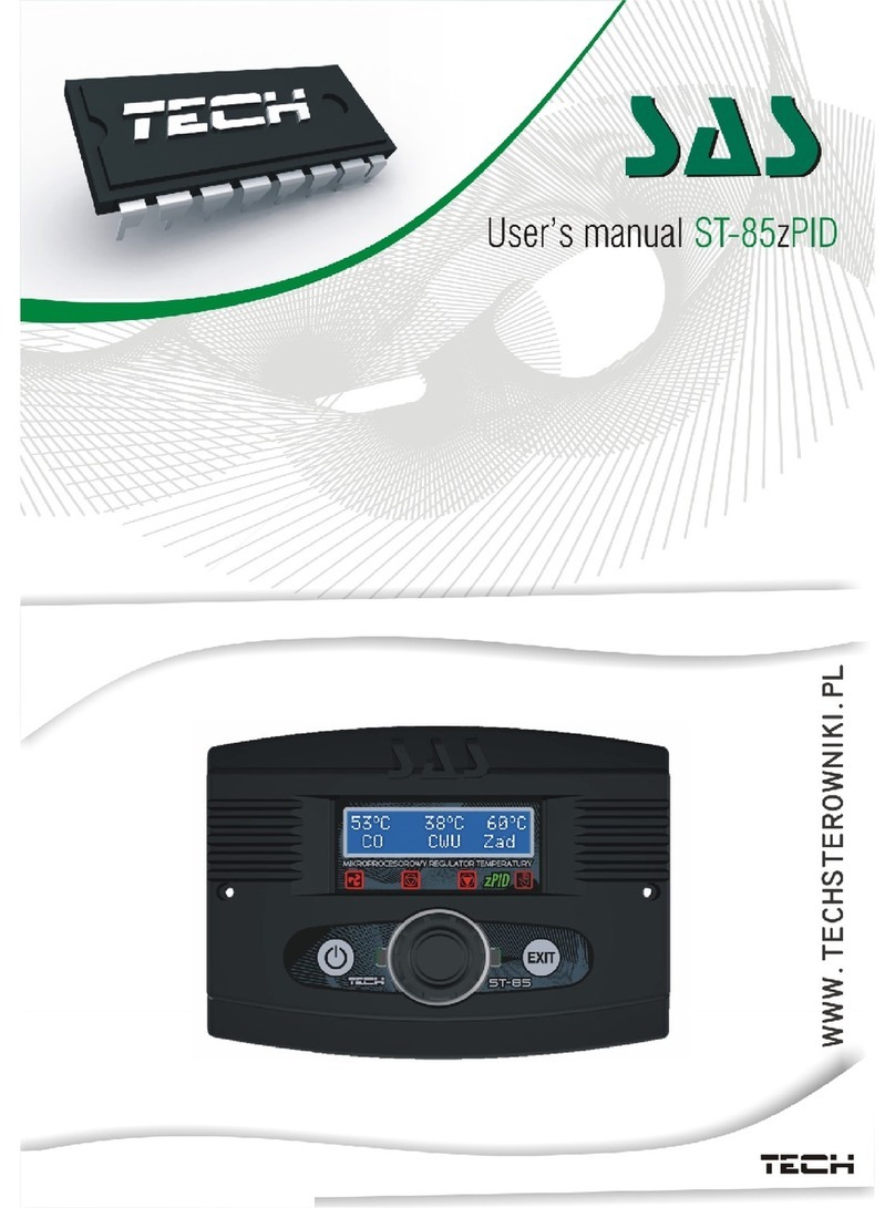
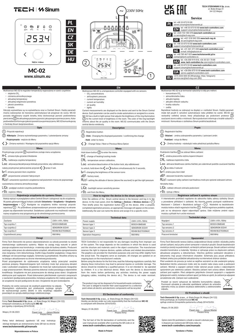
TECH ST-45 User manual

ST-44 USER’S MANUAL

ST-45 User's Manual
Declaration of Conformity No 27/2008
Hereby, we declare under sole responsibility that the ST-45
230V 50Hz thermoregulator manufactured by TECH, ul St
Batorego 14, 34-120 Andrychów, is compliant with the
Regulation by the Ministry of Economy (Journal of Laws Dz U
155 Item 1089) of July 21, 2007 implementing provisions of the
Low Voltage Directive (LVD) 2006/95/EC of January 16, 2007
The ST-45 controller has been tested for electromagnetic
compatibility (EMC) with optimal loads applied
For compliance assessment, harmonized standards were
used:
PN-EN 60730-2-9:2006.
Co-owners:
Paweł Jura Janusz Master
-2-

TECH
ATTENTION!
HIGH VOLTAGE!
Make sure the regulator is unplugged before
working on the power supply (cable connections
device installation etc.)!
All mounting works must only be carried out by
qualified electricians.
Before activating the controller measure the motor
resetting efficiency check the boiler and inspect
wire insulation.
CAUTION
THE DEVICE MAY BE DAMAGED IF STRUCK BY A
LIGHTNING. MAKE SURE IT IS UNPLUGGED
DURING STORMS
-3-

ST-45 User's Manual
I.Description
The ST-45 temperature regulator is intended for use with central heating
boilers It is used to control the water circulation pump, hot consumption
water pump, floor heating pump, mixing pump, blow (fan) and fuel
feeder The ST-45 regulator features two modules: graphic display panel
and control panel
The ST-45 can be used with two optional additional three-way or
four-way valve control modules. The regulator has been designed
and made for comfort.
It is very easy in use All parameters are adjusted with a convenient
knob (encoder) The ST-45 regulator features also a graphic display that
shows the current status of the boiler
If the furnace temperature is lower than the setpoint temperature, the
regulator is operated in its duty cycle, i e the blow is active and the
operation time of the fuel feeder is set by the user (both operation and
stand-by times are set)
If the furnace temperature is equal to or higher than the setpoint
-4-
Boiler Temp.
Water Heater
Temp.
Feeder; C.H.
Pump; H.C.W.
Pump; Fan
Button for accessing
submenus,
confirming settings
(encoder)
xit

TECH
temperature, the regulator is operated in its sustain cycle (both stand-
by and sustain mode times are to be set)
Please send all comments on the software to the boiler
manufacturer.
Your controller should be set according to your individual needs,
depending on the type of fuel and boiler used. TECH shall not be
held responsible for incorrect settings
II.Regulator Functionality
This chapter describes regulator functionality, how to change settings
and navigate in the menu with the encoder (knob) Depending on the
mode the boiler is currently in, the display will show boiler operational
parameters The given mode is selected by the user
While the user is logging in, the display shows the manufacturer and the
software version
After several seconds, you can select your language With this function,
you can change the language version
II.1.Main Page
During normal operation, the graphic display shows the main page with
the following data:
-5-
LANGUAGE VERSION
Exit
Polish
English

ST-45 User's Manual
Boiler temperature (actual to the left; setpoint to the right)
Pressing the encoder will move you to the first level The display shows
three options of the menu To move to next options, turn the knob
clockwise In order to exit the menu, select EXIT (only in the edit mode)
In order to apply any changes, they need to be confirmed by pressing the
encoder on the CONFIRM message If you do not wish to make any
changes in a given function, press the encoder on the CANCEL message
II.2.C.H. Setpoint Temperature
With this function, you can set the boiler temperature You can change
the boiler temperature in a range between 45°C and 80°C
II.3.H.C.W. Setpoint Temperature
With this function, you can set the hot consumption water temperature
You can change the boiler temperature in a range between 40°C and
75°C
-6-
HOUSE HEATING
C H H C W
MENU
Exit
C H Setpoint
H C W Setpoint
Screen Display
MENU
Exit
C H Setpoint
H C W Setpoint
Screen Display

TECH
II.4.Screen
With this function, you can select one of three main screens to control
the thermoregulator The C.H. screen is used for displaying the current
boiler status
The valve 1 screen is used for displaying parameters of the first valve
The valve 2 screen is used for displaying parameters of the second
valve
II.5.Manual Mode
For your convenience, the regulator features a manual mode module In
this mode, each individual element is enabled and disabled independently
of the other
Pressing the ENCODER will enable the fuel feeder The feeder will
operate until the ENCODER is pressed again
-7-
MENU
Exit
C H Setpoint
H C W Setpoint
Screen Display
HOUSE HEATING
VALVE
VALVE TEMP
SETPOINT TEMP
OPENING
MENU
Exit
Manual Mode
Feed Time
Feed Pause

ST-45 User's Manual
Press the ENCODER to enable / disable the blow
Press the ENCODER to enable / disable the central heating pump
Press the ENCODER to enable / disable the (water heater) hot
consumption water pump
Press the ENCODER to enable / disable the floor heating pump
Press the ENCODER to enable / disable the mixing pump
Press the ENCODER to enable / disable the alarm
II.6.Feed Time
With this function, you can set the operation time for the fuel feeder Set
the operation time according to the type of fuel and boiler used
II.7.Feed Interval
With this function, you can set the stand-by time for the feeder,
depending on the type of fuel used in the boiler Incorrect operation and
stand-by times may cause the boiler to malfunction, i e inability to burn
all carbon and to reach the setpoint temperature Setting correct times
will ensure correct boiler operation
II.8.Blow Force
With this function, you can control the fan speed The adjustment range
is from 10 to 100% (it can be assumed that the fan operates in gears)
-8-
MENU
Exit
Manual Mode
Feed Time
Feed Pause
MENU
Exit
Blow Force
Operation Mode
Sustain Mode

TECH
The higher the gear, the higher the speed with 10% being the minimum
and the 100% being the maximum speed of the fan
Initially, the fan runs always at full speed so that it is possible to start it
with the motor being slightly dusty
II.9.Operation Mode
With this function, you can select one out of four operation modes
II.9.a)House Heating
If you select this option, the regulator will switch into the house heating
mode The central heating pump starts to run above the pump activation
threshold (set to 40°C by default) Below this temperature, the pump is
shut off
II.9.b) Water Heater Priority
-9-
MENU
Exit
Blow Force
Operation Mode
Sustain Mode
HOUSE HEATING
C H H C W
WATER HEATER PRIORITY
C H H C W

ST-45 User's Manual
If you select this option, the regulator will switch into the water heater
priority mode Activating the hot consumption water pump will cause the
regulator to switch into the water heater priority mode In this mode, the
(hot consumption water) heater pump is activated until the set
temperature is reached Then, the pump is shut off and the central
heating circulation pump is activated
In order to activate the hot consumption water pump, it is necessary to
raise the setpoint temperature above the pump activation threshold (the
pump activation threshold to be adjusted in the service menu)
The temperature can be changed in the H.C.W Set function (see point
II 2)
In this mode, the fan and the feeder are operated as long as the
temperature is below 62°C to prevent the boiler from overheating Such
condition will be maintained until the water heater setpoint temperature
is reached When the temperature is reached, the hot consumption water
pump is shut off and the central heating pump is activated
The central heating pump will run until the water heater temperature
drops below the setpoint value; then, the central heating pump is shut
off and the hot consumption water pump is activated
The hot consumption water priority function consists in that the
consumption water is heated up before heating up water in radiators
ATTENTION: the boiler should have non-return valves mounted on the
central heating pump and hot consumption water pump circuits A valve
mounted on the pump will prevent the hot consumption water from being
discharged from the water heater A valve mounted on the central
heating circuit will not let the hot consumption water move from the
water heater into the house circuit
-10-

TECH
II.9.c) Parallel Pumps
In this mode, the pumps run initially in parallel above the pump
activation threshold (set to 40°C by default) The central heating pump
continues to run and the hot consumption water pump is shut off after
the water heater setpoint temperature has been reached
ATTENTION: in this mode, you should mount a three-way valve or a
mixing valve that will maintain different temperatures in the water heater
and in the house
II.9.d) Summer Mode
When the function is enabled, the central heating pump is switched off
and the hot consumption water pump is activated above the pump
activation threshold (set to 40°C by default) In this mode, the hot
consumption water pump continues to run above the pump activation
threshold (set to 40°C by default) In the summer mode, the water
heater setpoint temperature is to be set When the summer mode is
disabled, the actual temperature of the central heating and two
temperatures (actual and setpoint) of the hot consumption water are
displayed
II.10.Sustain Mode Operation
With this function, you can set the operation time for the fuel feeder and
the fan
-11-
SUMMER MODE
C H H C W

ST-45 User's Manual
II.11.Pause in Sustain Mode
With this function, you can set the pause of the feeder in the sustain
mode
The function is used for regulating the furnace while in the sustain
mode This is to prevent damping of the furnace when the boiler
temperature is over the setpoint value
ATTENTION: incorrect settings may cause a continuous increase of the
temperature! Especially the Pause in Sustain ode should not bee too
short
II.12.Sustain Mode of Fan
In this function, you can set the operation time and the pause time for
the fan while in the burnout mode
III.Fitter’s Menu
The fitter’s menu parameters are to be set by the boiler fitter or service
personnel provided by Sas
-12-
MENU
Exit
Sustain Pause
Fan Sustain
Fitter’s Menu
MENU
Exit
Sustain Pause
Fan Sustain
Fitter’s Menu
MENU
Exit
Sustain Pause
Fan Sustain
Fitter’s Menu

TECH
III.1.Factory Settings
The regulator has been pre-configured However, it should be adjusted to
your individual needs It is possible to return to the factory settings at
any time By enabling factory settings, all boiler settings that you have
made will be replaced by settings made by the manufacturer From then
on, you can again set your own operating parameters for the boiler
III.2.Valves 1 and 2
With this function, you can set the operation time for the mixing (three-
or four-way) valve only with modules ST-61 For the valve to operate
properly and as required, it is necessary to set several parameters
III.2.a) Registration
In this function, the fitter enters the serial number of the control module
used with the three-way valve actuator (ST-61, five-digit number
provided on the module housing) Without entering the number, the
function will be disabled
-13-
FITTER’S MENU
Exit
Factory Settings
Valve 1
Valve 2
VALVE
Exit
Registration
Temp Monitor
Opening Time
FITTER’S MENU
Exit
Factory Settings
Valve 1
Valve 2

ST-45 User's Manual
III.2.b) Temperature Monitoring
In this function, you can set the temperature monitoring time for water
that is delivered downstream of the valve to heat the house This means
that the temperature downstream of the valve is checked periodically If
decrease of the temperature is detected, the valve will be opened by a
defined amount in order to heat up the house The above principle also
serves the opposite purpose when there is a need of decreasing the
temperature
III.2.c) Opening Time
This function can be used for setting the opening time for the valve, i e
how long is it going to take for the valve to be fully opened
-14-
REGISTRATION
Enter Module Number
C.H. VALVE
Calibrating valve
Please wait
VALVE
Exit
Registration
Temp Monitor
Opening Time
TEMP MONITOR
seconds
OPENING TIME
seconds

TECH
III.2.d) Single stroke
This function can be used for setting the opening stroke for the valve, i e
by what percent is the valve to be opened or closed
III.2.e) Minimum opening
With this function, you can set the minimum value for closing of the
valve The valve cannot be closed further than this value
III.2.f) Valve Type
With this function, you can select the valve type, either the central
heating valve or the floor heating valve By selecting the latter,
temperature rise is limited to 50°C in order to ensure safety in case of
floor heating
III.3.Temperature Alarm
-15-
SINGLE STROKE
%
MINIMUM OPENING
%
FITTER’S MENU
Exit
Factory Settings
Valve 1
Valve 2
VALVE TYPE
Exit
C H Valve
Floor Valve

ST-45 User's Manual
The function is enabled only in the duty mode (i e when the boiler
temperature is lower than the setpoint temperature) When the boiler
temperature fails to rise in the user-defined period, an alarm is
activated: the feeder and the fan are shut off (the water pump is
switched on and off independently) and the alarm is sounded The
display shows the following message: C H Temperature Rise Failed The
alarm can be reset with the encoder
III.4.Room Regulator
The ST-45 regulator can be connected to a room regulator In such case,
it has a higher priority, which does not apply to heating from the water
heater The feeder, fan and central heating pup run until the temperature
set with the room regulator is reached However, the boiler is limited in
its operation by the temperature set with the boiler controller
CONNECTING THE ROOM REGULATOR: the room regulator features a
two-wire cable that should be connected to the controller's connection
strip, to a terminal labelled as room regulator
ATTENTION: no external voltage can be applied to the room regulator
output
III.5.Boiler Hysteresis
With this function, you can set the hysteresis of the setpoint
-16-
FITTER’S MENU
Exit
Temperature Alarm
Room Regulator
Boiler Hysteresis
FITTER’S MENU
Exit
Temperature Alarm
Room Regulator
Boiler Hysteresis

TECH
temperature This is a difference between the temperature of entering
into the sustain cycle and the temperature of returning to the duty cycle
(e g : when the setpoint temperature is set to 60°C, and the hysteresis is
set to 3°C, entering into the sustain cycle will be effected after the
temperature reaches 60°C, whereas return to the duty cycle will be
effected after the temperature drops to 57°C)
III.6.H.C.W. Hysteresis
With this function, you can set the hysteresis of the setpoint temperature
on the water heater
This is a difference between the setpoint temperature (required by the
water heater) and the actual temperature on the water heater (e g :
when the setpoint temperature is set to 55oC and the hysteresis is set to
5oC) After reaching the setpoint temperature, i e 55°C, the hot
consumption water pump is shut off, causing the central heating pump to
be activated The hot consumption water pump will be activated again
when the temperature drops to 50°C
III.7.Floor Heating Pump
With this function, you can control the floor heating You can set the floor
-17-
FITTER’S MENU
Exit
H C W Hysteresis
Floor Pump
Circulation Pump
FITTER’S MENU
Exit
H C W Hysteresis
Floor Pump
Circulation Pump
FLOOR PUMP
Exit
On
Off
Min Temperature

ST-45 User's Manual
heating temperature in a range between 20°C and 55°C You can also set
the pump switch-on and shut-off threshold, e g 25°C, meaning that
when the temperature drops below this value, the pump is shut off, and
when it rises above this value, the pump runs until the setpoint
temperature is reached When the setpoint temperature has been
reached, e g 45°C, the floor heating pump is shut off The floor heating
pump will be re-activated when the temperature drops to 2°C)
III.8.Circulation Pump
With this function, you can control the pump that is responsible for
mixing hot water between the boiler and hot consumption water
receivers Operation and pause times are set by the user
III.9.Automatic Mode of Feeder
With this function, you can disable or enable the automatic feed (e g in
order to damp the boiler)
-18-
FITTER’S MENU
Exit
H C W Hysteresis
Floor Pump
Circulation Pump
CIRCULATION PUMP
Exit
On
Off
Operation Time
FITTER’S MENU
Exit
Feeder in Auto Mode
Language Version
Software Version

TECH
III.10.Language Version
With this function, you can change the language version
III.11.Software Version
With this function, you can check the software version for a given
thermoregulator
IV.Service Menu
To be able access service functions of the ST-45 controller, you need to
enter a four-digit code The code is available from Sas or Tech
IV.1.Pump Switch-on Temperature
-19-
FITTER’S MENU
Exit
Feeder in Auto Mode
Language Version
Software Version
LANGUAGE VERSION
Exit
Polish
English
SERVICE MENU
Exit
Pump Activation Temp
Feeder Alarm Temp
Priority Temp
PUMP ACTIVATION TEMP
degrees
SERVICE MENU
Enter Access Code

ST-45 User's Manual
With this function, you can set the temperature for central heating pump
and hot consumption water pump activation (This is the temperature
measured on the boiler) Below the set temperature (-2°C), the pumps
are inoperative, and above the setpoint value, the pumps are activated
but they operate according to the selected mode
IV.2.Feeder Alarm Temperature
With this protective function, you can set the alarm temperature for the
fuel feeder If the feeder temperature rises unexpectedly, this can be due
to the presence of fire in the feeder After the feeder alarm temperature
is reached, the feeder starts to run in order to discharge the burning
material into the furnace
IV.3.Priority Temperature
With this function, you can set the temperature in the hot consumption
water heating priority The temperature adjustment range is 50-75°C
-20-
SERVICE MENU
Exit
Pump Activation Temp
Feeder Alarm Temp
Priority Temp
FEEDER ALARM TEMP
degrees
SERVICE MENU
Exit
Pump Activation Temp
Feeder Alarm Temp
Priority Temp
PRIORITY TEMP
degrees
Table of contents
Other TECH Temperature Controllers manuals
Popular Temperature Controllers manuals by other brands
Full Gauge Controls
Full Gauge Controls TC-940Ri manual

Auber Instruments
Auber Instruments WSD-1200H quick guide

Ahlborn
Ahlborn ALMEMO 1030 operating instructions

CD Automation
CD Automation Revo TC 2ph user manual

AMX
AMX AXC-TEMP AND RTS-1 TEMPERATURE CONTROL CARD AND ROOM TEMPERATURE... instruction manual

TE Technology
TE Technology TC-48-20 instruction manual

MISSION CONTROLS
MISSION CONTROLS LOGiCFAN User instructions

Kerda
Kerda AL8010F user manual

RKC INSTRUMENT
RKC INSTRUMENT SRZ Z-TIO-A instruction manual

Vexve
Vexve AUTOMIX 10 Mounting and operating instructions

Store It Cold
Store It Cold CoolBot Quick start setup guide

Sorel
Sorel TDC 1 Installation and operating instructions