Fuji General Limited GENERAL ASHG07KPCA Service manual

AIR CONDITIONER
Wall mounted type
DESIGN & TECHNICAL MANUAL
INDOOR
ASHG07KPCA
ASHG09KPCA
ASHG12KPCA
OUTDOOR
AOHG07KPCA
AOHG09KPCA
AOHG12KPCA
DR_AS089EG_02
2019.02.25

Notices:
• Product specifications and design are subject to change without notice for future improvement.
• For further details, please check with our authorized dealer.
Copyright © 2019 Fujitsu General Limited. All rights reserved.

CONTENTS
Part 1. INDOOR UNIT...........................................................................1
1. Specifications................................................................................................2
2. Dimensions....................................................................................................4
2-1. Models: ASHG07KPCA, ASHG09KPCA, and ASHG12KPCA.........................................4
3. Wiring diagrams ............................................................................................6
3-1. Models: ASHG07KPCA, ASHG09KPCA, and ASHG12KPCA.........................................6
4. Capacity table................................................................................................7
4-1. Cooling capacity...............................................................................................................7
4-2. Heating capacity ..............................................................................................................8
5. Fan performance ...........................................................................................9
5-1. Air velocity distributions....................................................................................................9
5-2. Airflow ............................................................................................................................11
6. Operation noise (sound pressure).............................................................13
6-1. Noise level curve............................................................................................................13
6-2. Sound level check point .................................................................................................14
7. Safety devices .............................................................................................15
8. Remote controller .......................................................................................16
8-1. Wireless remote controller .............................................................................................16
9. Function settings ........................................................................................18
9-1. Function settings by using remote controller..................................................................18
9-2. Custom code setting for wireless remote controller........................................................23
10. Accessories.................................................................................................24
11. Optional parts .............................................................................................25
11-1.Others ...........................................................................................................................25

Part 2. OUTDOOR UNIT.....................................................................27
1. Specifications..............................................................................................28
2. Dimensions..................................................................................................29
2-1. Models: AOHG07KPCA, AOHG09KPCA, and AOHG12KPCA......................................29
3. Installation space ........................................................................................30
3-1. Models: AOHG07KPCA, AOHG09KPCA, and AOHG12KPCA......................................30
4. Refrigerant circuit .......................................................................................33
4-1. Models: AOHG07KPCA, AOHG09KPCA, and AOHG12KPCA......................................33
5. Wiring diagrams ..........................................................................................34
5-1. Models: AOHG07KPCA, AOHG09KPCA, and AOHG12KPCA......................................34
6. Capacity compensation rate for pipe length and height difference........35
6-1. Models: AOHG07KPCA and AOHG09KPCA.................................................................35
6-2. Model: AOHG12KPCA...................................................................................................36
7. Additional charge calculation ....................................................................37
7-1. Models: AOHG07KPCA and AOHG09KPCA.................................................................37
7-2. Model: AOHG12KPCA...................................................................................................37
8. Airflow..........................................................................................................38
8-1. Model: AOHG07KPCA...................................................................................................38
8-2. Model: AOHG09KPCA...................................................................................................38
8-3. Model: AOHG12KPCA...................................................................................................39
9. Operation noise (sound pressure).............................................................40
9-1. Noise level curve............................................................................................................40
9-2. Sound level check point .................................................................................................41
10. Electrical characteristics............................................................................42
11. Safety devices .............................................................................................43
12. Accessories.................................................................................................44
12-1.Models: AOHG07KPCA, AOHG09KPCA, and AOHG12KPCA.....................................44
CONTENTS (continued)

Part 1. INDOOR UNIT
WALL MOUNTED TYPE:
ASHG07KPCA
ASHG09KPCA
ASHG12KPCA

1. Specifications
Type
Wall mounted
Inverter heat pump
Model name ASHG07KPCA ASHG09KPCA ASHG12KPCA
Power supply 230 V ~ 50 Hz
Power supply intake Outdoor unit
Available voltage range 198—264 V
Capacity
Cooling
Rated kW 2.00 2.50 3.40
Btu/h 6,800 8,500 11,600
Min.—Max. kW 0.9—2.8 0.9—3.0 0.9—3.7
Btu/h 3,100—9,600 3,100—10,200 3,100—12,600
Heating
Rated kW 2.50 2.80 3.80
Btu/h 8,500 9,500 13,000
Min.—Max. kW 0.9—3.4 0.9—3.8 0.9—4.80
Btu/h 3,100—11,600 3,100—12,900 3,100—16,400
Input power
Cooling Rated
kW
0.48 0.71 1.00
Min.—Max. 0.25—1.03 0.25—1.05 0.25—1.14
Heating Rated 0.63 0.79 1.14
Min.—Max. 0.25—1.39 0.25—1.39 0.25—1.60
Fan
HIGH
W
21.5 26.9
MED 12.5 14.5
LOW 6.3 7.1
QUIET 3.0 3.0
Current Cooling Rated A 2.7 3.5 4.7
Heating 3.2 3.8 5.6
EER Cooling kW/kW 4.17 3.52 3.40
COP Heating 3.97 3.54 3.33
Sensible capacity Cooling kW 1.9 2.1 2.6
Power factor Cooling %77 87 92
Heating 85 90 89
Moisture removal L/h (pints/h) 1.0 (1.8) 1.3 (2.30) 1.8 (3.20)
Maximum operating current *1 Cooling A6.5 6.5 6.5
Heating 9.0 9.0 9.0
Fan
Airflow rate
Cooling
HIGH
m3/h
580 580 630
MED 460 460 490
LOW 340 340 360
QUIET 240 240 240
Heating
HIGH 580 580 630
MED 460 460 490
LOW 380 380 380
QUIET 260 260 260
Type × Q'ty Cross flow fan × 1
Motor output W 27 27 27
Sound pressure level *2
Cooling
HIGH
dB (A)
45 45 46
MED 38 38 40
LOW 31 31 33
QUIET 22 22 22
Heating
HIGH 45 45 46
MED 40 40 40
LOW 36 36 35
QUIET 26 26 27
Heat exchanger type
Dimensions (H × W × D) mm 210 × 600 × 26.6
Fin pitch 1.3
Rows × Stages 2 × 10
Pipe type Copper tube
Fin type Aluminum
Enclosure
Material Polystyrene
Color White
Approximate color of Munsell N 9.25/
Dimensions
(H × W × D)
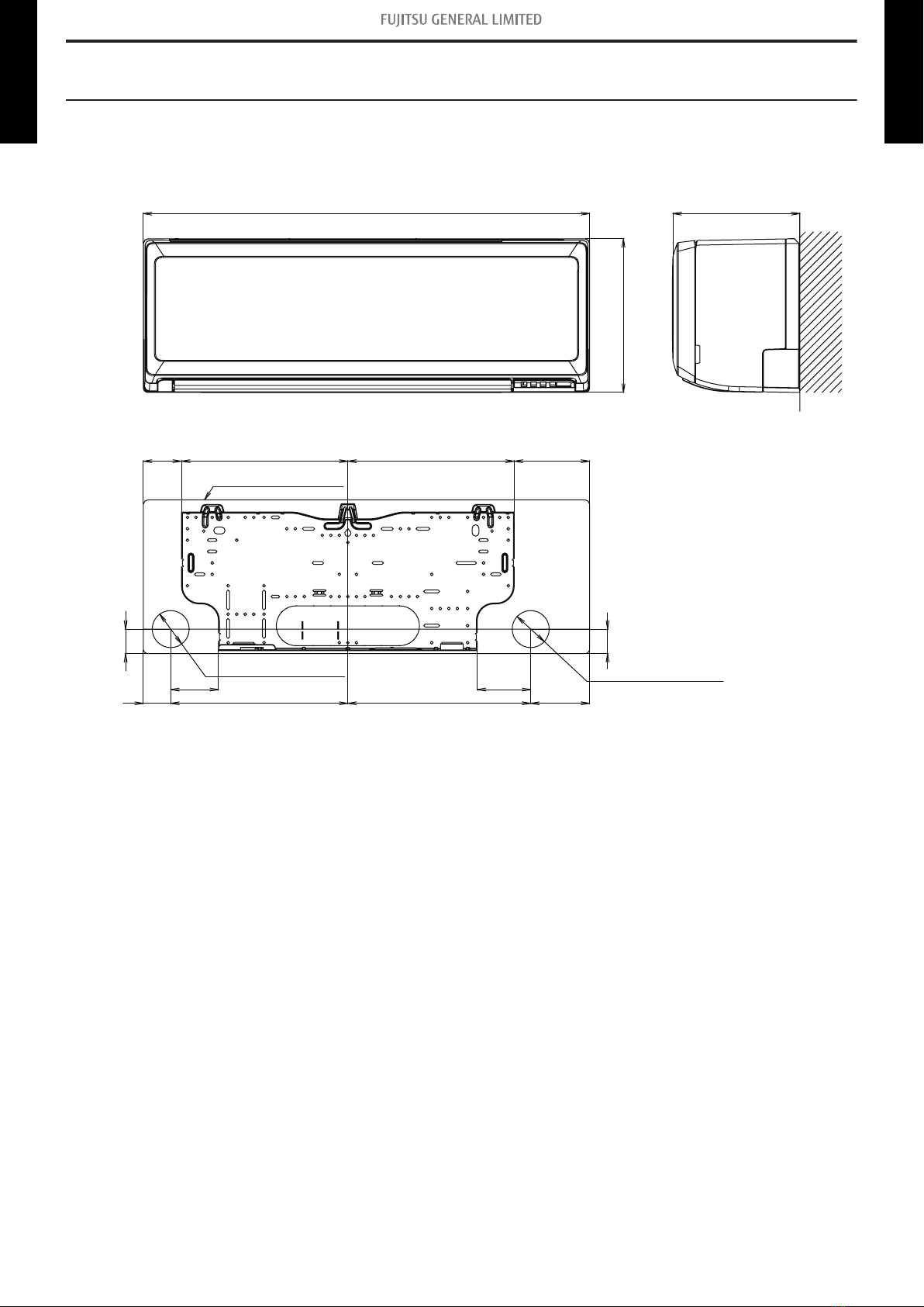
Net mm 270 × 784 × 224
Gross 279× 864 × 334
Weight Net kg 8.0
Gross 11.0
Connection pipe Size Liquid mm (in) Ø 6.35 (1/4)
Gas Ø 9.52 (3/8)
Method Flare
Drain hose Material PP+HDPE
Size mm Ø 11.8 (I.D.), Ø 15 to Ø 16.8 (O.D.)
Operation range Cooling °C 18 to 32
%RH 80 or less
Heating °C 16 to 30
Remote controller type Wireless
NOTES:
• Specifications are based on the following conditions:
– Cooling: Indoor temperature of 27 °CDB/19 °CWB, and outdoor temperature of 35 °CDB/24 °CWB.
– Heating: Indoor temperature of 20 °CDB/15 °CWB, and outdoor temperature of 7 °CDB/6 °CWB.
– Pipe length: 5 m, Height difference: 0 m. (Between outdoor unit and indoor unit.)
• Protective function might work when using it outside the operation range.
• *1: Maximum current is maximum value when operated within the operation range.
• *2: Sound pressure level:
– Measured values in manufacturer’s anechoic chamber.
– Because of the surrounding sound environment, the sound levels measured in actual installation conditions might be higher than the specified values here.
- 2 - 1. Specifications
WALL MOUNTED
ASHG07-12KPCA
WALL MOUNTED
ASHG07-12KPCA

Specifications for Lot10
Model name ASHG07KPCA ASHG09KPCA ASHG12KPCA
Energy efficiency class Cooling A++
Heating (Average) A+
P design Cooling kW 2.0 (35 °C) 2.5 (35 °C) 3.4 (35 °C)
Heating (Average) 2.2 (-10 °C) 2.4 (-10 °C) 2.5 (-10 °C)
SEER Cooling kWh/kWh 6.7 6.7 6.3
SCOP Heating (Average) 4.0 4.0 4.1
Annual energy consumption QCE kWh/a 104 131 189
QHE (Average) 769 840 853
Sound power level Cooling HIGH dB (A) 57 58 59
Heating 58 58 59
- 3 - 1. Specifications
WALL MOUNTED
ASHG07-12KPCA
WALL MOUNTED
ASHG07-12KPCA

2. Dimensions
2-1. Models: ASHG07KPCA, ASHG09KPCA, and ASHG12KPCA
Unit: mm
784 224
Outline of indoor unit
for pipe inlet Ø65
for pipe inlet Ø65
43
43
292 13329267
10432148 311 94
84
270
- 4 -
2-1. Models: ASHG07KPCA, ASHG09KPCA, and ASHG12KPCA 2. Dimensions
WALL MOUNTED
ASHG07-12KPCA
WALL MOUNTED
ASHG07-12KPCA

¢Installation space requirement
Provide sufficient installation space for product safety.
Unit: mm
Wall hook bracket
Outline of the indoor unit
50 or more
67 or more
The flare connection
part should be installed
outdoors.
40 or more
30 or more
107 or more
1,500 or more
1,800 or more
163 or more
- 5 -
2-1. Models: ASHG07KPCA, ASHG09KPCA, and ASHG12KPCA 2. Dimensions
WALL MOUNTED
ASHG07-12KPCA
WALL MOUNTED
ASHG07-12KPCA

3. Wiring diagrams
3-1. Models: ASHG07KPCA, ASHG09KPCA, and ASHG12KPCA
- 6 -
3-1. Models: ASHG07KPCA, ASHG09KPCA, and ASHG12KPCA 3. Wiring diagrams
WALL MOUNTED
ASHG07-12KPCA
WALL MOUNTED
ASHG07-12KPCA

4. Capacity table
Capacity tables show each of following values calculated based on the outdoor temperature and the
indoor temperature, under given Airflow Rate (AFR):
For cooling capacity: Total Capacity (TC), Sensible Heat Capacity (SHC), and Input Power (IP)
For heating capacity: Total Capacity (TC) and Input Power (IP)
4-1. Cooling capacity
¢Model: ASHG07KPCA
AFR m3/h 580
Indoor temperature
°CDB 18 21 23 25 27 29 32
°CWB 12 15 16 18 19 21 23
Outdoor temperature
°CDB TC SHC IP TC SHC IP TC SHC IP TC SHC IP TC SHC IP TC SHC IP TC SHC IP
kW kW kW kW kW kW kW
-10 1.49 1.03 0.22 1.65 1.04 0.23 1.71 1.13 0.23 1.82 1.13 0.23 1.88 1.22 0.23 1.99 1.22 0.23 2.11 1.30 0.23
0 1.56 1.09 0.28 1.74 1.09 0.28 1.80 1.19 0.29 1.92 1.19 0.29 1.98 1.29 0.29 2.10 1.28 0.29 2.22 1.37 0.30
5 1.57 1.09 0.28 1.75 1.10 0.28 1.81 1.19 0.28 1.93 1.20 0.28 1.99 1.29 0.29 2.11 1.29 0.29 2.23 1.37 0.29
10 1.58 1.10 0.27 1.76 1.10 0.27 1.82 1.20 0.28 1.94 1.20 0.28 2.00 1.30 0.28 2.12 1.29 0.28 2.24 1.38 0.29
15 1.73 1.22 0.30 1.92 1.22 0.31 1.99 1.33 0.31 2.12 1.34 0.31 2.18 1.44 0.31 2.32 1.44 0.32 2.45 1.53 0.32
20 1.87 1.32 0.34 2.09 1.33 0.34 2.16 1.45 0.34 2.30 1.45 0.35 2.37 1.57 0.35 2.51 1.56 0.35 2.65 1.66 0.36
25 1.78 1.26 0.38 1.98 1.26 0.38 2.05 1.37 0.39 2.18 1.38 0.39 2.25 1.49 0.39 2.39 1.48 0.40 2.52 1.58 0.40
30 1.68 1.19 0.42 1.87 1.19 0.43 1.94 1.30 0.43 2.06 1.30 0.43 2.13 1.41 0.44 2.25 1.40 0.44 2.38 1.49 0.44
35 1.58 1.12 0.46 1.76 1.12 0.47 1.82 1.22 0.47 1.94 1.23 0.48 2.00 1.32 0.48 2.12 1.32 0.48 2.24 1.40 0.49
40 1.52 1.00 0.46 1.70 1.00 0.47 1.75 1.09 0.47 1.87 1.09 0.48 1.93 1.18 0.48 2.04 1.17 0.48 2.16 1.25 0.49
46 1.47 0.92 0.46 1.64 0.93 0.47 1.69 1.01 0.47 1.80 1.01 0.48 1.86 1.09 0.48 1.97 1.09 0.48 2.08 1.16 0.49
¢Model: ASHG09KPCA
AFR m3/h 580
Indoor temperature
°CDB 18 21 23 25 27 29 32
°CWB 12 15 16 18 19 21 23
Outdoor temperature
°CDB TC SHC IP TC SHC IP TC SHC IP TC SHC IP TC SHC IP TC SHC IP TC SHC IP
kW kW kW kW kW kW kW
-10 1.82 1.25 0.25 2.03 1.26 0.25 2.10 1.36 0.25 2.24 1.37 0.26 2.31 1.48 0.26 2.45 1.47 0.26 2.59 1.57 0.26
0 1.91 1.31 0.34 2.13 1.31 0.35 2.20 1.43 0.35 2.35 1.43 0.35 2.42 1.55 0.36 2.57 1.54 0.36 2.71 1.64 0.36
5 1.88 1.28 0.33 2.09 1.29 0.33 2.16 1.40 0.33 2.30 1.41 0.34 2.38 1.52 0.34 2.52 1.51 0.34 2.66 1.61 0.34
10 1.84 1.26 0.31 2.05 1.27 0.31 2.12 1.38 0.32 2.26 1.38 0.32 2.33 1.49 0.32 2.47 1.49 0.32 2.61 1.58 0.33
15 2.09 1.21 0.40 2.33 1.21 0.41 2.41 1.32 0.41 2.57 1.32 0.42 2.65 1.43 0.42 2.80 1.43 0.42 2.96 1.52 0.43
20 2.34 1.63 0.50 2.61 1.63 0.51 2.70 1.78 0.51 2.87 1.78 0.51 2.96 1.93 0.52 3.14 1.92 0.52 3.32 2.04 0.53
25 2.22 1.54 0.56 2.48 1.55 0.57 2.56 1.69 0.57 2.73 1.69 0.58 2.81 1.83 0.58 2.98 1.82 0.59 3.15 1.94 0.59
30 2.10 1.45 0.62 2.34 1.46 0.63 2.42 1.59 0.63 2.58 1.60 0.64 2.66 1.72 0.64 2.82 1.72 0.65 2.98 1.83 0.66
35 1.98 1.37 0.69 2.20 1.38 0.70 2.28 1.50 0.70 2.43 1.50 0.71 2.50 1.62 0.71 2.65 1.61 0.72 2.80 1.72 0.72
40 1.90 1.22 0.68 2.12 1.23 0.70 2.19 1.33 0.70 2.34 1.34 0.71 2.41 1.44 0.71 2.55 1.44 0.72 2.70 1.53 0.72
46 1.84 1.13 0.68 2.04 1.14 0.69 2.11 1.24 0.70 2.25 1.24 0.70 2.32 1.34 0.71 2.46 1.33 0.71 2.60 1.42 0.72
¢Model: ASHG12KPCA
AFR m3/h 630
Indoor temperature
°CDB 18 21 23 25 27 29 32
°CWB 12 15 16 18 19 21 23
Outdoor temperature
°CDB TC SHC IP TC SHC IP TC SHC IP TC SHC IP TC SHC IP TC SHC IP TC SHC IP
kW kW kW kW kW kW kW
-10 2.65 1.79 0.41 2.96 1.80 0.41 3.06 1.95 0.41 3.26 1.96 0.42 3.36 2.12 0.42 3.56 2.11 0.43 3.76 2.25 0.43
0 2.57 1.73 0.43 2.87 1.74 0.44 2.97 1.89 0.44 3.16 1.90 0.44 3.26 2.05 0.45 3.45 2.04 0.45 3.65 2.18 0.46
5 2.54 1.71 0.48 2.83 1.72 0.49 2.93 1.87 0.49 3.12 1.88 0.50 3.21 2.03 0.50 3.41 2.02 0.50 3.60 2.15 0.51
10 2.50 1.69 0.53 2.79 1.70 0.54 2.88 1.84 0.54 3.07 1.85 0.55 3.17 2.00 0.55 3.36 1.99 0.56 3.55 2.12 0.56
15 2.84 1.63 0.62 3.17 1.64 0.63 3.28 1.78 0.63 3.49 1.78 0.64 3.60 1.93 0.64 3.82 1.92 0.65 4.03 2.04 0.65
20 3.18 2.18 0.70 3.55 2.19 0.71 3.67 2.39 0.72 3.91 2.39 0.72 4.03 2.59 0.73 4.27 2.57 0.73 4.51 2.74 0.74
25 3.02 2.07 0.79 3.37 2.08 0.80 3.48 2.27 0.81 3.71 2.27 0.81 3.83 2.45 0.82 4.06 2.44 0.83 4.28 2.60 0.83
30 2.86 1.96 0.88 3.18 1.97 0.89 3.29 2.14 0.89 3.51 2.15 0.90 3.62 2.32 0.91 3.83 2.31 0.92 4.05 2.46 0.93
35 2.69 1.84 0.97 2.99 1.85 0.98 3.09 2.01 0.99 3.30 2.02 1.00 3.40 2.18 1.00 3.60 2.17 1.01 3.81 2.31 1.02
40 2.39 1.64 0.96 2.67 1.65 0.98 2.76 1.79 0.98 2.94 1.80 0.99 3.03 1.94 1.00 3.21 1.94 1.01 3.39 2.06 1.02
46 2.22 1.52 0.96 2.47 1.53 0.98 2.56 1.66 0.98 2.73 1.67 0.99 2.81 1.80 1.00 2.98 1.80 1.01 3.15 1.91 1.02
- 7 -
4-1. Cooling capacity 4. Capacity table
WALL MOUNTED
ASHG07-12KPCA
WALL MOUNTED
ASHG07-12KPCA

4-2. Heating capacity
NOTE: Values mentioned in the table are calculated based on the maximum capacity.
¢Model: ASHG07KPCA
AFR m3/h 580
Indoor temperature
16 18 20 22 24
Outdoor temperature
°CDB °CWB TC IP TC IP TC IP TC IP TC IP
kW kW kW kW kW
-15 -16 1.84 0.88 1.83 0.90 1.79 0.92 1.75 0.94 1.70 0.96
-10 -11 2.14 0.93 2.09 0.95 2.04 0.97 1.98 0.99 1.93 1.01
-5 -7 2.47 1.01 2.41 1.03 2.36 1.06 2.30 1.08 2.24 1.10
0 -2 2.93 1.15 2.86 1.17 2.79 1.20 2.72 1.22 2.65 1.24
5 3 3.31 1.28 3.31 1.31 3.23 1.33 3.15 1.36 3.06 1.39
7 6 3.47 1.33 3.44 1.36 3.40 1.39 3.32 1.42 3.23 1.45
10 8 3.74 1.38 3.65 1.41 3.56 1.44 3.47 1.47 3.38 1.50
15 10 3.81 1.39 3.72 1.42 3.63 1.45 3.54 1.48 3.45 1.51
20 15 3.68 1.09 3.59 1.12 3.50 1.14 3.41 1.16 3.33 1.18
24 18 3.89 1.09 3.79 1.12 3.70 1.14 3.61 1.16 3.52 1.18
¢Model: ASHG09KPCA
AFR m3/h 580
Indoor temperature
16 18 20 22 24
Outdoor temperature
°CDB °CWB TC IP TC IP TC IP TC IP TC IP
kW kW kW kW kW
-15 -16 2.12 0.88 2.12 0.90 2.09 0.92 2.10 0.94 2.08 0.96
-10 -11 2.53 0.89 2.47 0.91 2.41 0.93 2.34 0.95 2.28 0.96
-5 -7 2.85 0.96 2.78 0.98 2.71 1.00 2.65 1.02 2.58 1.04
0 -2 3.33 1.11 3.25 1.14 3.17 1.16 3.09 1.18 3.01 1.21
5 3 3.80 1.27 3.71 1.30 3.62 1.32 3.53 1.35 3.44 1.38
7 6 3.99 1.33 3.90 1.36 3.80 1.39 3.71 1.42 3.61 1.45
10 8 4.13 1.38 4.03 1.41 3.94 1.44 3.84 1.47 3.74 1.50
15 10 4.16 1.39 4.06 1.42 3.96 1.45 3.86 1.48 3.77 1.51
20 15 3.99 1.09 3.90 1.12 3.80 1.14 3.71 1.16 3.61 1.18
24 18 4.10 1.09 4.00 1.12 3.90 1.14 3.80 1.16 3.71 1.18
¢Model: ASHG12KPCA
AFR m3/h 630
Indoor temperature
16 18 20 22 24
Outdoor temperature
°CDB °CWB TC IP TC IP TC IP TC IP TC IP
kW kW kW kW kW
-15 -16 2.73 1.03 2.67 1.05 2.60 1.07 2.54 1.10 2.47 1.12
-10 -11 2.91 1.08 2.85 1.10 2.78 1.12 2.71 1.14 2.64 1.17
-5 -7 3.31 1.17 3.23 1.19 3.15 1.21 3.08 1.24 3.00 1.26
0 -2 4.03 1.32 3.94 1.35 3.84 1.38 3.74 1.40 3.65 1.43
5 3 4.75 1.47 4.64 1.51 4.53 1.54 4.41 1.57 4.30 1.60
7 6 5.04 1.54 4.92 1.57 4.80 1.60 4.68 1.63 4.56 1.66
10 8 4.61 1.38 4.50 1.41 4.39 1.44 4.28 1.47 4.17 1.50
15 10 4.73 1.39 4.62 1.42 4.50 1.45 4.39 1.48 4.28 1.51
20 15 4.52 1.30 4.41 1.32 4.30 1.35 4.19 1.38 4.09 1.40
24 18 4.62 1.28 4.51 1.30 4.40 1.33 4.29 1.36 4.18 1.38
- 8 -
4-2. Heating capacity 4. Capacity table
WALL MOUNTED
ASHG07-12KPCA
WALL MOUNTED
ASHG07-12KPCA

5. Fan performance
5-1. Air velocity distributions
¢Models: ASHG07KPCA and ASHG09KPCA
Measuring conditions Fan speed Operation mode
HIGH FAN
Top view
Vertical airflow direction louver: Up
Horizontal airflow direction louver: Center
(m)
-3
-2
-1
0
1
2
3
Unit: m/s
(m)
012345678
0.5
2.0 1.0
Top view
Vertical airflow direction louver: Up
Horizontal airflow direction louver: Left & Right
Unit: m/s
(m)
(m)
-3
-2
-1
0
1
2
3
012345678
2.0
2.0
1.0
1.0
0.5
0.5
Side view
Vertical airflow direction louver: Up
Horizontal airflow direction louver: Center
(m)
(m)
3
2
1
0
012345678
Unit: m/s
2.0
0.5
1.0
Side view
Vertical airflow direction louver: Down
Horizontal airflow direction louver: Center
(m)
(m)
3
2
1
0
012345678
0.5
0.5
2.0
1.0
Unit: m/s
- 9 -
5-1. Air velocity distributions 5. Fan performance
WALL MOUNTED
ASHG07-12KPCA
WALL MOUNTED
ASHG07-12KPCA

¢Model: ASHG12KPCA
Measuring conditions Fan speed Operation mode
HIGH FAN
Top view
Vertical airflow direction louver: Up
Horizontal airflow direction louver: Center
(m)
-3
-2
-1
0
1
2
3
Unit: m/s
(m)
012345678
2.0 1.0 0.5
Top view
Vertical airflow direction louver: Up
Horizontal airflow direction louver: Left & Right
Unit: m/s
(m)
(m)
-3
-2
-1
0
1
2
3
012345678
2.0
2.0
1.0
1.0
0.5
0.5
Side view
Vertical airflow direction louver: Up
Horizontal airflow direction louver: Center
(m)
(m)
3
2
1
0
012345678
Unit: m/s
2.0
0.5
1.0
Side view
Vertical airflow direction louver: Down
Horizontal airflow direction louver: Center
(m)
(m)
3
2
1
0
012345678
Unit: m/s
0.5
0.5
2.0
1.0
- 10 -
5-1. Air velocity distributions 5. Fan performance
WALL MOUNTED
ASHG07-12KPCA
WALL MOUNTED
ASHG07-12KPCA

5-2. Airflow
¢Models: ASHG07KPCA and ASHG09KPCA
Cooling
Fan speed Airflow
HIGH
m3/h 580
l/s 161
CFM 341
MED
m3/h 460
l/s 128
CFM 271
LOW
m3/h 340
l/s 94
CFM 200
QUIET
m3/h 240
l/s 67
CFM 141
Heating
Fan speed Airflow
HIGH
m3/h 580
l/s 161
CFM 341
MED
m3/h 460
l/s 128
CFM 271
LOW
m3/h 380
l/s 106
CFM 224
QUIET
m3/h 260
l/s 72
CFM 153
- 11 -
5-2. Airflow 5. Fan performance
WALL MOUNTED
ASHG07-12KPCA
WALL MOUNTED
ASHG07-12KPCA

¢Model: ASHG12KPCA
Cooling
Fan speed Airflow
HIGH
m3/h 630
l/s 175
CFM 371
MED
m3/h 490
l/s 136
CFM 288
LOW
m3/h 360
l/s 100
CFM 212
QUIET
m3/h 240
l/s 67
CFM 141
Heating
Fan speed Airflow
HIGH
m3/h 630
l/s 175
CFM 371
MED
m3/h 490
l/s 136
CFM 288
LOW
m3/h 380
l/s 106
CFM 224
QUIET
m3/h 260
l/s 72
CFM 153
- 12 -
5-2. Airflow 5. Fan performance
WALL MOUNTED
ASHG07-12KPCA
WALL MOUNTED
ASHG07-12KPCA

6. Operation noise (sound pressure)
6-1. Noise level curve
¢Models: ASHG07KPCA and ASHG09KPCA
Cooling
Octave band sound pressure level, dB: (0 dB=0.0002 µbar)
Octave band center frequency, Hz
80
70
60
50
40
30
20
10
0
63 125 250 500 1,000 2,000 4,000 8,000
NC-65
NC-60
NC-55
NC-50
NC-45
NC-40
NC-35
NC-30
NC-25
NC-20
NC-15
HIGH
QUIET
Heating
Octave band sound pressure level, dB: (0 dB=0.0002 µbar)
Octave band center frequency, Hz
80
70
60
50
40
30
20
10
0
63 125 250 500 1,000 2,000 4,000 8,000
NC-65
NC-60
NC-55
NC-50
NC-45
NC-40
NC-35
NC-30
NC-25
NC-20
NC-15
HIGH
QUIET
¢Model: ASHG12KPCA
Cooling
Octave band sound pressure level, dB: (0 dB=0.0002 µbar)
Octave band center frequency, Hz
80
70
60
50
40
30
20
10
0
63 125 250 500 1,000 2,000 4,000 8,000
-
NC-65
NC-60
NC-55
NC-50
NC-45
NC-40
NC-35
NC-30
NC-25
NC-20
NC-15
HIGH
QUIET
Heating
Octave band sound pressure level, dB: (0 dB=0.0002 µbar)
Octave band center frequency, Hz
80
70
60
50
40
30
20
10
0
63 125 250 500 1,000 2,000 4,000 8,000
NC-65
NC-60
NC-55
NC-50
NC-45
NC-40
NC-35
NC-30
NC-25
NC-20
NC-15
HIGH
QUIET
- 13 -
6-1. Noise level curve 6. Operation noise (sound pressure)
WALL MOUNTED
ASHG07-12KPCA
WALL MOUNTED
ASHG07-12KPCA

6-2. Sound level check point
0.8 m
1 m
Microphone Microphone
NOTE: Detailed shape of the actual indoor unit might be slightly different from the one illustrated
above.
- 14 -
6-2. Sound level check point 6. Operation noise (sound pressure)
WALL MOUNTED
ASHG07-12KPCA
WALL MOUNTED
ASHG07-12KPCA

7. Safety devices
Type of
protection Protection form Model
ASHG07KPCA ASHG09KPCA ASHG12KPCA
Circuit
protection Current fuse (PCB*) 250 V, 3.15 A
Fan motor
protection Thermistor protection
Activate More than 170 °C
Fan motor stop
Reset 145 °C or less
Fan motor restart
*PCB: Printed Circuit Board
- 15 - 7. Safety devices
WALL MOUNTED
ASHG07-12KPCA
WALL MOUNTED
ASHG07-12KPCA

8. Remote controller
8-1. Wireless remote controller
¢Overview
o
b
d
e
f
a
c
g
i
j
k
l
n
m
h
Display panel
u
rs
ptq
NOTE: Functions may differ by type of the in-
door unit. For details, refer to the op-
eration manual.
aFAN button
bSET button
cSWING button
dSTART/STOP button
eRESET button
fTIMER CANCEL/W-LAN ON/OFF button
gON TIMER/W-LAN SET button
hOFF TIMER button
iSLEEP TIMER button
jTEST RUN button
• Used only when installing the air conditioner, and should
not be used under normal conditions, as it will cause the in-
door unit’s thermostat malfunction.
• If this button is pressed during normal operation, the indoor
unit will switch to test operation mode, and the operation in-
dicator lamp and the timer indicator lamp on the indoor unit
will begin to flash simultaneously.
• To stop the test operation mode, press the START/STOP
button. Then, the air conditioner stops the operation.
kECONOMY button
lPOWERFUL button
mSET TEMP. (temperature) ( / ) button
• Sets desired temperature.
• Sets remote controller custom code.
nMODE button
• Switches operation mode (AUTO, COOL, DRY, FAN, and
HEAT).
• Starts/ends the remote controller custom code (max. 4
types) change.
oSignal transmitter
pOperating mode indicator
qSignal transmit indicator
rTemperature and time indicator
• Displays set temperature.
• In timer setting, it displays the timer time. After finishing the
timer setting, set temperature will reappear.
sSwing indicator
tFan speed indicator
uTimer mode indicator
• Sleep timer
• OFF timer
• OFF-ON timer
• ON-OFF timer
• ON timer
- 16 -
8-1. Wireless remote controller 8. Remote controller
WALL MOUNTED
ASHG07-12KPCA
WALL MOUNTED
ASHG07-12KPCA
This manual suits for next models
5
Table of contents
Other Fuji General Limited Air Conditioner manuals