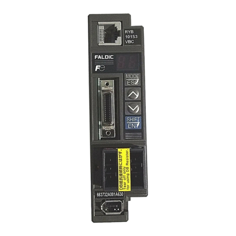
FujiFilm ALPHA 5 RYT-SX User manual

MEHT301a
FUJI SERVO SYSTEM
USER'S MANUAL
RYT-SX type

ii
This manual is "User's Manual for Fuji AC Servo System ALPHA5 Series".
The user's manual is in one volume and covers all handling methods of the product.
The following documents are included in the package of each device.
Device Document name Doc. No.
Servomotor Operation Manual
Fuji AC servomotor (GYSeries) ING-SI47-0863-JE
Servo amplifier
Operation manual
Fuji AC servo ALPHA5 Series
servo amplifier (RYTD (C/B)-□□□)
INR-SI47-1126-JE
The target model of this manual is shown below.
Device Model
Servomotor GYSD5-*** or GYCD5-*** or GYGC (B) 5-***
Servo amplifier RYTD (C/B)-VV□
* "" in the model indicates a decimal point or number.
* "*" in the model indicates an alphabet or blank.
For uncertainties in the product or description given in this manual, contact the dealer or our sales
office shown at the end of this volume.
Manual
Description given in this manual may be inconsistent to the product due to improvements added to
the product. Description given in this manual is subject to change without notice.
Illustrations included in this manual show the servo amplifier or servomotor of a specific capacity
and they may be different from the appearance of the product you purchased.
This product is not designed or manufactured for use in devices or systems related to human lives.
To use this product for aeronautic devices, traffic controllers, space industry devices, nuclear reactor
controllers, medical devices or systems including those devices, contact our sales window.
To use the product for equipment in which failure of the product will be engaged with human lives or
serious material losses, install safety devices matching the equipment.
Icon
The following icons are used in the description of the manual when necessary.
Negligence of description shown with this sign will undermine the true performance of the
product.
Reference items helpful for operation and data entry of the servomotor or servo amplifier
are described.

iii
CHAPTER 0 INTRODUCTION 0
CHAPTER 1 INSTALLATION 1
CHAPTER 2 WIRING 2
CHAPTER 3 OPERATION 3
CHAPTER 4 PARAMETER 4
CHAPTER 5 SERVO ADJUSTMENT 5
CHAPTER 6 KEYPAD 6
CHAPTER 7 MAINTENANCE AND INSPECTION 7
CHAPTER 8 SPECIFICATIONS 8
CHAPTER 9 CHARACTERISTICS 9
CHAPTER 10 PERIPHERAL EQUIPMENT 10
CHAPTER 11 ABSOLUTE POSITION SYSTEM 11
CHAPTER 12 POSITIONING DATA 12
CHAPTER 13 PC LOADER 13
CHAPTER 14 APPENDIXES 14

iv
CHAPTER 0 INTRODUCTION 0-1
0.1 Safety Precautions ・・・・・・・・・・・・・・・・・・・・・・・・・・・・・・・・・・・・・・・・・・0-2
■Precautions on use・・・・・・・・・・・・・・・・・・・・・・・・・・・・・・・・・・・・・・・・・・・・・・・・・・・・・・・ 0-3
■Precautions on storage ・・・・・・・・・・・・・・・・・・・・・・・・・・・・・・・・・・・・・・・・・・・・・・・・・・・ 0-4
■Precautions on transportation・・・・・・・・・・・・・・・・・・・・・・・・・・・・・・・・・・・・・・・・・・・・・・ 0-4
■Precautions on installation ・・・・・・・・・・・・・・・・・・・・・・・・・・・・・・・・・・・・・・・・・・・・・・・・ 0-5
■Precautions on wiring・・・・・・・・・・・・・・・・・・・・・・・・・・・・・・・・・・・・・・・・・・・・・・・・・・・・・ 0-6
■Precautions on operation ・・・・・・・・・・・・・・・・・・・・・・・・・・・・・・・・・・・・・・・・・・・・・・・・・ 0-7
■General precautions・・・・・・・・・・・・・・・・・・・・・・・・・・・・・・・・・・・・・・・・・・・・・・・・・・・・・・ 0-8
■Harmonics suppression measures (for Japan) ・・・・・・・・・・・・・・・・・・・・・・・・・・・・・・・ 0-8
■Compliance with EU directives ・・・・・・・・・・・・・・・・・・・・・・・・・・・・・・・・・・・・・・・・・・・・・ 0-9
■Compliance with RoHS directive ・・・・・・・・・・・・・・・・・・・・・・・・・・・・・・・・・・・・・・・・・・・ 0-9
■Service life of EEPROM ・・・・・・・・・・・・・・・・・・・・・・・・・・・・・・・・・・・・・・・・・・・・・・・・・・ 0-9
■Compliance with EU Directives and UL/CSA Standard ・・・・・・・・・・・・・・・・・・・・・・・ 0-10
0.2 Outline of System ・・・・・・・・・・・・・・・・・・・・・・・・・・・・・・・・・・・・・・・・・ 0-11
0.2.1 Servomotor ・・・・・・・・・・・・・・・・・・・・・・・・・・・・・・・・・・・・・・・・・・・・・ 0-11
0.2.2 Servo Amplifier ・・・・・・・・・・・・・・・・・・・・・・・・・・・・・・・・・・・・・・・・・・ 0-12
0.3 Model Nomenclature ・・・・・・・・・・・・・・・・・・・・・・・・・・・・・・・・・・・・・・ 0-13
0.3.1 Servomotor ・・・・・・・・・・・・・・・・・・・・・・・・・・・・・・・・・・・・・・・・・・・・・ 0-13
0.3.2 Servo Amplifier ・・・・・・・・・・・・・・・・・・・・・・・・・・・・・・・・・・・・・・・・・・ 0-14
0.4 Combination between Servomotor and Servo Amplifier ・・・・・・ 0-15
0.4.1 SX Type ・・・・・・・・・・・・・・・・・・・・・・・・・・・・・・・・・・・・・・・・・・・・・・・・ 0-15
CHAPTER 1 INSTALLATION 1-1
1.1 Servomotor・・・・・・・・・・・・・・・・・・・・・・・・・・・・・・・・・・・・・・・・・・・・・・・・・1-2
1.1.1 Storage Environment ・・・・・・・・・・・・・・・・・・・・・・・・・・・・・・・・・・・・・・ 1-2
1.1.2 Operating Environment ・・・・・・・・・・・・・・・・・・・・・・・・・・・・・・・・・・・・ 1-2
1.1.3 Installing the Servomotor・・・・・・・・・・・・・・・・・・・・・・・・・・・・・・・・・・・ 1-3
1.1.4 Water Proof and Oil Proof Properties ・・・・・・・・・・・・・・・・・・・・・・・・ 1-3
1.1.5 Servomotor Handling Precautions ・・・・・・・・・・・・・・・・・・・・・・・・・・・ 1-4
1.1.6 Notes on Stress Given to Cable ・・・・・・・・・・・・・・・・・・・・・・・・・・・・・ 1-4
1.1.7 Assembling Accuracy・・・・・・・・・・・・・・・・・・・・・・・・・・・・・・・・・・・・・・ 1-5
1.1.8 Allowable Load ・・・・・・・・・・・・・・・・・・・・・・・・・・・・・・・・・・・・・・・・・・・ 1-6
1.1.9 Cautionary Items on Servomotor Equipped with a Brake ・・・・・・・ 1-7
1.2 Servo Amplifier ・・・・・・・・・・・・・・・・・・・・・・・・・・・・・・・・・・・・・・・・・・・・・1-8
1.2.1 Storage Environment ・・・・・・・・・・・・・・・・・・・・・・・・・・・・・・・・・・・・・・ 1-8
Contents

v
1.2.2 Operating Environment ・・・・・・・・・・・・・・・・・・・・・・・・・・・・・・・・・・・・ 1-8
1.2.3 Installing the Servo Amplifier ・・・・・・・・・・・・・・・・・・・・・・・・・・・・・・・ 1-9
1.2.4 Depth of Control Panel・・・・・・・・・・・・・・・・・・・・・・・・・・・・・・・・・・・・ 1-10
CHAPTER 2 WIRING 2-1
2.1 Configuration ・・・・・・・・・・・・・・・・・・・・・・・・・・・・・・・・・・・・・・・・・・・・・・・2-2
2.1.1 Part Name ・・・・・・・・・・・・・・・・・・・・・・・・・・・・・・・・・・・・・・・・・・・・・・・ 2-2
2.1.2 Configuration ・・・・・・・・・・・・・・・・・・・・・・・・・・・・・・・・・・・・・・・・・・・・・ 2-5
2.1.3 Sequence I/O・・・・・・・・・・・・・・・・・・・・・・・・・・・・・・・・・・・・・・・・・・・・ 2-12
2.1.3.1 Pulse Input (PPI, CA, *CA, CB, *CA) ・・・・・・・・・・・・・・・・・・・・・・・・・・・・・・・・・ 2-14
2.1.3.2 Pulse Output (FFA, *FFA, FFB, *FFB, FFZ, *FFZ) ・・・・・・・・・・・・・・・・・・・・・・ 2-15
2.1.3.3 Z-Phase Output (FZ, M5) ・・・・・・・・・・・・・・・・・・・・・・・・・・・・・・・・・・・・・・・・・・・ 2-15
2.1.3.4 Analog Monitor Output (MON1, MON2, M5) ・・・・・・・・・・・・・・・・・・・・・・・・・・・ 2-15
2.1.3.5 Sequence Input (CONT1, CONT2, CONT3, ... COMIN) ・・・・・・・・・・・・・・・・・ 2-16
2.1.3.6 Sequence Output (OUT1, OUT2, ... COMOUT) ・・・・・・・・・・・・・・・・・・・・・・・・ 2-16
2.1.4 SX Bus (CN3) ・・・・・・・・・・・・・・・・・・・・・・・・・・・・・・・・・・・・・・・・・・・ 2-16
2.1.5 USB (CN4) ・・・・・・・・・・・・・・・・・・・・・・・・・・・・・・・・・・・・・・・・・・・・・・ 2-22
2.2 P-N Junction・・・・・・・・・・・・・・・・・・・・・・・・・・・・・・・・・・・・・・・・・・・・・・ 2-23
2.3 Servomotor・・・・・・・・・・・・・・・・・・・・・・・・・・・・・・・・・・・・・・・・・・・・・・・ 2-24
2.3.1 Brake Connector ・・・・・・・・・・・・・・・・・・・・・・・・・・・・・・・・・・・・・・・・・ 2-24
2.4 Encoder ・・・・・・・・・・・・・・・・・・・・・・・・・・・・・・・・・・・・・・・・・・・・・・・・・・ 2-25
2.4.1 Encoder Wiring Cable ・・・・・・・・・・・・・・・・・・・・・・・・・・・・・・・・・・・・ 2-25
2.4.2 Encoder Cable・・・・・・・・・・・・・・・・・・・・・・・・・・・・・・・・・・・・・・・・・・・ 2-26
2.5 Description of I/O Signals・・・・・・・・・・・・・・・・・・・・・・・・・・・・・・・・・・ 2-27
2.5.1 I/O Signals of VS Type・・・・・・・・・・・・・・・・・・・・・・・・・・・・・・・・・・・・ 2-27
List of input signals・・・・・・・・・・・・・・・・・・・・・・・・・・・・・・・・・・・・・・・・・・・・・・・・・・・・・・・・・ 2-27
List of output signals ・・・・・・・・・・・・・・・・・・・・・・・・・・・・・・・・・・・・・・・・・・・・・・・・・・・・・・・ 2-28
2.5.2 I/O Signals of LS Type・・・・・・・・・・・・・・・・・・・・・・・・・・・・・・・・・・・・ 2-29
List of input signals・・・・・・・・・・・・・・・・・・・・・・・・・・・・・・・・・・・・・・・・・・・・・・・・・・・・・・・・・ 2-29
List of output signals ・・・・・・・・・・・・・・・・・・・・・・・・・・・・・・・・・・・・・・・・・・・・・・・・・・・・・・・ 2-32
2.5.3 Signal Descriptions・・・・・・・・・・・・・・・・・・・・・・・・・・・・・・・・・・・・・・・ 2-34
Input signal ・・・・・・・・・・・・・・・・・・・・・・・・・・・・・・・・・・・・・・・・・・・・・・・・・・・・・・・・・・・・・・・ 2-34
Servo-on [S-ON]: Sequence input signal (Reference value 1)・・・・・・・・・・・・・・・・・・ 2-34
Forward command [FWD]: Sequence input signal (Reference value 2)・・・・・・・・・・ 2-34
Reverse command [REV]: Sequence input signal (Reference value 3) ・・・・・・・・・・ 2-34
Start positioning [START]: Sequence input signal (Reference value 4) ・・・・・・・・・・ 2-36
Homing [ORG]: Sequence input signal (Reference value 5) ・・・・・・・・・・・・・・・・・・・ 2-38
Homing position LS [LS]: Sequence input signal (Reference value 6) ・・・・・・・・・・・ 2-38

vi
Interrupt input: Sequence input signal (Reference value 49) ・・・・・・・・・・・・・・・・・・・ 2-38
Over-travel in positive direction [+OT]: Sequence input signal
(Reference value 7)・・・・・・・・・・・・・・・・・・・・・・・・・・・・・・・・・・・・・・・・・・・・・・・・・・・・・・ 2-40
Over-travel in negative direction [-OT]: Sequence input signal
(Reference value 8)・・・・・・・・・・・・・・・・・・・・・・・・・・・・・・・・・・・・・・・・・・・・・・・・・・・・・・ 2-40
ABS/INC: Sequence input signal (Reference value 9) ・・・・・・・・・・・・・・・・・・・・・・・・ 2-42
Forced stop [EMG]: Sequence input signal (Reference value 10)・・・・・・・・・・・・・・・ 2-43
Alarm reset [RST]: Sequence input signal (Reference value 11)・・・・・・・・・・・・・・・・ 2-44
VEL0: Sequence input signal (Reference value 12) ・・・・・・・・・・・・・・・・・・・・・・・・・・ 2-44
VEL1: Sequence input signal (Reference value 13) ・・・・・・・・・・・・・・・・・・・・・・・・・・ 2-44
ACC0: Sequence input signal (Reference value 14) ・・・・・・・・・・・・・・・・・・・・・・・・・・ 2-45
Position preset: Sequence input signal (Reference value 16) ・・・・・・・・・・・・・・・・・・ 2-46
Gain swtich: Sequence input signal (Reference value 17) ・・・・・・・・・・・・・・・・・・・・・ 2-46
Torque limit 0: Sequence input signal (Reference value 19) ・・・・・・・・・・・・・・・・・・・ 2-47
Torque limit 1: Sequence input signal (Reference value 20) ・・・・・・・・・・・・・・・・・・・ 2-47
Immediate value continuation: Sequence input signal (Reference value 22) ・・・・・ 2-49
Immediate value change: Sequence input signal (Reference value 23)・・・・・・・・・・ 2-51
Command pulse ratio 1: Sequence input signal (Reference value 27) ・・・・・・・・・・・ 2-52
Command pulse ratio 2: Sequence input signal (Reference value 28) ・・・・・・・・・・・ 2-52
Proportional control: Sequence input signal (Reference value 29) ・・・・・・・・・・・・・・ 2-53
Pause: Sequence input signal (Reference value 31)・・・・・・・・・・・・・・・・・・・・・・・・・・ 2-53
Positioning cancel: Sequence input signal (Reference value 32) ・・・・・・・・・・・・・・・ 2-54
External braking resistor overheat: Sequence input signal
(Reference value 34) ・・・・・・・・・・・・・・・・・・・・・・・・・・・・・・・・・・・・・・・・・・・・・・・・・・・・ 2-54
Teaching: Sequence input signal (Reference value 35) ・・・・・・・・・・・・・・・・・・・・・・・ 2-55
Torque control: Sequence input signal (Reference value - )・・・・・・・・・・・・・・・・・・・・ 2-56
Override enable: Sequence input signal (Reference value 43) ・・・・・・・・・・・・・・・・・ 2-57
Override 1: Sequence input signal (Reference value 44) ・・・・・・・・・・・・・・・・・・・・・・ 2-57
Override 2: Sequence input signal (Reference value 45) ・・・・・・・・・・・・・・・・・・・・・・ 2-57
Override 4: Sequence input signal (Reference value 46) ・・・・・・・・・・・・・・・・・・・・・・ 2-57
Override 8: Sequence input signal (Reference value 47) ・・・・・・・・・・・・・・・・・・・・・・ 2-57
Interrupt input enable: Sequence input signal (Reference value 48)・・・・・・・・・・・・・ 2-58
Interrupt input: Sequence input signal (Reference value 49) ・・・・・・・・・・・・・・・・・・・ 2-58
Interrupt position detection: Sequence input signal (Reference value -) ・・・・・・・・・ 2-58
Deviation clear: Sequence input signal (Reference value 50) ・・・・・・・・・・・・・・・・・・ 2-60
Multi-step speed selection [X1]: Sequence input signal (Reference value 51) ・・・・ 2-61
Multi-step speed selection [X2]: Sequence input signal (Reference value 52) ・・・・ 2-61
Multi-step speed selection [X3]: Sequence input signal (Reference value 53) ・・・・ 2-61

vii
Free-run [BX]: Sequence input signal (Reference value 54) ・・・・・・・・・・・・・・・・・・・ 2-61
Edit permission: Sequence input signal (Reference value 55)・・・・・・・・・・・・・・・・・・ 2-62
Anti resonance frequency selection 0: Sequence input signal
(Reference value 57) ・・・・・・・・・・・・・・・・・・・・・・・・・・・・・・・・・・・・・・・・・・・・・・・・・・・・ 2-63
Anti resonance frequency selection 1: Sequence input signal
(Reference value 58) ・・・・・・・・・・・・・・・・・・・・・・・・・・・・・・・・・・・・・・・・・・・・・・・・・・・・ 2-63
Toggle monitor 0: Sequence input signal (Reference value 75) ・・・・・・・・・・・・・・・・ 2-64
Toggle monitor 1: Sequence input signal (Reference value 76) ・・・・・・・・・・・・・・・・ 2-64
Position control: Sequence input signal (Reference value -) ・・・・・・・・・・・・・・・・・・・ 2-65
Position command operation: Sequence input signal (Reference value -)・・・・・・・・ 2-65
Z-phase detection command: Sequence input signal (Reference value -)・・・・・・・・ 2-66
SEL0:Sequence input signal (Reference value -) ・・・・・・・・・・・・・・・・・・・・・・・・・・・ 2-66
SEL1:Sequence input signal (Reference value -) ・・・・・・・・・・・・・・・・・・・・・・・・・・・ 2-66
SEL2:Sequence input signal (Reference value -) ・・・・・・・・・・・・・・・・・・・・・・・・・・・ 2-66
SEL3:Sequence input signal (Reference value -) ・・・・・・・・・・・・・・・・・・・・・・・・・・・ 2-66
Output signal ・・・・・・・・・・・・・・・・・・・・・・・・・・・・・・・・・・・・・・・・・・・・・・・・・・・・・・・・・・・・・・ 2-67
Ready for servo-on [RDY]: Sequence output signal (Reference value 1) ・・・・・・・・ 2-67
In-position [INP]: Sequence output signal (Reference value 2) ・・・・・・・・・・・・・・・・・ 2-68
Speed limit detection: Sequence output signal (Reference value 11)・・・・・・・・・・・・ 2-70
Over write completion: Sequence output signal (Reference value 13) ・・・・・・・・・・・ 2-70
Read completion: Sequence output signal (Reference value -)・・・・・・・・・・・・・・・・・ 2-70
Write command: Sequence input signal (Reference value -) ・・・・・・・・・・・・・・・・・・・ 2-70
Read command: Sequence input signal (Reference value -) ・・・・・・・・・・・・・・・・・・・ 2-70
Brake timing: Sequence output signal (Reference value 14) ・・・・・・・・・・・・・・・・・・・ 2-73
Alarm detection (normally open contact): Sequence output signal
(Reference value 16) ・・・・・・・・・・・・・・・・・・・・・・・・・・・・・・・・・・・・・・・・・・・・・・・・・・・・ 2-75
Alarm detection (normally closed contact): Sequence output signal
(Reference value 76) ・・・・・・・・・・・・・・・・・・・・・・・・・・・・・・・・・・・・・・・・・・・・・・・・・・・・ 2-75
Point detection, area detection 1: Sequence output signal
(Reference value 17) ・・・・・・・・・・・・・・・・・・・・・・・・・・・・・・・・・・・・・・・・・・・・・・・・・・・・ 2-76
Point detection, area detection 2: Sequence output signal
(Reference value 18) ・・・・・・・・・・・・・・・・・・・・・・・・・・・・・・・・・・・・・・・・・・・・・・・・・・・・ 2-76
Limiter detection: Sequence output signal (Reference value 19)・・・・・・・・・・・・・・・・ 2-77
OT detection: Sequence output signal (Reference value 20)・・・・・・・・・・・・・・・・・・・ 2-78
Cycle end detection: Sequence output signal (Reference value 21)・・・・・・・・・・・・・ 2-79
Homing completion: Sequence output signal (Reference value 22) ・・・・・・・・・・・・・ 2-80
Zero deviation: Sequence output signal (Reference value 23)・・・・・・・・・・・・・・・・・・ 2-81
Zero speed [NZERO]: Sequence output signal (Reference value 24) ・・・・・・・・・・・ 2-81

viii
Speed coincidence [NARV]: Sequence output signal (Reference value 25) ・・・・・・ 2-81
Torque limit detection: Sequence output signal (Reference value 26) ・・・・・・・・・・・ 2-82
Overload warning detection: Sequence output signal (Reference value 27) ・・・・・・ 2-82
Servo control ready [S-RDY]: Sequence output signal (Reference value 28) ・・・・・ 2-84
Edit permission response: Sequence output signal (Reference value 29) ・・・・・・・・ 2-84
Data error: Sequence output signal (Reference value 30) ・・・・・・・・・・・・・・・・・・・・・ 2-85
Address error: Sequence output signal (Reference value 31) ・・・・・・・・・・・・・・・・・・ 2-85
Alarm code 0: Sequence output signal (Reference value 32) ・・・・・・・・・・・・・・・・・・ 2-86
Alarm code 1: Sequence output signal (Reference value 33) ・・・・・・・・・・・・・・・・・・ 2-86
Alarm code 2: Sequence output signal (Reference value 34) ・・・・・・・・・・・・・・・・・・ 2-86
Alarm code 3: Sequence output signal (Reference value 35) ・・・・・・・・・・・・・・・・・・ 2-86
Alarm code 4: Sequence output signal (Reference value 36) ・・・・・・・・・・・・・・・・・・ 2-86
+OT detection: Sequence output signal (Reference value 38)・・・・・・・・・・・・・・・・・・ 2-88
-OT detection: Sequence output signal (Reference value 39) ・・・・・・・・・・・・・・・・・・ 2-88
Home position LS detection: Sequence output signal (Reference value 40) ・・・・・・ 2-89
Forced stop detection: Sequence output signal (Reference value 41) ・・・・・・・・・・・ 2-89
Toggle answer 0: Sequence output signal (Reference value 42) ・・・・・・・・・・・・・・・ 2-89
Toggle answer 1: Sequence output signal (Reference value 43) ・・・・・・・・・・・・・・・ 2-89
Toggle error: Sequence output signal (Reference value 44) ・・・・・・・・・・・・・・・・・・・ 2-89
Battery warning: Sequence output signal (Reference value 45) ・・・・・・・・・・・・・・・・ 2-89
Life warning: Sequence output signal (Reference value 46) ・・・・・・・・・・・・・・・・・・・ 2-90
MD0: Sequence output signal (Reference value 60) ・・・・・・・・・・・・・・・・・・・・・・・・・・ 2-90
MD1: Sequence output signal (Reference value 61) ・・・・・・・・・・・・・・・・・・・・・・・・・・ 2-90
MD2: Sequence output signal (Reference value 62) ・・・・・・・・・・・・・・・・・・・・・・・・・・ 2-90
MD3: Sequence output signal (Reference value 63) ・・・・・・・・・・・・・・・・・・・・・・・・・・ 2-90
MD4: Sequence output signal (Reference value 64) ・・・・・・・・・・・・・・・・・・・・・・・・・・ 2-90
MD5: Sequence output signal (Reference value 65) ・・・・・・・・・・・・・・・・・・・・・・・・・・ 2-90
MD6: Sequence output signal (Reference value 66) ・・・・・・・・・・・・・・・・・・・・・・・・・・ 2-90
MD7: Sequence output signal (Reference value 67) ・・・・・・・・・・・・・・・・・・・・・・・・・・ 2-90
Position preset completion: Sequence output signal (Reference value 75) ・・・・・・・ 2-92
Immediate value continuation permission: Sequence output signal
(Reference value 79) ・・・・・・・・・・・・・・・・・・・・・・・・・・・・・・・・・・・・・・・・・・・・・・・・・・・・ 2-93
Immediate value continuation completion: Sequence output signal
(Reference value 80) ・・・・・・・・・・・・・・・・・・・・・・・・・・・・・・・・・・・・・・・・・・・・・・・・・・・・ 2-93
Immediate value change completion: Sequence output signal
(Reference value 81) ・・・・・・・・・・・・・・・・・・・・・・・・・・・・・・・・・・・・・・・・・・・・・・・・・・・・ 2-94
Command positioning completion: Sequence output signal
(Reference value 82) ・・・・・・・・・・・・・・・・・・・・・・・・・・・・・・・・・・・・・・・・・・・・・・・・・・・・ 2-94

ix
CONTa Through: Sequence output signal (Reference value 91) ・・・・・・・・・・・・・・・ 2-96
CONTb Through: Sequence output signal (Reference value 92) ・・・・・・・・・・・・・・・ 2-96
CONT1 Through: Sequence output signal (Reference value -) ・・・・・・・・・・・・・・・・・ 2-96
CONT2 Through: Sequence output signal (Reference value -) ・・・・・・・・・・・・・・・・・ 2-96
CONT3 Through: Sequence output signal (Reference value -) ・・・・・・・・・・・・・・・・・ 2-96
CONT4 Through: Sequence output signal (Reference value -) ・・・・・・・・・・・・・・・・・ 2-96
CONT5 Through: Sequence output signal (Reference value -) ・・・・・・・・・・・・・・・・・ 2-96
Internal command pulse zero: Sequence output signal (Reference value -) ・・・・・・ 2-97
Z-phase detection: Sequence output signal (Reference value -)・・・・・・・・・・・・・・・・ 2-97
Deviation overflow: Sequence output signal (Reference value -) ・・・・・・・・・・・・・・・ 2-97
Interrupt position detection: Sequence output signal (Reference value -) ・・・・・・・・ 2-97
CSEL0: Sequence output signal (Reference value -) ・・・・・・・・・・・・・・・・・・・・・・・・・ 2-97
CSEL1: Sequence output signal (Reference value -) ・・・・・・・・・・・・・・・・・・・・・・・・・ 2-97
CSEL2: Sequence output signal (Reference value -) ・・・・・・・・・・・・・・・・・・・・・・・・・ 2-97
CHAPTER 3 OPERATION 3-1
3.1 Signal Description (Priority among Input Signals)・・・・・・・・・・・・・・3-2
3.2 Operation Check ・・・・・・・・・・・・・・・・・・・・・・・・・・・・・・・・・・・・・・・・・・・・3-3
3.2.1 Power-On・・・・・・・・・・・・・・・・・・・・・・・・・・・・・・・・・・・・・・・・・・・・・・・・ 3-3
3.2.2 Power-On/Servo Control-Ready [S-RDY]・・・・・・・・・・・・・・・・・・・・・ 3-4
3.2.3 Servo-On [S-ON]/Ready for Servo-On [RDY] ・・・・・・・・・・・・・・・・・ 3-4
3.2.4 Test Operation at Keypad ・・・・・・・・・・・・・・・・・・・・・・・・・・・・・・・・・・ 3-5
3.2.5 If the Servomotor Fails to Start・・・・・・・・・・・・・・・・・・・・・・・・・・・・・・ 3-6
3.2.6 Shutdown ・・・・・・・・・・・・・・・・・・・・・・・・・・・・・・・・・・・・・・・・・・・・・・・・ 3-6
3.3 Operation with VS Type・・・・・・・・・・・・・・・・・・・・・・・・・・・・・・・・・・・・・・3-7
3.3.1 IQ Area ・・・・・・・・・・・・・・・・・・・・・・・・・・・・・・・・・・・・・・・・・・・・・・・・・・ 3-7
3.3.2 Servo-On [S-ON]/ Ready for Servo-on [RDY] ・・・・・・・・・・・・・・・・・ 3-8
3.3.3 Switching among Position Control, Speed Control and
Torque Control ・・・・・・・・・・・・・・・・・・・・・・・・・・・・・・・・・・・・・・・・・・・ 3-8
3.3.4 Operation under Position Control・・・・・・・・・・・・・・・・・・・・・・・・・・・・ 3-8
3.3.5 Operation under Speed Control ・・・・・・・・・・・・・・・・・・・・・・・・・・・・ 3-10
3.3.6 Operation under Torque Control ・・・・・・・・・・・・・・・・・・・・・・・・・・・ 3-10
3.3.7 Interrupting/Stopping Operation ・・・・・・・・・・・・・・・・・・・・・・・・・・・・ 3-11
3.3.8 Writing a Parameter ・・・・・・・・・・・・・・・・・・・・・・・・・・・・・・・・・・・・・・ 3-16
3.3.9 Selecting the Monitor ・・・・・・・・・・・・・・・・・・・・・・・・・・・・・・・・・・・・・ 3-20
3.4 Operation with LS Type・・・・・・・・・・・・・・・・・・・・・・・・・・・・・・・・・・・・ 3-22
3.4.1 IQ Area ・・・・・・・・・・・・・・・・・・・・・・・・・・・・・・・・・・・・・・・・・・・・・・・・・ 3-22
3.4.2 Immediate data operation ・・・・・・・・・・・・・・・・・・・・・・・・・・・・・・・・・ 3-31

x
3.4.3 Positioning Data Operation ・・・・・・・・・・・・・・・・・・・・・・・・・・・・・・・・ 3-35
3.4.4 Pulse Operation ・・・・・・・・・・・・・・・・・・・・・・・・・・・・・・・・・・・・・・・・・ 3-37
3.4.5 Interrupting/Stopping Operation ・・・・・・・・・・・・・・・・・・・・・・・・・・・・ 3-38
3.4.6 Reading/writing a Parameter ・・・・・・・・・・・・・・・・・・・・・・・・・・・・・・ 3-46
3.4.7 Reading/writing a Positioning Data ・・・・・・・・・・・・・・・・・・・・・・・・・ 3-49
3.4.8 Selecting the Monitor ・・・・・・・・・・・・・・・・・・・・・・・・・・・・・・・・・・・・・ 3-53
CHAPTER 4 PARAMETER 4-1
4.1 Parameter Division ・・・・・・・・・・・・・・・・・・・・・・・・・・・・・・・・・・・・・・・・・・4-2
4.2 Basic Parameters ・・・・・・・・・・・・・・・・・・・・・・・・・・・・・・・・・・・・・・・・・・・4-2
4.2.1 List (PA1_)・・・・・・・・・・・・・・・・・・・・・・・・・・・・・・・・・・・・・・・・・・・ 4-2
4.2.2 Description of Each Parameter・・・・・・・・・・・・・・・・・・・・・・・・・・・・・・ 4-4
PA1_02 INC/ABS system selection・・・・・・・・・・・・・・・・・・・・・・・・・・・・・・・・・・・・・・・・ 4-4
PA1_03 Command pulse form selection・・・・・・・・・・・・・・・・・・・・・・・・・・・・・・・・・・・・ 4-4
PA1_04 Rotation direction selection ・・・・・・・・・・・・・・・・・・・・・・・・・・・・・・・・・・・・・・・ 4-6
PA1_05 Number of command input pulses per revolution・・・・・・・・・・・・・・・・・・・・・ 4-7
PA1_06 Numerator 0 of electronic gear,
PA1_07 Denominator of electronic gear・・・・・・・・・・・・・・・・・・・・・・・・・・・・・・・・・・・・ 4-7
PA1_08 Number of output pulses per revolution・・・・・・・・・・・・・・・・・・・・・・・・・・・・・ 4-9
PA1_09 Numerator of electric gear for output pulses・・・・・・・・・・・・・・・・・・・・・・・・・ 4-9
PA1_10 Denominator of electric gear for output pulses・・・・・・・・・・・・・・・・・・・・・・・ 4-9
PA1_11 Output pulse phase selection at CCW rotation・・・・・・・・・・・・・・・・・・・・・・ 4-10
PA1_12 Z-phase position offset・・・・・・・・・・・・・・・・・・・・・・・・・・・・・・・・・・・・・・・・・・ 4-10
PA1_13 Tuning mode selection ・・・・・・・・・・・・・・・・・・・・・・・・・・・・・・・・・・・・・・・・・・ 4-11
PA1_14 Load inertia ratio ・・・・・・・・・・・・・・・・・・・・・・・・・・・・・・・・・・・・・・・・・・・・・・・ 4-12
PA1_15 Auto tuning gain 1 ・・・・・・・・・・・・・・・・・・・・・・・・・・・・・・・・・・・・・・・・・・・・・・ 4-13
PA1_16 Auto tuning gain 2 ・・・・・・・・・・・・・・・・・・・・・・・・・・・・・・・・・・・・・・・・・・・・・・ 4-14
PA1_20 to 23 Easy tuning settings ・・・・・・・・・・・・・・・・・・・・・・・・・・・・・・・・・・・・・・・ 4-15
PA1_25 Max. rotation speed (for position and speed control)・・・・・・・・・・・・・・・・・ 4-15
PA1_26 Max. rotation speed (for torque control)・・・・・・・・・・・・・・・・・・・・・・・・・・・・ 4-15
PA1_27 Forward rotation torque limit ・・・・・・・・・・・・・・・・・・・・・・・・・・・・・・・・・・・・・ 4-15
PA1_28 Reverse rotation torque limit ・・・・・・・・・・・・・・・・・・・・・・・・・・・・・・・・・・・・・ 4-15
PA1_29 Speed coincidence range ・・・・・・・・・・・・・・・・・・・・・・・・・・・・・・・・・・・・・・・ 4-16
PA1_30 Zero speed range ・・・・・・・・・・・・・・・・・・・・・・・・・・・・・・・・・・・・・・・・・・・・・・ 4-16
PA1_31 Deviation unit selection ・・・・・・・・・・・・・・・・・・・・・・・・・・・・・・・・・・・・・・・・・ 4-17
PA1_32 Zero deviation range/In-position range ・・・・・・・・・・・・・・・・・・・・・・・・・・・・ 4-17
PA1_33 to 35 In-position output signals ・・・・・・・・・・・・・・・・・・・・・・・・・・・・・・・・・・・ 4-17

xi
PA1_36 to 40 Acceleration / deceleration selection at speed control,
Acceleration time and deceleration time settings・・・・・・・・・・・・・・・ 4-19
PA1_41 to 47 Manual feed speed 1 to 7 ・・・・・・・・・・・・・・・・・・・・・・・・・・・・・・・・・・ 4-21
4.3 Control Gain and Filter Setting Parameters・・・・・・・・・・・・・・・・・・ 4-22
4.3.1 List (PA1_)・・・・・・・・・・・・・・・・・・・・・・・・・・・・・・・・・・・・・・・・・・ 4-22
4.3.2 Description of Each Parameter・・・・・・・・・・・・・・・・・・・・・・・・・・・・・ 4-23
PA1_51 to 53 Command filter settings ・・・・・・・・・・・・・・・・・・・・・・・・・・・・・・・・・・・・ 4-23
PA1_54 Position command response time constant ・・・・・・・・・・・・・・・・・・・・・・・・ 4-24
PA1_55 to 57 Response to disturbance settings・・・・・・・・・・・・・・・・・・・・・・・・・・・・ 4-24
PA1_58 Feed forward gain 1 ・・・・・・・・・・・・・・・・・・・・・・・・・・・・・・・・・・・・・・・・・・・・ 4-25
PA1_59 Torque filter time constant for position and speed control
PA1_60 Torque filter time constant for torque control ・・・・・・・・・・・・・・・・・・・・・・・ 4-25
PA1_61 to 67 Second gain settings ・・・・・・・・・・・・・・・・・・・・・・・・・・・・・・・・・・・・・・ 4-26
PA1_68 Acceleration compensation gain for position control ・・・・・・・・・・・・・・・・・ 4-27
PA1_70 to 76 Notch filter settings ・・・・・・・・・・・・・・・・・・・・・・・・・・・・・・・・・・・・・・・・ 4-27
PA1_77 to 86 Vibration suppressing control settings ・・・・・・・・・・・・・・・・・・・・・・・・ 4-29
PA1_87 Model torque filter time constant・・・・・・・・・・・・・・・・・・・・・・・・・・・・・・・・・・ 4-30
PA1_88 Position loop integration time constant
PA1_89 Position loop integration limiter ・・・・・・・・・・・・・・・・・・・・・・・・・・・・・・・・・・・ 4-30
PA1_90 Load torque observer ・・・・・・・・・・・・・・・・・・・・・・・・・・・・・・・・・・・・・・・・・・・ 4-30
PA1_91 P/PI automatic change selection・・・・・・・・・・・・・・・・・・・・・・・・・・・・・・・・・・ 4-30
PA1_92 and 93 Friction compensation settings ・・・・・・・・・・・・・・・・・・・・・・・・・・・・ 4-31
PA1_94 Torque filter setting mode ・・・・・・・・・・・・・・・・・・・・・・・・・・・・・・・・・・・・・・・ 4-31
PA1_95 Model torque calculation selection, speed observer selection ・・・・・・・・・ 4-31
PA1_96 Speed limit gain for torque control ・・・・・・・・・・・・・・・・・・・・・・・・・・・・・・・・ 4-32
4.4 Automatic Operation Setting Parameters・・・・・・・・・・・・・・・・・・・・ 4-33
4.4.1 List (PA2_)・・・・・・・・・・・・・・・・・・・・・・・・・・・・・・・・・・・・・・・・・・ 4-33
4.4.2 Description of Each Parameter・・・・・・・・・・・・・・・・・・・・・・・・・・・・・ 4-34
PA2_01 Decimal point position of positioning data ・・・・・・・・・・・・・・・・・・・・・・・・・・ 4-34
PA2_02 to 05 Positioning speed 1 to 4・・・・・・・・・・・・・・・・・・・・・・・・・・・・・・・・・・・・ 4-34
PA2_06 to 18 and 24 Homing settings ・・・・・・・・・・・・・・・・・・・・・・・・・・・・・・・・・・・・ 4-35
PA2_06 Homing speed ・・・・・・・・・・・・・・・・・・・・・・・・・・・・・・・・・・・・・・・・・・・・・・・・・ 4-37
PA2_07 Creep speed for homing・・・・・・・・・・・・・・・・・・・・・・・・・・・・・・・・・・・・・・・・・ 4-37
PA2_08 Starting direction for homing ・・・・・・・・・・・・・・・・・・・・・・・・・・・・・・・・・・・・・ 4-37
PA2_09 Reverse traveling unit amount for homing・・・・・・・・・・・・・・・・・・・・・・・・・・ 4-38
PA2_10 Homing direction after reference signal detection ・・・・・・・・・・・・・・・・・・・ 4-39
PA2_11 Reference signal for shift operation ・・・・・・・・・・・・・・・・・・・・・・・・・・・・・・・ 4-39
PA2_12 Reference signal for homing (Deceleration starting signal) ・・・・・・・・・・・ 4-40

xii
PA2_13 Home position LS signal edge selection ・・・・・・・・・・・・・・・・・・・・・・・・・・・ 4-40
PA2_14 Home position shift unit amount ・・・・・・・・・・・・・・・・・・・・・・・・・・・・・・・・・・ 4-41
PA2_15 Deceleration operation for creep speed・・・・・・・・・・・・・・・・・・・・・・・・・・・・ 4-41
PA2_16 Home position after homing completion ・・・・・・・・・・・・・・・・・・・・・・・・・・・ 4-42
PA2_17 Home position detection range ・・・・・・・・・・・・・・・・・・・・・・・・・・・・・・・・・・・ 4-42
PA2_18 Deceleration time at OT during homing・・・・・・・・・・・・・・・・・・・・・・・・・・・・ 4-42
PA2_22 Detection time for contact-stopper
PA2_23 Torque limit for contact-stopper ・・・・・・・・・・・・・・・・・・・・・・・・・・・・・・・・・・ 4-43
PA2_24 Selection of operation at OT during homing ・・・・・・・・・・・・・・・・・・・・・・・・ 4-44
PA2_19 Preset position・・・・・・・・・・・・・・・・・・・・・・・・・・・・・・・・・・・・・・・・・・・・・・・・・ 4-66
PA2_20 Interrupt traveling unit amount ・・・・・・・・・・・・・・・・・・・・・・・・・・・・・・・・・・・ 4-66
PA2_25 to 27 Position operation type, software OT detection position ・・・・・・・・・ 4-66
PA2_28 and 29 Limiter detection position ・・・・・・・・・・・・・・・・・・・・・・・・・・・・・・・・・ 4-67
PA2_30 Backlash compensation ・・・・・・・・・・・・・・・・・・・・・・・・・・・・・・・・・・・・・・・・・ 4-67
PA2_31 to 34 Point detection, area detection settings・・・・・・・・・・・・・・・・・・・・・・・ 4-68
PA2_36 to 39 Override settings ・・・・・・・・・・・・・・・・・・・・・・・・・・・・・・・・・・・・・・・・・・ 4-70
PA2_40 Internal positioning data selection ・・・・・・・・・・・・・・・・・・・・・・・・・・・・・・・・ 4-70
PA2_41 Sequential start selection・・・・・・・・・・・・・・・・・・・・・・・・・・・・・・・・・・・・・・・・ 4-71
PA2_42 Decimal point position of stand still timer ・・・・・・・・・・・・・・・・・・・・・・・・・・ 4-71
PA2_43 Output selection at M code OFF・・・・・・・・・・・・・・・・・・・・・・・・・・・・・・・・・・ 4-71
4.5 Extended Function Setting Parameters ・・・・・・・・・・・・・・・・・・・・・ 4-72
4.5.1 List (PA2_)・・・・・・・・・・・・・・・・・・・・・・・・・・・・・・・・・・・・・・・・・・ 4-72
4.5.2 Description of Each Parameter・・・・・・・・・・・・・・・・・・・・・・・・・・・・・ 4-73
PA2_54 and 55 Command pulse ratio 1, 2・・・・・・・・・・・・・・・・・・・・・・・・・・・・・・・・・ 4-73
PA2_56 Speed limit selection at torque control・・・・・・・・・・・・・・・・・・・・・・・・・・・・・ 4-73
PA2_57 to 60 Torque limit settings ・・・・・・・・・・・・・・・・・・・・・・・・・・・・・・・・・・・・・・・ 4-74
PA2_61 to 63 Action sequence settings ・・・・・・・・・・・・・・・・・・・・・・・・・・・・・・・・・・・ 4-77
PA2_64 Torque keeping time to holding brake ・・・・・・・・・・・・・・・・・・・・・・・・・・・・・ 4-78
PA2_65 Braking resistor selection・・・・・・・・・・・・・・・・・・・・・・・・・・・・・・・・・・・・・・・・ 4-78
PA2_66 Flying start at speed control ・・・・・・・・・・・・・・・・・・・・・・・・・・・・・・・・・・・・・ 4-79
PA2_67 Alarm detection at undervoltage ・・・・・・・・・・・・・・・・・・・・・・・・・・・・・・・・・・ 4-79
PA2_68 Main power shutoff detection time ・・・・・・・・・・・・・・・・・・・・・・・・・・・・・・・・ 4-79
PA2_69 Deviation detection overflow value・・・・・・・・・・・・・・・・・・・・・・・・・・・・・・・・ 4-80
PA2_70 Overload warning value ・・・・・・・・・・・・・・・・・・・・・・・・・・・・・・・・・・・・・・・・・ 4-80
PA2_72 Station number for communications・・・・・・・・・・・・・・・・・・・・・・・・・・・・・・・ 4-80
PA2_74 Parameter write protection・・・・・・・・・・・・・・・・・・・・・・・・・・・・・・・・・・・・・・・ 4-80
PA2_75 Positioning data write protection・・・・・・・・・・・・・・・・・・・・・・・・・・・・・・・・・・ 4-80
PA2_77 Initial display of the keypad (Keypad) ・・・・・・・・・・・・・・・・・・・・・・・・・・・・・ 4-81

xiii
PA2_78 Display transition at warning detection ・・・・・・・・・・・・・・・・・・・・・・・・・・・・ 4-81
PA2_80 to 85 Parameter in RAM 1 to 6 ・・・・・・・・・・・・・・・・・・・・・・・・・・・・・・・・・・・ 4-82
PA2_86 to 88 Positioning data in RAM 1 to 3 ・・・・・・・・・・・・・・・・・・・・・・・・・・・・・・ 4-82
PA2_89 and 90 Sequence test mode: Mode selection and encoder selection・・・ 4-83
PA2_91 Position command delay time ・・・・・・・・・・・・・・・・・・・・・・・・・・・・・・・・・・・・ 4-83
PA2_92 SX extension function・・・・・・・・・・・・・・・・・・・・・・・・・・・・・・・・・・・・・・・・・・・ 4-84
4.6 Input Terminal Function Setting Parameters・・・・・・・・・・・・・・・・・ 4-85
4.6.1 List (PA3_)・・・・・・・・・・・・・・・・・・・・・・・・・・・・・・・・・・・・・・・・・・ 4-85
4.6.2 Description of Each Parameter・・・・・・・・・・・・・・・・・・・・・・・・・・・・・ 4-86
PA3_26 to 30 CONT always ON 1 to 5・・・・・・・・・・・・・・・・・・・・・・・・・・・・・・・・・・・・ 4-90
PA3_36 Deviation clear input form ・・・・・・・・・・・・・・・・・・・・・・・・・・・・・・・・・・・・・・・ 4-90
4.7 Output Terminal Function Setting Parameters ・・・・・・・・・・・・・・・ 4-91
4.7.1 List (PA3_)・・・・・・・・・・・・・・・・・・・・・・・・・・・・・・・・・・・・・・・・・・ 4-91
4.7.2 Description of Each Parameter・・・・・・・・・・・・・・・・・・・・・・・・・・・・・ 4-92
PA3_51 to 55 OUT 1 to 16 signal assignment・・・・・・・・・・・・・・・・・・・・・・・・・・・・・・ 4-92
PA3_81 to 87 Monitor output scale and offset settings ・・・・・・・・・・・・・・・・・・・・・・ 4-96
PA3_88 Command pulse frequency sampling time for monitor ・・・・・・・・・・・・・・・ 4-98
PA3_89 Feedback speed sampling time for monitor ・・・・・・・・・・・・・・・・・・・・・・・・ 4-99
CHAPTER 5 SERVO ADJUSTMENT 5-1
5.1 Adjustment Procedure・・・・・・・・・・・・・・・・・・・・・・・・・・・・・・・・・・・・・・・5-2
5.2 Easy Tuning ・・・・・・・・・・・・・・・・・・・・・・・・・・・・・・・・・・・・・・・・・・・・・・・・5-3
5.2.1 What is Easy Tuning? ・・・・・・・・・・・・・・・・・・・・・・・・・・・・・・・・・・・・・ 5-3
5.2.2 Easy Tuning Operation Profile ・・・・・・・・・・・・・・・・・・・・・・・・・・・・・・ 5-3
5.2.3 Description of Operation ・・・・・・・・・・・・・・・・・・・・・・・・・・・・・・・・・・・ 5-5
5.3 Auto Tuning ・・・・・・・・・・・・・・・・・・・・・・・・・・・・・・・・・・・・・・・・・・・・・・・・5-9
5.3.1 Conditions for Auto Tuning ・・・・・・・・・・・・・・・・・・・・・・・・・・・・・・・・・ 5-9
5.3.2 Parameters Used for Auto Tuning ・・・・・・・・・・・・・・・・・・・・・・・・・・・ 5-9
5.3.3 Approximate Reference Value of Auto Tuning Gain 1 ・・・・・・・・・ 5-10
5.3.4 Auto Tuning Adjustment Procedure・・・・・・・・・・・・・・・・・・・・・・・・・ 5-11
5.4 Auto Tuning Application ・・・・・・・・・・・・・・・・・・・・・・・・・・・・・・・・・・・ 5-12
5.4.1 Parameters Used for Auto Tuning Application・・・・・・・・・・・・・・・・ 5-12
5.4.2 Notch Filter Setting Method・・・・・・・・・・・・・・・・・・・・・・・・・・・・・・・・ 5-13
5.4.3 Adjustment Procedure with Auto Tuning Application ・・・・・・・・・・ 5-15
5.5 Manual Tuning ・・・・・・・・・・・・・・・・・・・・・・・・・・・・・・・・・・・・・・・・・・・・ 5-16
5.5.1 Conditions for Manual Tuning・・・・・・・・・・・・・・・・・・・・・・・・・・・・・・ 5-16
5.5.2 Parameters Used for Manual Tuning・・・・・・・・・・・・・・・・・・・・・・・・ 5-16
5.5.3 Approximate Gain Reference Value ・・・・・・・・・・・・・・・・・・・・・・・・ 5-16

xiv
5.5.4 Manual Tuning Adjustment Procedure ・・・・・・・・・・・・・・・・・・・・・・ 5-17
5.5.5 Individual Adjustment ・・・・・・・・・・・・・・・・・・・・・・・・・・・・・・・・・・・・・ 5-18
5.6 Interpolation Control Mode ・・・・・・・・・・・・・・・・・・・・・・・・・・・・・・・・ 5-19
5.6.1 Conditions for Interpolation Control Mode ・・・・・・・・・・・・・・・・・・・ 5-19
5.6.2 Parameters Used for Interpolation Control Mode ・・・・・・・・・・・・・ 5-19
5.6.3 Adjustment Procedure in Interpolation Control Mode・・・・・・・・・・ 5-20
5.7 Profile Operation・・・・・・・・・・・・・・・・・・・・・・・・・・・・・・・・・・・・・・・・・・ 5-21
5.7.1 What is Profile Operation? ・・・・・・・・・・・・・・・・・・・・・・・・・・・・・・・・ 5-21
5.7.2 Description of Operation ・・・・・・・・・・・・・・・・・・・・・・・・・・・・・・・・・・ 5-22
5.8 Special Adjustment (Vibration Suppression) ・・・・・・・・・・・・・・・・ 5-24
5.8.1 What is Vibration Suppression ? ・・・・・・・・・・・・・・・・・・・・・・・・・・・ 5-24
5.8.2 Automatic Vibration Suppression ・・・・・・・・・・・・・・・・・・・・・・・・・・・ 5-26
5.8.3 Manual Adjustment of Vibration Suppression ・・・・・・・・・・・・・・・・ 5-27
CHAPTER 6 KEYPAD 6-1
6.1 Display・・・・・・・・・・・・・・・・・・・・・・・・・・・・・・・・・・・・・・・・・・・・・・・・・・・・・6-2
6.1.1 Mode ・・・・・・・・・・・・・・・・・・・・・・・・・・・・・・・・・・・・・・・・・・・・・・・・・・・・ 6-2
6.1.2 Key ・・・・・・・・・・・・・・・・・・・・・・・・・・・・・・・・・・・・・・・・・・・・・・・・・・・・・ 6-3
6.1.3 Mode Selection ・・・・・・・・・・・・・・・・・・・・・・・・・・・・・・・・・・・・・・・・・・・ 6-3
6.2 Function List ・・・・・・・・・・・・・・・・・・・・・・・・・・・・・・・・・・・・・・・・・・・・・・・6-4
6.3 Sequence Mode・・・・・・・・・・・・・・・・・・・・・・・・・・・・・・・・・・・・・・・・・・・・・6-8
6.4 Monitor Mode ・・・・・・・・・・・・・・・・・・・・・・・・・・・・・・・・・・・・・・・・・・・・・ 6-12
6.5 Station No Mode ・・・・・・・・・・・・・・・・・・・・・・・・・・・・・・・・・・・・・・・・・・ 6-20
6.6 Maintenance Mode ・・・・・・・・・・・・・・・・・・・・・・・・・・・・・・・・・・・・・・・・ 6-21
6.7 Parameter Edit Mode ・・・・・・・・・・・・・・・・・・・・・・・・・・・・・・・・・・・・・・ 6-25
6.8 Positioning Data Edit Mode ・・・・・・・・・・・・・・・・・・・・・・・・・・・・・・・・ 6-29
6.9 Test Operation Mode ・・・・・・・・・・・・・・・・・・・・・・・・・・・・・・・・・・・・・・ 6-32
CHAPTER 7 MAINTENANCE AND INSPECTION 7-1
7.1 Inspection ・・・・・・・・・・・・・・・・・・・・・・・・・・・・・・・・・・・・・・・・・・・・・・・・・・7-2
7.2 Status Display ・・・・・・・・・・・・・・・・・・・・・・・・・・・・・・・・・・・・・・・・・・・・・・7-3
7.2.1 Initial State ・・・・・・・・・・・・・・・・・・・・・・・・・・・・・・・・・・・・・・・・・・・・・・・ 7-3
7.2.2 State at Alarm ・・・・・・・・・・・・・・・・・・・・・・・・・・・・・・・・・・・・・・・・・・・・ 7-3
7.2.3 Alarm Display List・・・・・・・・・・・・・・・・・・・・・・・・・・・・・・・・・・・・・・・・・ 7-4
7.3 Troubleshooting Method・・・・・・・・・・・・・・・・・・・・・・・・・・・・・・・・・・・・・7-6
7.4 Items to be Inquired upon Trouble ・・・・・・・・・・・・・・・・・・・・・・・・・・ 7-15
7.5 Maintenance and Discarding ・・・・・・・・・・・・・・・・・・・・・・・・・・・・・・・ 7-16
7.5.1 Operating Environment ・・・・・・・・・・・・・・・・・・・・・・・・・・・・・・・・・・・ 7-16
7.5.2 Life・・・・・・・・・・・・・・・・・・・・・・・・・・・・・・・・・・・・・・・・・・・・・・・・・・・・・ 7-17

xv
7.5.3 Discarding ・・・・・・・・・・・・・・・・・・・・・・・・・・・・・・・・・・・・・・・・・・・・・・ 7-17
7.6 Approximate Replacement Timing ・・・・・・・・・・・・・・・・・・・・・・・・・・ 7-18
CHAPTER 8 SPECIFICATIONS 8-1
8.1 Specifications of Servomotor ・・・・・・・・・・・・・・・・・・・・・・・・・・・・・・・・8-2
8.1.1 GYS Motor ・・・・・・・・・・・・・・・・・・・・・・・・・・・・・・・・・・・・・・・・・・・・・・・ 8-2
8.1.2 GYC Motor ・・・・・・・・・・・・・・・・・・・・・・・・・・・・・・・・・・・・・・・・・・・・・・・ 8-8
8.1.3 GYG Motor [2000 r/min]・・・・・・・・・・・・・・・・・・・・・・・・・・・・・・・・・・・ 8-10
8.1.4 GYG Motor [1500 r/min]・・・・・・・・・・・・・・・・・・・・・・・・・・・・・・・・・・・ 8-12
8.2 Specifications of Servo Amplifier ・・・・・・・・・・・・・・・・・・・・・・・・・・・ 8-14
8.2.1 Common Specifications ・・・・・・・・・・・・・・・・・・・・・・・・・・・・・・・・・・・ 8-14
8.2.2 Specifications of VV Type ・・・・・・・・・・・・・・・・・・・・・・・・・・・・・・・・・ 8-15
8.2.3 Specifications of VS Type ・・・・・・・・・・・・・・・・・・・・・・・・・・・・・・・・・ 8-16
8.2.4 Specifications of LS Type ・・・・・・・・・・・・・・・・・・・・・・・・・・・・・・・・・ 8-17
8.3 Dimensions of Servomotor ・・・・・・・・・・・・・・・・・・・・・・・・・・・・・・・・ 8-18
8.3.1 GYS Motor ・・・・・・・・・・・・・・・・・・・・・・・・・・・・・・・・・・・・・・・・・・・・・・ 8-18
8.3.2 GYS Motor (With a Brake)・・・・・・・・・・・・・・・・・・・・・・・・・・・・・・・・・ 8-19
8.3.3 GYC Motor ・・・・・・・・・・・・・・・・・・・・・・・・・・・・・・・・・・・・・・・・・・・・・・ 8-20
8.3.4 GYC Motor (With a brake)・・・・・・・・・・・・・・・・・・・・・・・・・・・・・・・・・ 8-21
8.3.5 GYG Motor (2000[r/min])・・・・・・・・・・・・・・・・・・・・・・・・・・・・・・・・・・ 8-22
8.3.6 GYG Motor (2000[r/min]) (With a brake) ・・・・・・・・・・・・・・・・・・・ 8-22
8.3.7 GYG Motor (1500[r/min])・・・・・・・・・・・・・・・・・・・・・・・・・・・・・・・・・・ 8-23
8.3.8 GYG Motor (1500[r/min]) (With a brake) ・・・・・・・・・・・・・・・・・・・ 8-23
8.4 Optional Specification of Shaft Extension
[With a Key, Tapped] ・・・・・・・・・・・・・・・・・・・・・・・・・・・・・・・・・・・・・・ 8-24
8.5 Dimensions of Servo Amplifier ・・・・・・・・・・・・・・・・・・・・・・・・・・・・・ 8-25
CHAPTER 9 CHARACTERISTICS 9-1
9.1 Timing Chart・・・・・・・・・・・・・・・・・・・・・・・・・・・・・・・・・・・・・・・・・・・・・・・・9-2
9.1.1 Power-On Timing ・・・・・・・・・・・・・・・・・・・・・・・・・・・・・・・・・・・・・・・・・ 9-2
9.1.2 Each Signal Timing・・・・・・・・・・・・・・・・・・・・・・・・・・・・・・・・・・・・・・・・ 9-3
9.1.3 Control Mode Selection Timing (VS Type Only) ・・・・・・・・・・・・・・・ 9-4
9.1.4 Alarm Reset Timing ・・・・・・・・・・・・・・・・・・・・・・・・・・・・・・・・・・・・・・・ 9-4
9.2 Overload Characteristic ・・・・・・・・・・・・・・・・・・・・・・・・・・・・・・・・・・・・・9-5
9.2.1 GYS/GYC Motor ・・・・・・・・・・・・・・・・・・・・・・・・・・・・・・・・・・・・・・・・・・ 9-5
9.2.2 GYG Motor・・・・・・・・・・・・・・・・・・・・・・・・・・・・・・・・・・・・・・・・・・・・・・・ 9-7
9.3 Power Supply Capacity and Generated Loss ・・・・・・・・・・・・・・・・・・9-8
9.4 Inrush Current ・・・・・・・・・・・・・・・・・・・・・・・・・・・・・・・・・・・・・・・・・・・・・・9-9
9.5 Bending Strength of Cable ・・・・・・・・・・・・・・・・・・・・・・・・・・・・・・・・・ 9-10

xvi
CHAPTER 10 PERIPHERAL EQUIPMENT 10-1
10.1 Overall Configuration of Peripheral Equipment ・・・・・・・・・・・・・・ 10-2
10.2 Cable Size ・・・・・・・・・・・・・・・・・・・・・・・・・・・・・・・・・・・・・・・・・・・・・・・・ 10-3
10.2.1 Main Circuit Section Cable Size ・・・・・・・・・・・・・・・・・・・・・・・・・・・・ 10-4
10.2.2 Encoder Cable・・・・・・・・・・・・・・・・・・・・・・・・・・・・・・・・・・・・・・・・・・・ 10-6
10.2.3 How to Calculate the Servo Amplifier Input Current ・・・・・・・・・・・ 10-7
10.2.4 Conditions for Selecting Peripheral Equipment of
Servo Amplifier ・・・・・・・・・・・・・・・・・・・・・・・・・・・・・・・・・・・・・・・・・・ 10-8
10.3 MCCB/ELCB
(Molded Case Circuit Breaker/Earth Leakage Breaker)・・・・・・・・ 10-9
10.4 Electromagnetic Contactor ・・・・・・・・・・・・・・・・・・・・・・・・・・・・・・・ 10-11
10.5 Surge Absorber ・・・・・・・・・・・・・・・・・・・・・・・・・・・・・・・・・・・・・・・・・・ 10-12
10.6 Power Filter ・・・・・・・・・・・・・・・・・・・・・・・・・・・・・・・・・・・・・・・・・・・・・ 10-13
10.7 AC/DC Reactor・・・・・・・・・・・・・・・・・・・・・・・・・・・・・・・・・・・・・・・・・・・ 10-15
10.8 External Braking Resistor・・・・・・・・・・・・・・・・・・・・・・・・・・・・・・・・・ 10-18
10.9 Optional Equipment ・・・・・・・・・・・・・・・・・・・・・・・・・・・・・・・・・・・・・・ 10-21
Optional sequence I/O cable ・・・・・・・・・・・・・・・・・・・・・・・・・・・・・・・・・・・・・・・・・・・・・ 10-21
Optional encoder cable (1)・・・・・・・・・・・・・・・・・・・・・・・・・・・・・・・・・・・・・・・・・・・・・・・ 10-22
Optional encoder cable (2)・・・・・・・・・・・・・・・・・・・・・・・・・・・・・・・・・・・・・・・・・・・・・・・ 10-23
Optional encoder cable (3)・・・・・・・・・・・・・・・・・・・・・・・・・・・・・・・・・・・・・・・・・・・・・・・ 10-24
Optional servomotor power cable ・・・・・・・・・・・・・・・・・・・・・・・・・・・・・・・・・・・・・・・・・ 10-25
Optional servomotor brake cable ・・・・・・・・・・・・・・・・・・・・・・・・・・・・・・・・・・・・・・・・・ 10-26
Sequence I/O connector kit ・・・・・・・・・・・・・・・・・・・・・・・・・・・・・・・・・・・・・・・・・・・・・・ 10-27
Encoder connector kit (amplifier side) ・・・・・・・・・・・・・・・・・・・・・・・・・・・・・・・・・・・・・ 10-27
Encoder connector kit (motor side)・・・・・・・・・・・・・・・・・・・・・・・・・・・・・・・・・・・・・・・・ 10-28
Power supply connector kit (amplifier side)・・・・・・・・・・・・・・・・・・・・・・・・・・・・・・・・・ 10-29
Intermediate circuit connector kit (amplifier side)
* Provided with amplifier. ・・・・・・・・・・・・・・・・・・・・・・・・・・・・・・・・・・・・・・・・・・・・・・・・ 10-29
Motor power connector kit (amplifier side)・・・・・・・・・・・・・・・・・・・・・・・・・・・・・・・・・・ 10-30
Motor power connector kit (motor side) ・・・・・・・・・・・・・・・・・・・・・・・・・・・・・・・・・・・・ 10-30
Motor power connector kit (motor side) ・・・・・・・・・・・・・・・・・・・・・・・・・・・・・・・・・・・・ 10-31
Motor power connector kit (motor side : with brake) ・・・・・・・・・・・・・・・・・・・・・・・・・ 10-31
Motor power connector kit (motor side) ・・・・・・・・・・・・・・・・・・・・・・・・・・・・・・・・・・・・ 10-32
Motor power connector kit (motor side : with brake) ・・・・・・・・・・・・・・・・・・・・・・・・・ 10-32
Brake connector kit (motor side) ・・・・・・・・・・・・・・・・・・・・・・・・・・・・・・・・・・・・・・・・・・ 10-33
Battery (CN5) ・・・・・・・・・・・・・・・・・・・・・・・・・・・・・・・・・・・・・・・・・・・・・・・・・・・・・・・・・・ 10-33
Battery + Battery case ・・・・・・・・・・・・・・・・・・・・・・・・・・・・・・・・・・・・・・・・・・・・・・・・・・ 10-33

xvii
Monitor (CN6)・・・・・・・・・・・・・・・・・・・・・・・・・・・・・・・・・・・・・・・・・・・・・・・・・・・・・・・・・・ 10-34
External braking resistor (1)・・・・・・・・・・・・・・・・・・・・・・・・・・・・・・・・・・・・・・・・・・・・・・ 10-34
External braking resistor (2)・・・・・・・・・・・・・・・・・・・・・・・・・・・・・・・・・・・・・・・・・・・・・・ 10-35
External braking resistor (3)・・・・・・・・・・・・・・・・・・・・・・・・・・・・・・・・・・・・・・・・・・・・・・ 10-36
External braking resistor (4)・・・・・・・・・・・・・・・・・・・・・・・・・・・・・・・・・・・・・・・・・・・・・・ 10-37
External braking resistor (5)・・・・・・・・・・・・・・・・・・・・・・・・・・・・・・・・・・・・・・・・・・・・・・ 10-38
CHAPTER 11 ABSOLUTE POSITION SYSTEM 11-1
11.1 Specifications ・・・・・・・・・・・・・・・・・・・・・・・・・・・・・・・・・・・・・・・・・・・・ 11-2
11.1.1 Specification List ・・・・・・・・・・・・・・・・・・・・・・・・・・・・・・・・・・・・・・・・・ 11-2
11.1.2 Precautions ・・・・・・・・・・・・・・・・・・・・・・・・・・・・・・・・・・・・・・・・・・・・・ 11-2
11.2 Battery Installation and Replacement Procedures・・・・・・・・・・・・ 11-3
11.2.1 Battery Installation Procedure
(for Amplifier of 1.5kW/3000r/min [Frame 4] or Less)・・・・・・・・・・ 11-3
11.2.2 Battery Installation Procedure
(for Amplifier of 2kW/3000r/min [Frame 5] or More) ・・・・・・・・・・・ 11-4
11.2.3 Battery Replacement Procedure ・・・・・・・・・・・・・・・・・・・・・・・・・・・ 11-5
11.3 Connection Diagram ・・・・・・・・・・・・・・・・・・・・・・・・・・・・・・・・・・・・・・ 11-6
11.3.1 VS Type ・・・・・・・・・・・・・・・・・・・・・・・・・・・・・・・・・・・・・・・・・・・・・・・・ 11-6
11.3.2 LS Type ・・・・・・・・・・・・・・・・・・・・・・・・・・・・・・・・・・・・・・・・・・・・・・・・ 11-7
11.4 Starting Up Procedure ・・・・・・・・・・・・・・・・・・・・・・・・・・・・・・・・・・・・・ 11-8
11.5 Battery Warning ・・・・・・・・・・・・・・・・・・・・・・・・・・・・・・・・・・・・・・・・・・ 11-9
11.6 Calculation of Battery Life ・・・・・・・・・・・・・・・・・・・・・・・・・・・・・・・・ 11-10
CHAPTER 12 POSITIONING DATA 12-1
12.1 Settings ・・・・・・・・・・・・・・・・・・・・・・・・・・・・・・・・・・・・・・・・・・・・・・・・・・ 12-2
12.1.1 Position data (stop position) ・・・・・・・・・・・・・・・・・・・・・・・・・・・・・・・ 12-3
PA1_06 Numerator 0 of electronic gear,
PA1_07 Denominator of electronic gear・・・・・・・・・・・・・・・・・・・・・・・・・・・・・・・・・・・ 12-3
PA2_01 Decimal point position of positioning data ・・・・・・・・・・・・・・・・・・・・・・・・・・ 12-3
12.1.2 Speed data (motor axis rotation speed) ・・・・・・・・・・・・・・・・・・・・・ 12-3
12.1.3 Stand still timer (stop time) ・・・・・・・・・・・・・・・・・・・・・・・・・・・・・・・・ 12-4
12.1.4 Status (command system, step mode) ・・・・・・・・・・・・・・・・・・・・・・ 12-5
12.2 Startup ・・・・・・・・・・・・・・・・・・・・・・・・・・・・・・・・・・・・・・・・・・・・・・・・・・・ 12-8
12.3 Setting Change ・・・・・・・・・・・・・・・・・・・・・・・・・・・・・・・・・・・・・・・・・・・ 12-9
12.4 Response Time ・・・・・・・・・・・・・・・・・・・・・・・・・・・・・・・・・・・・・・・・・・・ 12-9

xviii
CHAPTER 13 PC LOADER 13-1
13.1 Operating Environment ・・・・・・・・・・・・・・・・・・・・・・・・・・・・・・・・・・・・ 13-2
13.2 Installation Method・・・・・・・・・・・・・・・・・・・・・・・・・・・・・・・・・・・・・・・・ 13-2
13.3 Function List ・・・・・・・・・・・・・・・・・・・・・・・・・・・・・・・・・・・・・・・・・・・・・ 13-9
13.4 Use Method at Setting Up ・・・・・・・・・・・・・・・・・・・・・・・・・・・・・・・・・ 13-10
13.5 Detail Description of Function・・・・・・・・・・・・・・・・・・・・・・・・・・・・・ 13-11
13.5.1 Real-Time Trace ・・・・・・・・・・・・・・・・・・・・・・・・・・・・・・・・・・・・・・・・ 13-11
13.5.2 Historical Trace ・・・・・・・・・・・・・・・・・・・・・・・・・・・・・・・・・・・・・・・・・ 13-13
13.5.3 Monitor ・・・・・・・・・・・・・・・・・・・・・・・・・・・・・・・・・・・・・・・・・・・・・・・・ 13-16
13.5.4 Parameter Editing ・・・・・・・・・・・・・・・・・・・・・・・・・・・・・・・・・・・・・・・ 13-18
13.5.5 Positioning Data Edit ・・・・・・・・・・・・・・・・・・・・・・・・・・・・・・・・・・・・ 13-20
13.5.6 Test Operation・・・・・・・・・・・・・・・・・・・・・・・・・・・・・・・・・・・・・・・・・・ 13-21
13.5.7 Servo Analyze ・・・・・・・・・・・・・・・・・・・・・・・・・・・・・・・・・・・・・・・・・・ 13-28
13.5.8 Diagnosis to be Made if the Servomotor Fails to Start ・・・・・・・・ 13-29
13.5.9 Language Selection ・・・・・・・・・・・・・・・・・・・・・・・・・・・・・・・・・・・・・ 13-30
CHAPTER 14 APPENDIXES 14-1
14.1 Status Indication Block Diagram ・・・・・・・・・・・・・・・・・・・・・・・・・・・ 14-2
14.2 Main Circuit Block Diagram ・・・・・・・・・・・・・・・・・・・・・・・・・・・・・・・・ 14-3
14.3 Control Circuit Block Diagram・・・・・・・・・・・・・・・・・・・・・・・・・・・・・・ 14-5
14.4 Parameter List ・・・・・・・・・・・・・・・・・・・・・・・・・・・・・・・・・・・・・・・・・・・・ 14-6
14.5 Capacity Selection Calculation ・・・・・・・・・・・・・・・・・・・・・・・・・・・・ 14-13
14.5.1 Type of Mechanical System ・・・・・・・・・・・・・・・・・・・・・・・・・・・・・・ 14-13
14.5.2 Capacity Selection Calculation ・・・・・・・・・・・・・・・・・・・・・・・・・・・・ 14-15
14.5.3 Capacity Selection Calculation Example ・・・・・・・・・・・・・・・・・・・ 14-22
14.6 Revision History ・・・・・・・・・・・・・・・・・・・・・・・・・・・・・・・・・・・・・・・・・ 14-30
14.7 Product Warranty ・・・・・・・・・・・・・・・・・・・・・・・・・・・・・・・・・・・・・・・・ 14-31
14.8 Service Network ・・・・・・・・・・・・・・・・・・・・・・・・・・・・・・・・・・・・・・・・・ 14-33

0-1
CHAPTER 0 INTRODUCTION 0

CHAPTER 0 INTRODUCTION
0-2 Safety Precautions
00.1 Safety Precautions
(1) Types and meanings of warning signs
Before starting installation, wiring work, maintenance or inspection, read through this manual and
other attached documents.
Be familiar with the device, safety information and precautions before using.
In this manual, safety precautions are described in two categories: "WARNING" and "CAUTION."
Warning sign Meaning
WARNING Negligence of description will cause danger in which deaths or
serious injuries may be caused.
CAUTION Negligence of description will cause danger in which minor or
medium injuries or material losses may be caused.
Description given in the "CAUTION" category may cause serious results under some
circumstances.
All descriptions are critical and should be strictly observed.
After reading, keep the manual in a place where users can refer to it at any time.
(2) Graphic symbols
Graphic symbols are used when necessary.
Graphic
symbol Meaning Graphic
symbol Meaning
Do not touch
Make sure to make grounding
Do not disassemble
Notice of general
prohibition
Table of contents
Other FujiFilm Servo Drive manuals
Popular Servo Drive manuals by other brands

Festo
Festo EGSS-BS operating instructions

Allen-Bradley
Allen-Bradley Kinetix 5500 installation instructions

Syntec
Syntec SVD-32C1-020 Hardware manual

Danfoss
Danfoss AME 25 instructions

Fuji Electric
Fuji Electric Alpha 5 Installation and Wiring

Rockwell Automation
Rockwell Automation MPF-A310 installation instructions