English Deutsch Español Français Italiano Português
Introduction 1
Nederlands
TEEx, TEExp, and TEExi
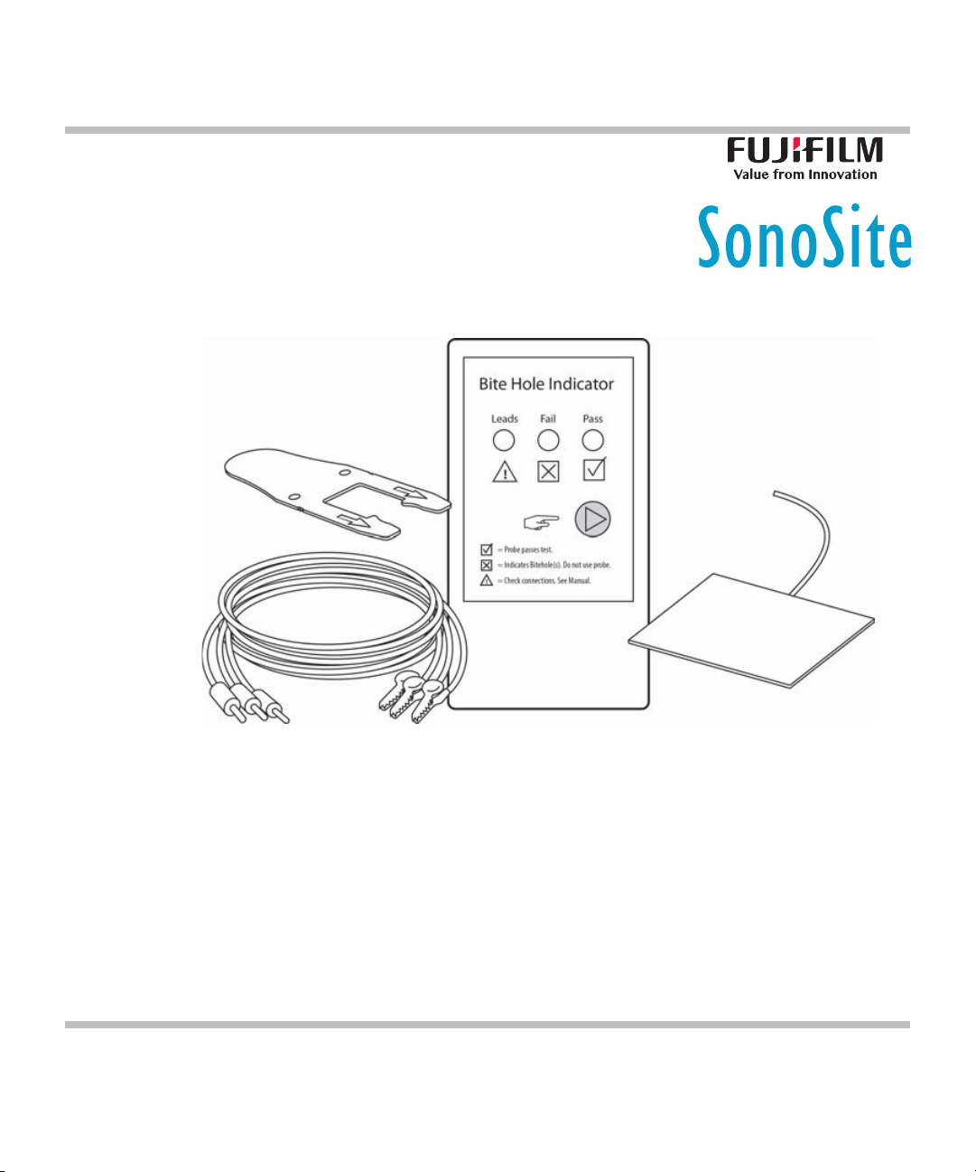
Bite Hole Indicator User Guide
Introduction ..................................................................................................................................................... 1
Document conventions ........................................................................................................................................................................... 1
Getting help ................................................................................................................................................................................................... 1
Overview ......................................................................................................................................................... 2
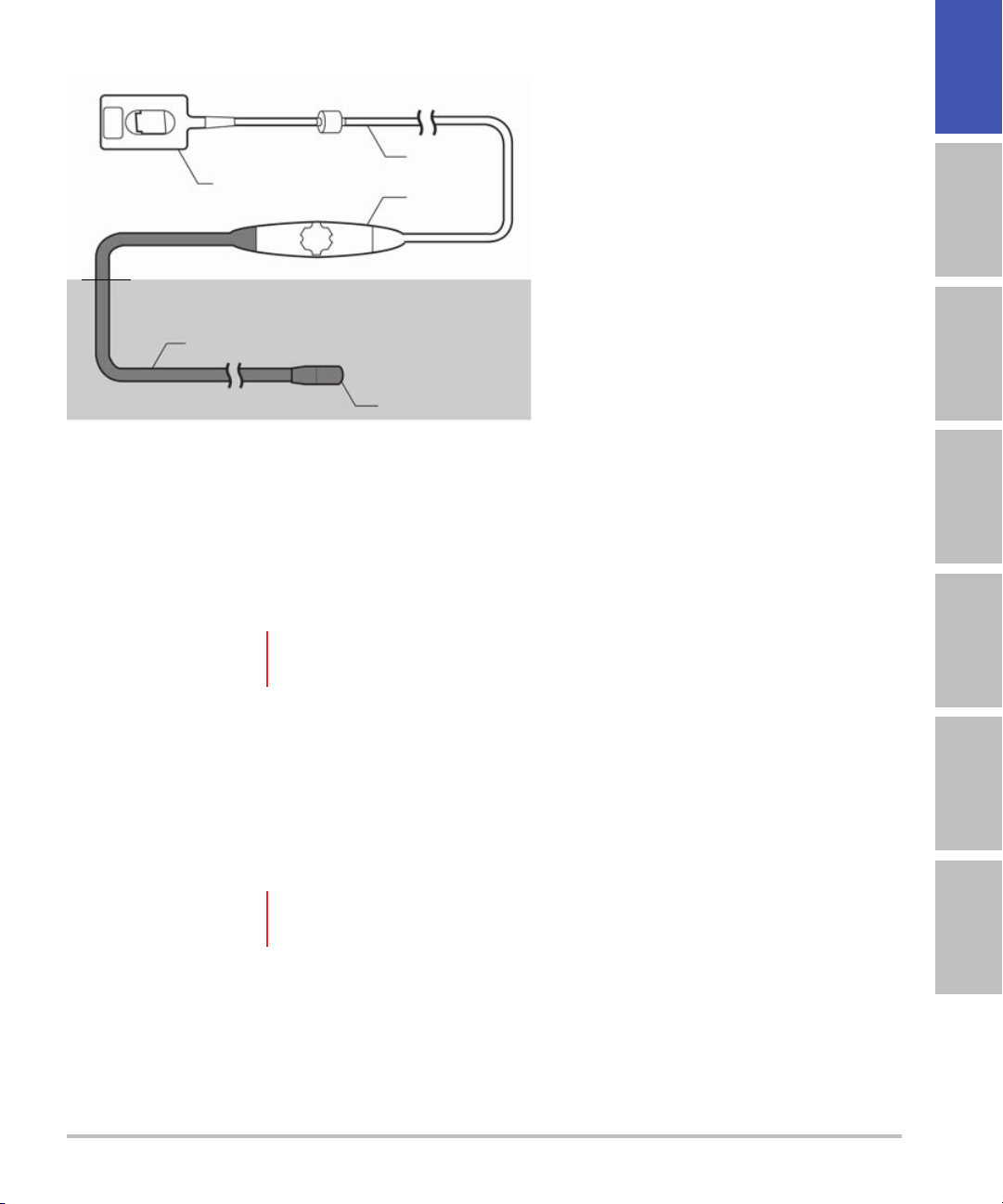
Transducer components ......................................................................................................................................................................... 2
Testing for bite holes ..................................................................................................................................... 3
Preparing for bite-hole testing ............................................................................................................................................................ 3
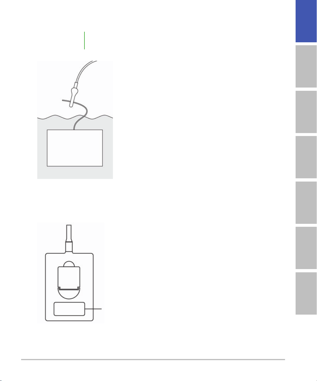
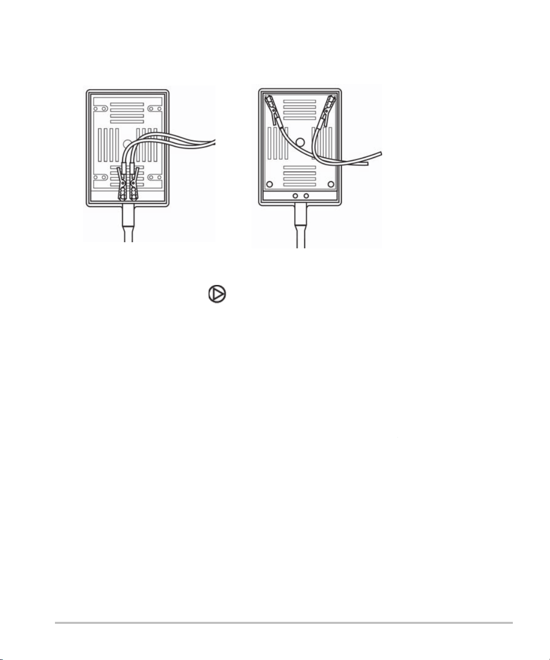
Step 1 — Testing the transducer array (TEEx, TEExi, and TEExp) .................................................................................. 4
Step 2 — Testing the endoscopic shaft (TEExi and TEExp only) ..................................................................................... 7
Step 3 — Cleaning the transducer (TEEx, TEExi, and TEExp) ........................................................................................... 9
If no bite holes are detected ............................................................................................................................................................. 10
If the transducer fails the test ........................................................................................................................................................... 10
Introduction
It is important that you test the TEEx, TEExi,or TEExp transducer for punctures and tears in the waterproof
coating before every procedure. If any damage, irregularity, substandard functioning, or unsafe condition is
observed or suspected, do not use the transducer. Call FUJIFILM SonoSite or your local representative.
Document conventions
The document follows these conventions:
A WARNING describes precautions necessary to prevent injury or loss of life.
A Caution describes precautions necessary to protect the products.
A Note provides supplemental information.
Numbered and lettered steps must be performed in a specific order.
Bulleted lists present information in list format but do not imply a sequence.
Getting help
In addition to this document, you can get help with this product by contacting FUJIFILM SonoSite Technical
Support:
Phone
(U.S. or Canada)
877-657-8118