Fujioh BUF-07W User manual

READ AND SAVE THESE INSTRUCTIONS.
Keep this manual in a convenient place for future reference.
FUJI INDUSTRIAL CO., LTD.
TABLE OF CONTENTS
Safety Instructions................................................................................................ 2, 3
Name of Parts .......................................................................................................... 4
Circuit Diagram ........................................................................................................ 4
Dimensions/Accessories...................................................................................... 5, 6
Range Hood Location .............................................................................................. 7
Installation.......................................................................................................... 8~22
1. Preparation .................................................................................................. 8, 9
2. Range Hood Mounting ............................................................................... 9~17
Mounting Procedure for BUF-07W (Wall Mounting)............................... 9~13
Mounting Procedure for BUF-07P (Ceiling Mounting) ......................... 14~17
3. Connecting Power Supply Wires.............................................................. 18, 19
4. Final Assembly and Check....................................................................... 19~22
5. Explanation to the End User by Installer........................................................ 22
Installation Manual
RANGE HOOD
MODEL: BUF-07W
BUF-07P
BUF-07W/P
1U03 3081
*1U033081*

2
SAFETY INSTRUCTIONS
Before installation and operation, read these instructions carefully and use this product only in the manner described
by the manufacturer in the operation manual.
The instruction shown below are used to alert you to potential personal injury and property damage hazards.
There are three hazard classifications based on potentially dangerous situations.
Obey all safety instructions that show these symbols to avoid possible injury, death and/or property damage.
WARNING:WARNING indicates a potentially hazardous situation which, if not avoided,
could result in death or serious injury.
CAUTION:CAUTION indicates a potentially hazardous situation which, if not avoided,
may result in minor or moderate injury.
CAUTION:CAUTION used without the safety alert symbol indicates a potentially
hazardous situation which, if not avoided, may result in property damage.
WARNING
1. TO REDUCE THE RISK OF FIRE, ELECTRIC SHOCK, OR INJURY TO PERSONS, OBSERVE
THE FOLLOWING:
a) Use this unit only in the manner intended by the manufacturer. If you have questions, contact the
manufacturer.
b) Before servicing or cleaning the unit, switch power off at service panel and lock the service
disconnecting means to prevent power from being switched on accidentally. When the service
disconnecting means cannot be locked, securely fasten a prominent warning device, such as a tag,
to the service panel.
2. To reduce the risk of fire or electric shock, do not use this product with any solid-state speed control
device.
3. TO REDUCE THE RISK OF FIRE, ELECTRIC SHOCK, OR INJURY TO PERSONS, OBSERVE
THE FOLLOWING:
a) Installation work and electrical wiring must be done by a qualified person(s) in accordance with all
applicable codes and standards, including fire-rated construction.
b) Sufficient air is needed for proper combustion and exhausting of gases through the flue (chimney)
of fuel burning equipment to prevent back drafting. Follow the heating equipment manufacturer’s
guidelines and safety standards such as those published by the National Fire Protection Association
(NFPA), and The American Society for Heating, Refrigeration and Air Conditioning Engineers
(ASHRAE), and the local code authorities.
c) When cutting or drilling into wall or ceiling, do not damage electrical wiring and other hidden utilities.
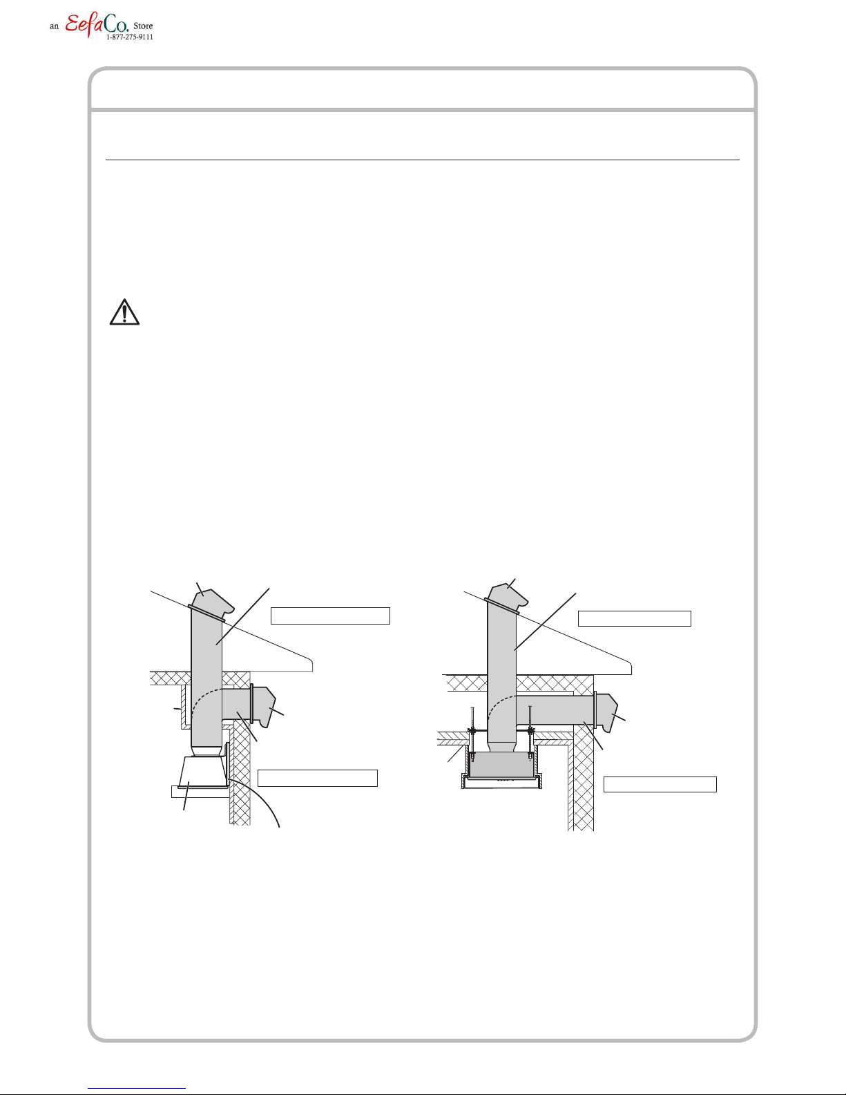
d) Ducted fan must always be vented to outdoors.
e) The end user is responsible to ensure compliance with all Federal, State and Local Environmental
and Fire codes.
4. TO REDUCE THE RISK OF FIRE, USE ONLY METAL DUCTWORK.
5. This unit must be grounded.
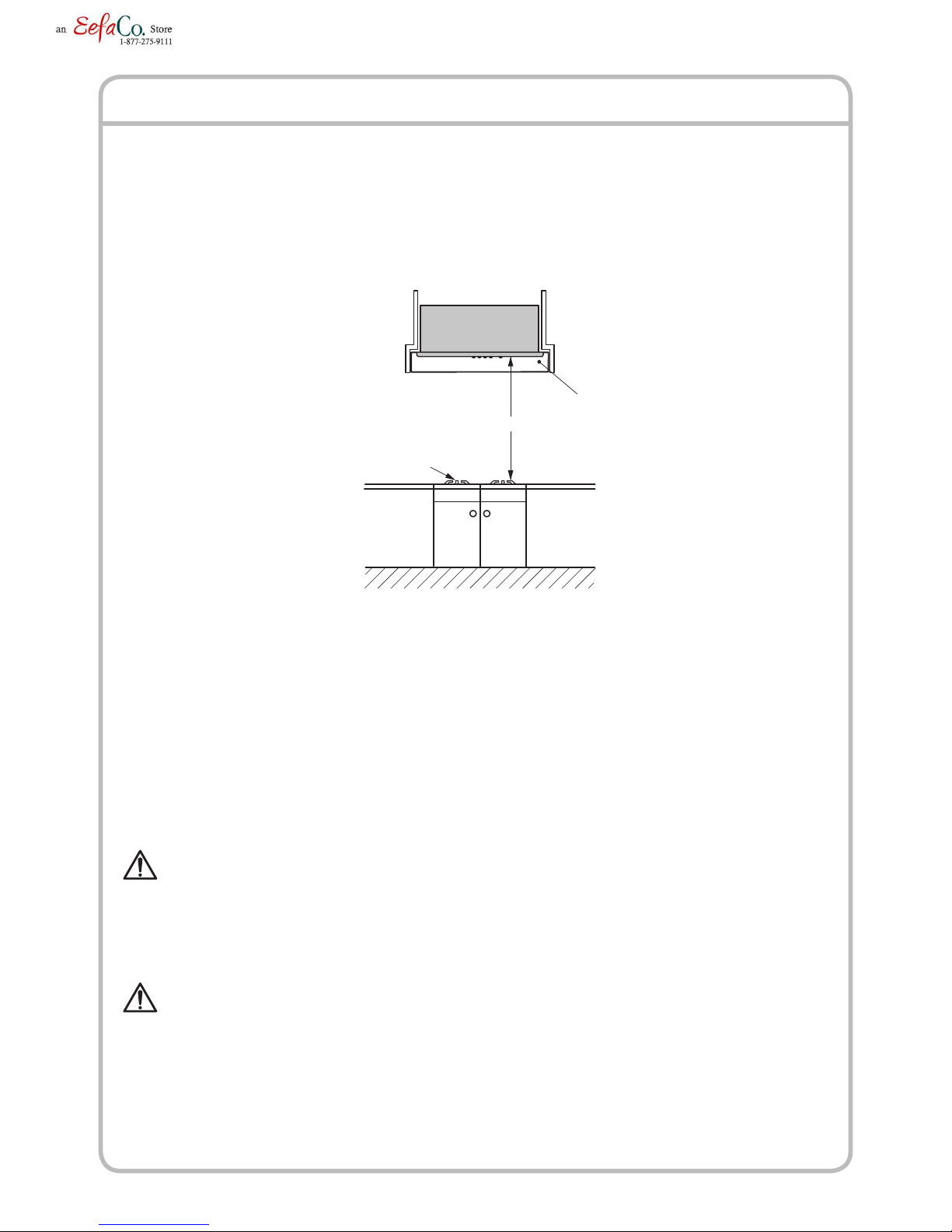
6. Install this range hood to a liner. Check that the hood is correctly installed, since incorrect installation
could result in the range hood becoming detached and falling off.
7. Connect only to an AC120 Volt power source or the range hood could result in fire, electric shock,
and damage.

3
: means prohibition. It indicates actions, if any, that
mustn’t be done.
: means forcible execution. It indicates actions, if any,
that must be done.
NOTE: The safety instructions are explained with the following
pictographic symbols.
CAUTION
1. For general ventilating use only. Do not use to exhaust hazardous or explosive material and vapors.
2. To reduce the risk of fire and to properly exhaust air, be sure to duct air outside. Do not vent exhaust
air into spaces within walls, ceilings or into attics, crawl spaces or garages.
3. Read specification label on this product for further information and requirements.
4. Use only for the purpose of kitchen ventilation.
5. Do not install this range hood in the bathroom or in other wet rooms since electrical shock and
damage may result.
6. Fasten the filter and other parts securely. Incorrect attachment may result in personal injury or
property damage.
7. Keep your hands and other objects away from the fan while it is in motion. The range hood may
injure you or damage itself.

4
NAME OF PARTS
CIRCUIT DIAGRAM
Hanging
Bracket
(only W model)
Fan Switch
Front Cover
Enclosure
Filter
Lamp Switch
Lamp Switch
High Switch
Medium SwitchLow Switch
OFF Switch
Pilot Lamp
Lamp (Not supplied)
(PAR20 bulb, in the base diameter
26mm: medium base)
AC120V
60Hz
Connector
Connector
Connector
Connector
Motor Motor
Yellow
Orange
Black
Blue
Gray
Brown
Orange
Black
BlackBlack
Black
Black
Black
Black
Blue
Gray
Brown
Red
Green
Orange
White
White
White
Black
White
Black
White
White
Black
Blue
Blue
Brown
Red
White
Black
Blue
Yellow
Yellow
Gray
Brown
Brown
Brown
Pilot Lamp
Lamp
50W
Lamp
50W
Fan Switch Lamp Switch
Relay Relay Relay
6:Orange
3:Black
8:Orange
6:Orange
3:Black
8:Orange
6:Orange
3:Black
8:Orange
7:White
7:White
7:White
Connector
High
Switch
Medium
Switch
Low
Switch
Capacitor
BUF-07W/P

5
DIMENSIONS/ACCESSORIES
BUF-07W
17-11/16"
9-15/16"
12-3/8"12-3/8"
16-7/8"
4-13/16"
11-3/4"
7/8"
6-1/16"
27"
25-1/16" ∅7/8"
26"
9-7/8"
6-5/8"
7-7/8"
15-3/4"
10"
9/16"
5/8"
4-3/4"
2-3/8"
19-11/16"
14-5/8"
1" 10-7/8"
2-15/16"
(Unit : inch)
Accessories
Screw M5.1×45
Six (6) pieces
Screw M5×30
Four (4) pieces
Screw M5×10
Four (4) pieces
Screw M4×10
Four (4) pieces
Nut with plate
Four (4) pieces
Hanging bracket
Two (2) pieces
Exhaust pipe unit
One (1) piece

6
DIMENSIONS/ACCESORIES (continued)
(Unit : inch)
BUF-07P
17-11/16"
9-7/8"
12-3/8"12-3/8"
16-7/8"
4-13/16"
11-3/4"
7/8"
6-1/16"
27"
25-1/16" ∅7/8"
26"
16-15/16"
9-8/7"
6-5/8"
7-7/8"
15-11/16"
12"
10"
19/32"
5/8"
4-3/4"
2-15/16"
4-3/8"
2-13/16"
Accessories
Screw M5×30
Four (4) pieces
Screw M4×8
Four (4) pieces
Nut with plate
Four (4) pieces
Mounting bracket
One (1) piece

7
1
The range hood must be installed just above the cooktop.
2
The minimum distance from the cooking surface to the bottom of the range hood must
be 24”.
3
The total weight of the BUF-07W and BUF-07P range hood unit are;
BUF-07W: 50.9 lbs. (23 kg)
BUF-07P: 50.9 lbs. (23 kg)
4
Power requirements are:
AC120 V, 60 Hz, 8.7 Amp
RANGE HOOD LOCATION
CAUTION
• Toprotecthandsfrominjury,wearworkinggloveswheninstallingtherangehood.
WARNING
• Checkthatthehoodiscorrectlyinstalled,sinceincorrectinstallationcouldresultinthe
detachment of the range hood and the unit could fall.
24" (Minimum)
Cook top
Liner

8
INSTALLATION
1. Preparation
WARNING
• Iftherangehoodisnotinstalledproperly,itcouldbecomedetachedandfall.
• Ensurethatthemetalductdoesnottouchothermetal/housingmaterials,
otherwise fire or electric shock could result.
1
This range hood is designed to discharge upward from the unit, but may vent
horizontal above the unit. For vertical discharge, run duct work between the hood
location and roof cap location.
To get the best result, use a minimum number of transitons and elbows.
Be sure to attach a roof/wall cap to avoid rain from entering the exhaust duct.
Roof cap
Soffit
Duct
(For vertical discharge)
Wall cap
Duct
(For holizontal discharge)
Note: 10" round duct
BUF-07P
Range hood
Soffit
Roof cap Duct
(For vertical discharge)
Wall cap
3/4" thickness
wood panel is required
Note: 10" round duct
Duct
(For holizontal discharge)
BUF-07W
The following method is the standard installation.
There may be some different cases depending on the structure where the mounting
bracket is placed or the shape and mounting condition of the wood hood.
In such a case, please arrange best possible way according to the condition of the place
where the range hood is being installed.

9
INSTALLATION (continued)
2. Range Hood Mounting
CAUTION
• Thelinershapeillustratedinthisinstallationmanualisonlyforreference.
• Whenthelinerisinstalledinthewoodenhood,theinsideofthewoodenhoodplaced
above the cooking surface must be fully covered by the metal barrier including bottom
edges. Select a suitable liner and metal barrier according to the size and shape of the
wooden hood and install properly.
• Thelinershouldbeinstalledtightly.Ifthelinerinstallationisnotcorrect,therangehood
unit may become detached and fall.
CAUTION
• Wearworkingglovestoavoidinjury.
2
The range hood unit should be
mounted to a liner which has the
dimensions stated in diagram. Install
the liner securely after checking that
the opening size of the liner is the
same as the figure shown.
Note
During installation, be careful not to touch the fan switches.
If two or more switches are pushed at once, it may cause
failure to the motors.
26"
15-15/16"
25-3/16"
9-13/16"
min. 11/16"
4-∅1/4"
FWD Switches & lamps side
Center line
FrontLiner
Liner cutout
Holes for mounting
range hood
Mounting procedure for BUF-07W (Wall Mounting)
*For the procedure to mount BUF-07P (Ceiling Mounting), see page 14.
1
Before mounting, make sure that a wood panel for
mounting the range hood is fixed on the wall where
the range hood is installed.
Note
If no wood panel is found on the wall, be sure to
prepare one referring to the figure.
Liner
Fan unit
Wall
3/4" thickness
wood panel is required

10
INSTALLATION (continued)
2
Place the range hood as shown and
detach the left and right filters by loosening
2 screws.
Then remove 5 screws fixing the front
cover and detach the front cover.
Front cover
Loosen 2 screws
to remove the filter.
Filter
3
Remove the sound-absorbing boxes.
(1) Remove the two screws holding
each front sound-absorbing boxes
(2 pcs), pull the tab at the top of
the box out of the slit, and remove
the box.
Sound-absorbing box (rear)
Sound-absorbing box
(front)
(2) Remove the two screws holding
the rear sound-absorbing box,
pull the tab at the top of the box
out of the slit, and remove the
box.
(3) Remove the two screws holding
the sound-absorbing boxes on
each side, pull the tab at the top
of the box out of the slit, and
remove the box.
Sound-absorbing box
(left side)
Sound-absorbing box
(right side)

11
INSTALLATION (continued)
4
Remove the fan unit.
(1) Disconnect wiring connector
coming from the fan unit.
(2) Remove 5 screws from the
fan unit.
(3) There are three screws
holding the sliding bracket
(right side); remove the
middle screw, loosen the
other two, and move the
sliding bracket so as to free
the edge of the fan unit.
FWD Screw
2
Connector
Push with a
screwdriver etc,
and pull off.
Fan unit
1
3Slide
Loosen
Loosen
Sliding
Bracke
t
FWD
1
32
Sliding BracketFixed Bracket
(rear)
Fixed Bracket
(side)
(4) Move the fan unit forward to
free it from the fixed bracket
(rear) ( ➀).
(5) Lift the right side of the fan unit
(sliding bracket side) ( ➁).
(6) Move the fan unit to the right to
release it from the fixed bracket
(left side) ( ➂).
(7) Remove the screw securing the wire
cover for the power supply box and
remove the wire cover by sliding it in
the direction of the arrow to release
the hook.
(8) Need to connect the wires.
Wire coverHook
Note
Make sure not to misplace the screws
removed as they will be used later.
Note
Make sure not to lose the screw
removed from wire cover. It needs to
be used again later, after connecting
the power supply wires.

12
INSTALLATION (continued)
5
Place the range hood in an upright
position and attach the exhaust
pipe unit using the 4 (M4×8)
attachment screws provided. Once
the exhaust pipe unit is securely
attached, remove the tape.
Exhaust pipe unit
Tape
6
Align 4 screw holes
of the liner and
range hood, then
fix securely using
the supplied screws
(M5×30) and nuts.
Note
Fasten all the screws
and nuts evenly.
Liner
Nut with plate
Liner
[Securing plate
turns while
passing through
the opening
of Liner]
Securing plate
Nut with plate
[Right & left, each two (2) places]
Four screws
(M5×30)
7
Fix the supplied hanging bracket
on the body firmly using 4 supplied
screws (M5×10).
8
Referring to "Dimensions" on page 5, insert the
washer-head wood screws (M5.1×45) into the
mounting wall to align with bracket keyhole (left and
right). Allow about 5mm between the screwheads and
wall for mounting the range hood.
2"(5)
Wood
p
anel
Wall

13
INSTALLATION (continued)
9
Hook the temporary fixing holes of the hanging
bracket on the washer-head wood screws
prepared in step 8, and tighten the screws.
10
Add 2 screws (M5.1×45) to the holes
under the temporary fixing holes and
tighten them securely.
11
Fix the range hood securely using 2 supplied
wood screws (M5.1×45) to the holes on the
back of the range hood.
12
Make the duct joint secure and air-
tight using non-flammable tape such as
aluminum tape, etc. (not supplied)
Note
Insert tight the exhaust pipe unit into
the duct.
Duct
Non-flammable
tape

14
INSTALLATION (continued)
Mounting procedure for BUF-07P (Ceiling Mounting)
1
Put 4 all thread rods (∅1/2'' anchor
bolt, not supplied) into the corner holes
of the mounting bracket, and secure
them using washers, spring washers,
and nuts. Place the mounting bracket
on the beam of the ceiling as shown.
2
Place the range hood as shown and
detach the left and right filters by loosening
2 screws. Then remove 5 screws fixing the
front cover and detach the front cover.
Note
The mounting bracket should
be securely fastened at this
point to simplify installing the
range hood later.
Beam
Mounting bracket
Washer*
Mounting Bracket
*Not supplied
Spring-washer*
Nut*
Front cover
Loosen 2 screws
to remove the filter.
Filter
3
Remove the sound-absorbing boxes.
(1) Remove the two screws holding
each front sound-absorbing boxes
(2 pcs), pull the tab at the top of
the box out of the slit, and remove
the box.
Sound-absorbing box
(front)

15
INSTALLATION (continued)
4
Remove the fan unit.
(1) Disconnect wiring connector
coming from the fan unit.
(2) Remove 5 screws from the
fan unit.
(3) There are three screws
holding the sliding bracket
(right side); remove the
middle screw, loosen the
other two, and move the
sliding bracket so as to free
the edge of the fan unit.
FWD Screw
2
Connector
Push with a
screwdriver etc,
and pull off.
Fan unit
1
3Slide
Loosen
Loosen
Sliding
Bracke
t
Sound-absorbing box (rear)
(2) Remove the two screws holding
the rear sound-absorbing box,
pull the tab at the top of the box
out of the slit, and remove the
box.
(3) Remove the two screws holding
the sound-absorbing box on
each side, pull the tab at the top
of the box out of the slit, and
remove the box.
Sound-absorbing box
(left side)
Sound-absorbing box
(right side)
Note
Make sure not to misplace the screws
removed as they will be used later.

16
INSTALLATION (continued)
(4) Move the fan unit forward to
free it from the fixed bracket
(rear) ( ➀).
(5) Lift the right side of the fan unit
(sliding bracket side) ( ➁).
(6) Move the fan unit to the right to
release it from the fixed bracket
(left side) ( ➂).
(7) Remove the screw securing the
wire cover for the power supply
box and remove the wire cover
by sliding it in the direction of
the arrow to release the hook.
(8) Need to connect the wires.
4
Place the range hood in an
upright position and attach the
exhaust pipe unit using the
4 (M4×8) attachment screws
provided. Once the exhaust pipe
unit is securely attached, remove
the tape.
Note
Make sure not to lose the screw
removed from wire cover. It needs to
be used again later, after connecting
the power supply wires.
Wire coverHook
Exhaust pipe unit
Tape
FWD
1
32
Sliding BracketFixed Bracket
(rear)
Fixed Bracket
(side)

17
5
Align 4 screw holes
of the liner and
range hood, then
fix securely using
the supplied screws
(M5×30) and nuts.
Note
Fasten all the screws
and nuts evenly.
Liner
Nut with plate
Liner
[Securing plate
turns while
passing through
the opening
of Liner]
Securing plate
Nut with plate
[Right & left, each two (2) places]
Four screws
(M5×30)
INSTALLATION (continued)
6
Hold up the range hood, while
inserting the exhaust pipe unit into the
duct, pass all 4 threaded rods through
the holes of the mounting bracket.
7
Using washers, spring
washers, and double nuts,
attach the range hood
to all 4 threaded rods
securely.
Washer*
Washer*
Spring-
washer*
Spring-
washer*
Nut*
Attachment
*Not supplied
11/16"
or less
Attachment
Note
If taping from the outside is impossible, remove the exhaust pipe unit and insert the
duct end to the range hood directly, then make inside taping on the duct end. Be sure
to attach a roof/wall cap with damper in this case.

18
INSTALLATION (continued)
3. Connecting Power Supply Wires
WARNING
• Electricalwiringshouldbedonebyaqualiedperson(s)inaccordancewithallapplicable
codes and standards, including fire-rated construction. An unqualified person doing the
work could result in fire, electric shock or injury.
• Thisrangehooduses120VAC.Donotconnecttoothervoltagesincere,electricshock
or damage could result.
WARNING
• BesuretoswitchpowerOFFatservicepanelbeforewiring.
1
Remove the nut from the conduit connector at the end of
power wiring.
3
Connect wires tightly and securely using
wire connectors (not supplied).
Connect the electrical wires as follows:
•BlacktoBlack
•WhitetoWhite
•GreentoGreen
2
Connect the
conduit through the
connecting hole of
the enclosure using
the nut previously
removed.
Conduit
(Not supplied)
Nut
(Not supplied)
Conduit
Nut

19
INSTALLATION (continued)
4
Slide the wire cover on and insert the hook. Secure
the wire cover with the screw removed previously.
Make sure that all wires are connected properly
and enclosed inside the wiring compartment.
Wire cover
Hook
Screw
4. Final Assembly and Check
1
Attach the fan unit.
(1) Insert the left side edge of
the fan unit under the fixed
bracket (left side, ➀), let
the right side of the fan unit
drop into place and move
the sliding bracket ( ➁)
back to where it covers the
right edge of the fan unit.
(2) Slide the fan unit to the rear
and into the fixed bracket
(rear, ➂).
(3) Tighten the two screws
of the sliding bracket and
secure the bracket by
inserting and tightening
the middle screw removed
previously ( ➃).
1
3
FWD
Slide
2
4
Sliding Bracket
Fixed Bracket
(rear)
Fixed Bracket
(side)

20
INSTALLATION (continued)
3
Connect the fan unit’s wiring connector.
Note
Be sure to connect firmly as illustrated.
4
Reinstall the sound-absorbing boxes in
the following order: side, rear, front.
Connector
FWD
Sound-absorbing box (left)
Sound-absorbing box (right)
(1) For the sound-absorbing boxes
on each side, insert the tab at the
top part of the box into the slit and
secure in place by affixing the two
screws at the bottom of the box.
CAUTION
• Checkthatthefanunitishanged
securely when attaching. It may
cause injury if dropped.
2
While holding the fan unit,
firmly attach it to the main
unit using 5 screws.
Fan unit
Scre
w
This manual suits for next models
1
Table of contents
Other Fujioh Ventilation Hood manuals

Fujioh
Fujioh BUF-06W User manual

Fujioh
Fujioh BUF-03A User manual

Fujioh
Fujioh ECP-360 User manual

Fujioh
Fujioh BUF-03R User manual

Fujioh
Fujioh ECP-360 User manual

Fujioh
Fujioh ECW-360 User manual

Fujioh
Fujioh BUF-08P User manual

Fujioh
Fujioh BUF-0 User manual

Fujioh
Fujioh FSR-3600S User manual

Fujioh
Fujioh BUF-06W User manual

Fujioh
Fujioh EBW-600 User manual

Fujioh
Fujioh NL-900R User manual

Fujioh
Fujioh FR-MS1970V User manual

Fujioh
Fujioh MF-1100V User manual

Fujioh
Fujioh BUF-01M User manual

Fujioh
Fujioh GFP-600 User manual

Fujioh
Fujioh FJS-900V User manual

Fujioh
Fujioh BUF-06E User manual

Fujioh
Fujioh BUF-01 User manual

Fujioh
Fujioh BUF-01A User manual