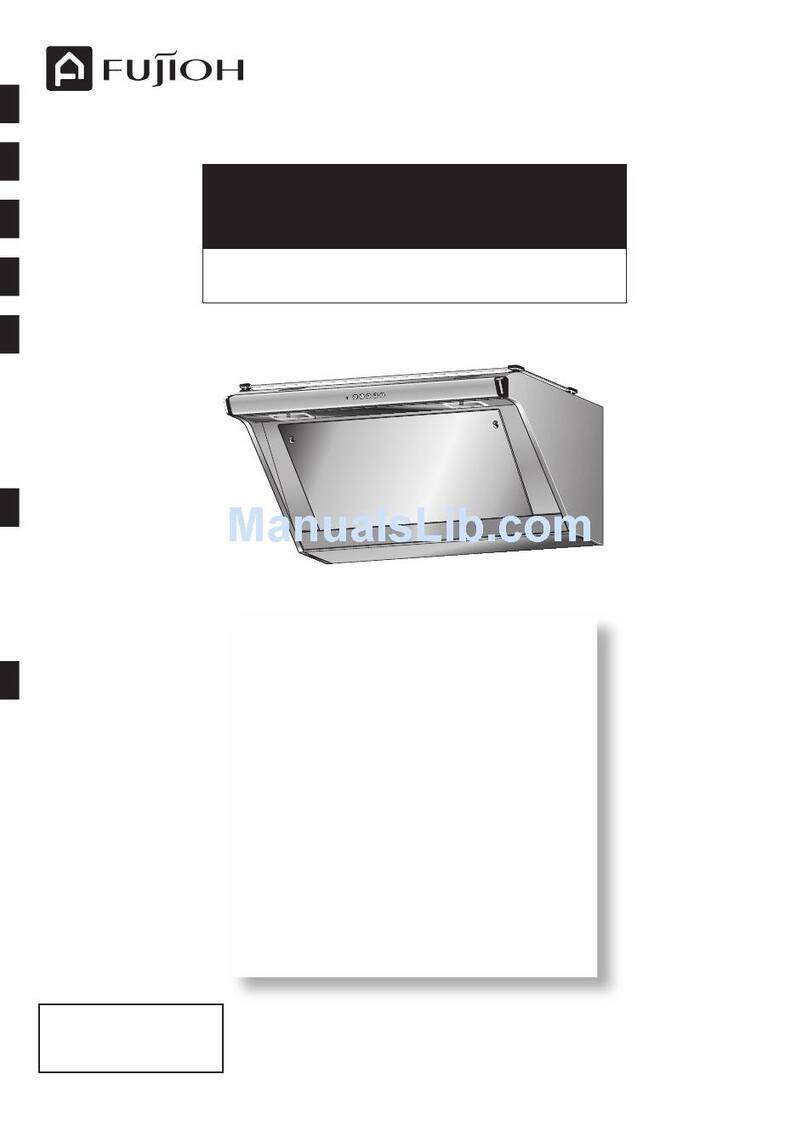
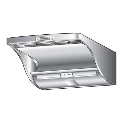
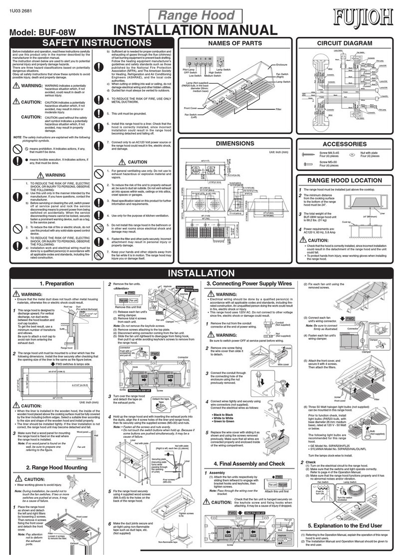
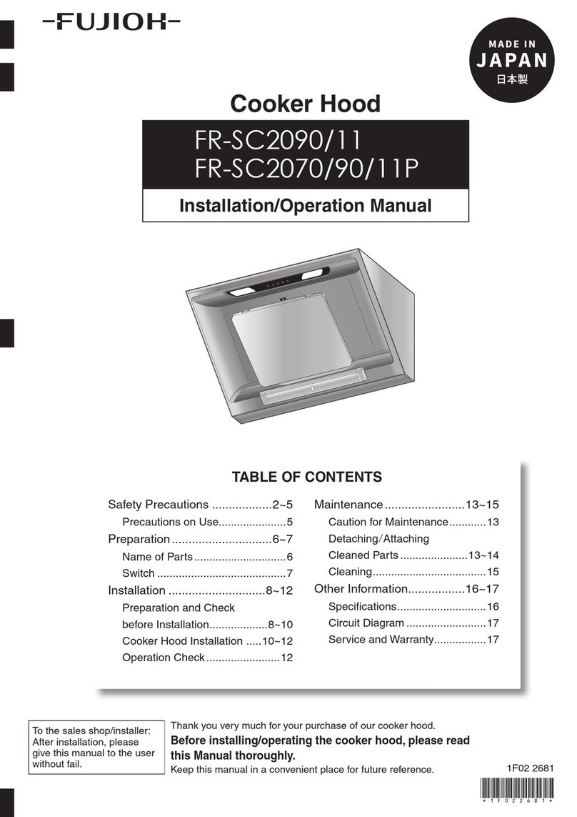
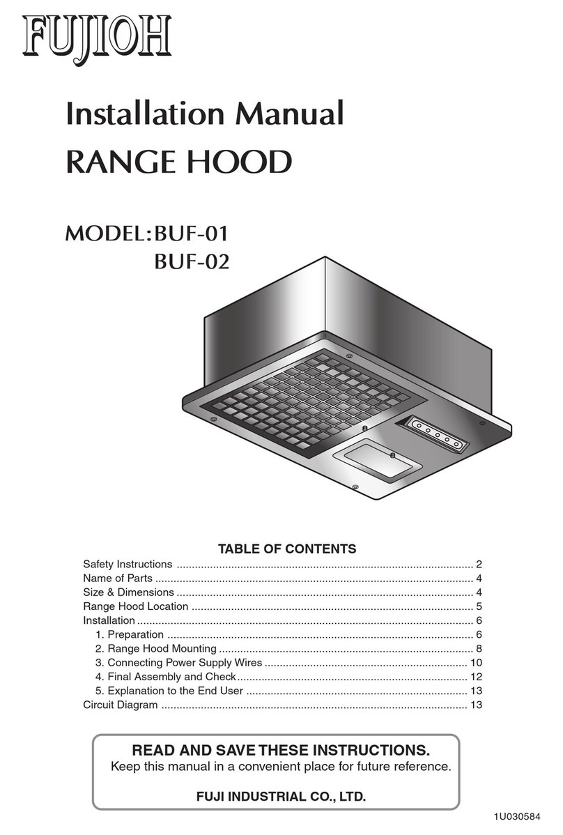
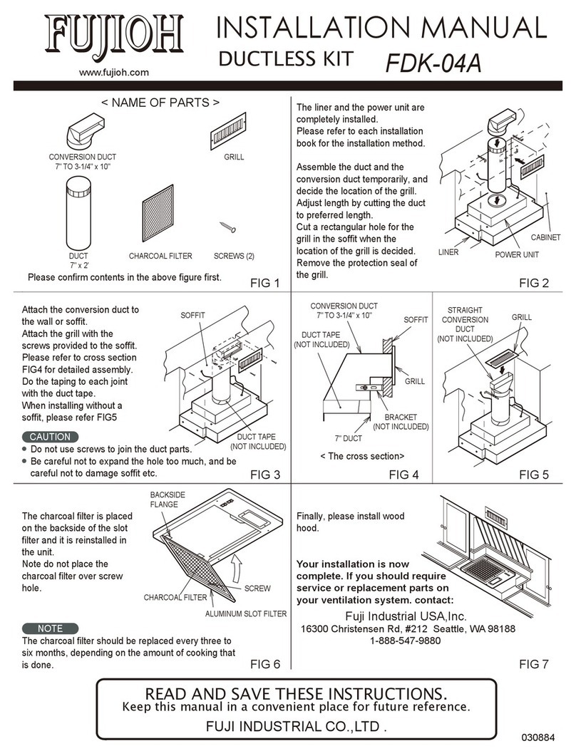
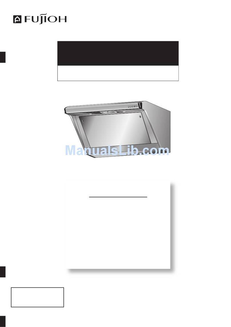
Fujioh FR-SD2290V User manual

FR-SD2290V
Instruction Manual
Cooker Hood

2
2
2
3
4
5
5
6
11
12
13
15
Warning
Caution
Safety warning
Packing list
Product structure schematic
Outline dimension
Installation guide
Control panel operation
Troubleshooting
Maintenance
Electrical schematic diagram
Specifications
1
Warning
Caution
This appliance is not intended for use by persons (including children) with reduced physical,
sensory or mental capabilities, or lack of experience and knowledge, unless they have been
given supervision or instruction concerning use of the appliance by a person responsible for
their safety. Children shall not play with the appliance. Cleaning and user maintenance shall
not be made by children without supervision. If the supply cord is damaged, it must be
replaced by the manufacturer, its service agent or similarly qualified persons in order to
avoid a hazard.
There shall be adequate ventilation of the room when the cooker hood is used at the same
time as appliances such as burning gas or other fuels.
Please do not use corrosive detergent for cleaning. The proper function of the unit is
conditioned by the regularity of the maintenance.
To protect the main body from corrosive formed by the long time accumulation of dirt, the cooker
hood should be cleaned with hot water with non-corrosive detergent in every two months.
There is a fire risk if cleaning is not carried out in accordance with the instructions.
Do not flame under the cooker hood.
The air must not be discharged into a flue that is used for exhausting fumes from
appliances such as burning gas or other fuels.
The minimum distance between the top most part of the cooking appliance such as gas hob
and the lowest part of the cooker hood, when it is located exactly over the cooking appliance,
shall be at least 300mm. If greater distance is specified in the manual of the cooking appliance,
it must be taken into account.
Regulations concerning the discharge of air must be fulfilled.
●
●
●
●
●
●
●
●
●
Accessible parts may become hot when used with cooking appliances.
This hood is an external exhaust type cooker hood, and the gas the cooker hood machine
should not be discharged into the hot flue gas used for the discharge of smoke produced
through burning gas or other fuel.
If the cooker hood is installed above the gas stove, the distance from the bottom of the body
to the focal plane is at least 300mm, which should be considered if the installation instruc-
tions of gas-fired stoves provide a larger installation distance.
It is strictly forbidden to modify the product without authorization, and the power cord shall
not be replaced or modified by itself.
Please do not install the cooker hood machine on the wall of flammable material.
Do not install the cooker hood machine on the top of the stove with solid fuel.
When drilling holes in the wall, avoid electrical wires embedded in the wall to avoid electric
shock hazard.
A special power supply socket shall be used for the cooker hood machine, and the special
power outlet should be reliably grounded (the product must use 10A, 220~V or above).
The wall shall have sufficient supporting strength for the installation of the cooker hood
machine. The hollow core of the wall shall be greater than 30mm, and the concrete
wall can be directly punched and installed. The product must be securely mounted on the
wall.
The cooker hood may have very sharp edges. Please wear protective gloves when
you install or clean the cooker hood.
If your kitchen is under a state of decoration, do not use cooker hood exposed, for building
materials, dust, paint, coatings and their volatile gas cooker hood surface causes corrosion
and lose luster, please install cooker hood in after the decoration.
●
●
●
●
●
●
●
●
●
●
●
15
Contents

34
Packing list
The following product components are attached to the product
package.Please check them after opening. If they are not
complete,please contact the service center or dealers.
Name
2pcs
2pcs
No .
1
2
3
4
5
6
7
8
9
10
11
12
13
Quantity
1pcs
1pcs
1pcs
1pcs
7
7
2
1
1
1
1
pcs
pcs
pcs
pcs
pcs
pcs
pcs
The appliance is not intended for use by young children or infirm
persons without supervisions.
Young children should be supervised to ensure they do not play with
the appliance.
Plug the power cord to socket outlet with earthing continuity terminal.
The cooker hood is for home use only, not suitable for barbecue, roast
shop and other commercial purposes.
The cooker hood and its filter should be cleaned regularly according to
the instruction.
Do not use open flame, or allow the appliance.
If the supply cord is damaged, it must be replaced by the manufacturer,
service agent or similarly qualified person in order to avoid a hazard.
The replaced power cord should be provided by manufacturer or seller.
There is a fire risk if cleaning is not carried out in accordance to the
instruction.
In case of damaged connecting wire, please refer to the manufacturer,
after-sale service personnel or other qualified technicians.
Use the product according to the instructions to avoid any fire hazard.
The exhaust air must not be introduced into a smoke flue or chimney
that is used for exhausting fumes from appliances such as burning gas.
Follow the local laws applicable for external air evacuation.
Safety warning
Please ensure that there is an adequate ventilation in the room while
the cooker hood is in operation.
Please ensure that the power plug is disconnected from the socket or
turn off the breaker before cleaning or maintaining the hood.
flame to go beneath
141pcs
Main unit
Hanging bracket
Exhaust outlet
Flexible Tube Duct
Plastic expansion pipe(Φ10)
Wood screw(ST5x50)
Screw(ST4x10)
Screw(M4x10)
Slide duct cover fixing sheet
Instruction Manual
Pressing plate
Oil tray
Slide duct cover fixing bracket
Slide duct cover

6
Installation guide
5
Mark the mounting position of the hanging bracket
according to the instructions below.
Make sure that the screws are symmetrical on both sides of
the center line with a horizontal distance of 180mm and a
vertical distance of 48mm.
Product structure schematic
Unit:mm
Main unit Control switch
Oil tray
LED light
425±5
362±5
895
473
985-1185
367 268
150-350 with slide duct cover
268
43°
±5°
362
Duct cover
Slide duct cover
910
Ø170
300-550
367
362
268
Outline dimension
To determine the location (unit: mm)
The range hood machine should be installed horizontally and
above the cooker. The installation diagram is as follows.
Installation precautions
After installation of the cooker hood, the left and right level
should be maintained.
Should avoid excessive windows and air convection in the
vicinity of the cooker hood, otherwise it will affect the
efficiency of the cooker hood.
Exhaust pipe requirements.
The exit of the exhaust pipe should not be too long.
●
●
●
●
1.
Cooker hood installation(unit: mm)

8
7
Drill holes with 10mm diameter and 55mm depth on the 4
screw positions marked, insert the plastic expansion pipe
into the hole.
Plastic
expansion
pipe
First fix the hanging bracket with 4 pcs ST5x50 screws.
ST5x50 screws
Adjust slide duct cover (if necessary) to a suitable
height(the screw hole for the slide duct cover fixing bracket
is 20mm from the top of the cabinet), mark the position of 2
screws on the wall, then drill 2 holes with 10mm
diameter and 55mm depth, insert the plastic expansion
pipes into the hole.
260
Slide duct cover fixing bracket
Cooker hood buttom
Hob
Center line
Screws
Plastic expansion pipe
Use 2 ST5x50 screws to attach the slide duct cover
fixing bracket to the wall.
Wall
Slide duct cover
fixing bracket
Install the main unit on the wall. The main unit and the
wall should be tilted 1°to 2°, so that the hook of the main
unit hanging bracket can be fully inserted and hung into
the main unit slot. After hanging the cooker hood, please
check the horizontal and ensure that the main unit is
completely flat with the wall.
Use another ST5x50 screw to fix the pressure plate on
the upper part of the cooker hood (drill a same hole and
insert the expansion pipe as shown in step No.2). Avoid
moving or dropping at running time.
50
ST5x50 screws
Plastic
expansion
pipe
Trough of cooker hood
Hanging Hook
Pressure plate
Cooker
hood
Pressure
plate
ST5x50 screws
300~550
1069~1319
985~1185
Center line
Plastic expansion pipe
Screws
Hanging bracket
Cooker hood buttom
Hob
27.5
20
2.
3.
4.
5.
6.

(inside)
Slide duct cover
Slide duct cover bracket
Slide duct cover
tape
Flexible tube
duct
power cable
Place the exhaust outlet assembly on the gasket. Make
sure the assembly does not interfere with
the circuit board. Secure check assembly to main unit
using set screws to ensure seal.
exhaust outlet
Insert flexible tube duct into exhaust outlet assembly.
Tighten the screws to fix the flexible tube duct to avoid
loosening during operation of the cooker hood, and then wrap
it tightly with tin alminum tape to prevent the leakage of the
smoke and greasy dirt. Use tape to fix the power cord as shown.
Warning
Do not connect the power cable to the surface of the flexible tube duct.
Otherwise, fire or electric shock may occur.
To install the slide duct cover, please pull up the slide duct
cover from the main unit of the cooker hood, and fix the
slide duct cover and the bracket with the fixing screw set.
Please do not let the screw touch the power cord when
fixing.
Oil tray
910
Flexible
tube duct
Cover of circuit board box
Screw(M4x10)
Hold the bottom end of the oil tray with both hands and
place the oil tray horizontally. Insert the oil tray into the
holder and push the oil tray back to the oil tray stents.
Place gasket at exhaust outlet (may need to remove
screws in advance) as shown below. Make sure the
gaskets are aligned correctly. This step can be prepared
in advance depending on the installation space.
Hole position
Hole position
7.
8.
9.
10.
11.
12.
Note
Ensure that the installation screws are tightened, otherwise, the fume
may leak. The flexible tube duct is peoperly stretched and led to
outdoor with bending as little as possbile(generally one bending).The
bending angle must be bigger than 120°,to avoid right -angle.The
end of flexible tube duct should be a little lower to prevent greasy dirt
reflux.

12
11
Control panel operation
Power Low High Heat Clean Light
Press "Power" button will start operation at F02 and open
the glass panel. The screen displays time when first power
on. It will turn to standby if there is no operation within
3mins.
Press"Low" button to lower speed. Speed can be changed
among F01、F02、F03、F04(boost). Press "Low" at F04 will
return to F03.
Light is not under control of "Power" button. Press "Light"
button in stanby state will turn on light and open the glass
panel. Turn off "Light" button will turn off light and the
glass panel. When “Light” and "Power" are both on, press
"Power" will not turn off light and the glass panel.
Press"High" button to raise speed. Long press "High" at F03
to change to F04(boost). It will return to F03 after 1 minute.
Long press "Heat clean" button for 3s in standby state to
start heat clean. The button will flash and screen will
display 30 minutes count down. The process is 10mins
heating→5mins F01 running→10mins heating→5mins
F01 running. When finished, the cooker hood will turn off.
Press "Timer" button at any speed will start 3mins delay.
Then press "High"/"Low" button will cancel timer and change
the speed. Long press "Timer" in standby state to set time.
When the hour area flashes, press "High"/"Low" to change
the number. Press "Timer" again to change the minute area.
Press "Timer" again will finish setting and return to standby.
Fault Possible Cause Solution
Light on, but motor
does not work.
Fan switch turned off. Select a fan switch position.
Fan switch failed. Contact service center.
Motor failed. Contact service center.
Light does not work,
motor does not work.
House fuses blown. Contact service center.
Mains power cable is
loose or disconnected.
Contact service center.
Oil leakage.
One way valve and
the outlet are not
tightly sealed.
Contact service center.
Leakage from the
connection of chimney
and cover.
Contact service center.
Lights does not work. Broken or faulty bulbs. Contact service center.
Insufficient suction.
The distance between
the cooker hood and
the gas top is too far.
Contact service center.
The Cooker hood
inclines.
The fixing screw is not
tight enough. Contact service center.
Timer
Power
Low
High
Timer
Heat Clean
Light
TROUBLESHOOTING

14
13
Maintenance
This product must be cleaned and
maintained frequently for optimal
operating performance and longer
service life. gloves
It is recommended to clean all surfaces
with a wet cloth (neutral detergent may
be used) to maintain the appearance
and hygiene of the product.
Daily cleaning
Point
1. The automatic clean function only cleans the oil of the
casing inside the cooker hood, and does not directly
clean the grease filter.
NOTE:
Any electrical repairs to this appliance must conform to your
local, state and federal laws. Please contact the service centre
if in any doubt before undertaking any of the above actions.
Always disconnect the unit from the power source when
opening the unit.
2. When cleaning the grease filter, do not use strong
alkaline detergent. It is recommended to clean the
grease filter at least once a month.
Oil tray cleaning
Monthly cleaning
Regularly clean the cooker
hood surface with a neutral
detergent and soft cloth.
First turn on the fan to open the
flap, then unplug the power
cord. Clean the filter and
internal surface with a wet cloth
soaked in diluted neutral
detergent. Wipe with dry clean
cloth to dry the cleaned area.
When the oil tray window in the oil tray is filled
with oil, please clean it in time. The oil tray
disassembly procedure is as follows: hold the
lower part of the oil tray with both hands, and
remove the oil tray horizontally;
After cleaning, install the oil
tray in reverse order. (Because
the oil tray is long, please hold
it firmly when the oil tray is
removed so as not to spill the
oil.)
Oil tray

15
Electrical schematic diagram
Control switch
Switching circuit
L Brown
N Blue
E Yellow and green
The
motor
Specifications
LED light information
Max Power Voltage Picture Lamp Cap
Square / Dimension:
170mm x 23mm 2W 12 V ——
Rated voltage
(v) Speed Power consumption
(w)
Air flow
(m³/h)
Sound
(dB)
Boost 134 1020 54
F3 108 955 52
F2 54 750 46
F1 30 605 41
Boost 134 1025 54
F3 109 955 52
F2 54 750 46
F1 30 605 41
Boost 134 1025 54
F3 109 955 52
F2 54 750 46
F1 30 605 41
220
230
240
吸油烟机
使用说明书
使用本电器前,请仔细阅读本说明书。
FR-SD2290V

网站
www.fujioh.com/my
FUJIOH MARKETING MALAYSIA SDN. BHD.
23, Jalan Serendah 26/39, Section 26, 40400
Shah Alam, Selangor, Malaysia
电话:+603- 5103-6826
电子邮箱:[email protected]
2022 年第1 版
目 录
。。。。。。。。。。。。。。。。。。。。。。。。。。。。。。。。。。。。。。。。。。。。。。。。。。。。。。。。。。。。。。。。。。。。。。。。。。。。。。。。。。。。。。。。。。。。。。。。。。。。。。。。。。。。。。。。。。。。。。。。。。。。。。。。。。。。。。。。。。。。。。。。。。。。。。。。。。。。。。。。。。。。。。。。。。。。。。。。。。。。。。。。。。。。。。。。。。。。。。。。。。。。。。。。。。。。。。。。。。。。。。。。。。。。。。。。。。。。。。。。。。。。。。。。。。。。。。。。。。。。。。。。。。。。。。。。。。。。。。。。。。。。。。。。。。。。。。。。。。。。。。。。。。。。。。。。。。。。。。。。。。。。。。。。。。。。。。。。。。。。。。。。。。。。。。。。。。。。。。。。。。。。。。。。。。。。。。。。。。。。。。。。。。。。。。。。。。。。。。。。。。。。。。。。。
2
2
3
4
4
5
5
10
11
11
12
警告
注意
安全警告
包装清单
产品结构示意图
外形尺寸
安装指南
控制面板操作
故障排除
维护
电气原理图
规格 13

规格
LED 灯信息
最大功率 电压 图片 灯头
面积/尺寸
170 毫米 x 23 毫米 2W 12 V --
13
额定电压 (v) 风速 功率 (w) 风量
(m³/h)
噪声
(dB)
爆炒 134 1020 54
F3 108 955 52
F2 54 750 46
F1 30 605 41
爆炒 134 1025 54
F3 109 955 52
F2 54 750 46
F1 30 605 41
爆炒 134 1025 54
F3 109 955 52
F2 54 750 46
F1 30 605 41
220
230
240
警告
。。。。。。。。。。。。。。。。。。。。。。。。。。。。。。。。。。。。。。。。。。。。。。。。。。。。。。。。。。。。。。。。。。。。。。。。。。。。。。。。。。。。。。。。。。。。。。。。。。。。。。。。。。。。。。。。。。。。。。。。。。。。。。。。。。。。。。。。。。。。。。。。。。。。。。。。。。。。。。。。。。。。。。。。。。。。。。。。。。。。。。。。。。。。。。。。。。。。。。。。。。。。。。
本电器不适用于体力、感官或心智能力欠缺或缺乏经验和知识的人(包括儿
童)使用,除非他们得到对其安全负责的人员的监督或指导,可确保安全使
用此电器。儿童不得玩耍本电器。清洁和维护不得由儿童在缺少监督的情况
下进行。如果电源线损坏,必须由制造商、其服务代理或类似的合格专业人
士进行更换,以避免危险。
当油烟机与燃烧气体或其他燃料的设备同时使用时,室内应足够通风。
请勿使用腐蚀性清洁剂进行清洗。设备的正常运行取决于定期维护。
为保护主体不受长时间积累的污垢腐蚀,油烟机应每两个月用热水加无腐
蚀性的清洁剂进行清洗。
如果不按照说明实施清洁,将产生火灾风险。
切勿在油烟机下方点火。
烟气不得排放至用于排放其他废气的烟道,例如烧气或其他燃料的设备所
产生的废气。
当吸油烟机位于灶具正上方时,灶具最顶部(如煤气灶)和吸油烟机最低部
分之间的最小距离至少应为300毫米。如果灶具说明书中规定了更大的距
离,则必须予以考虑。
必须遵守排气相关的规定。
注意
。。。。。。。。。。。。。。。。。。。。。。。。。。。。。。。。。。。。。。。。。。。。。。。。。。。。。。。。。。。。。。。。。。。。。。。。。。。。。。。。。。。。。。。。。。。。。。。。。。。。。。。。。。。。。。。。。。。。。。。。。。。。。。。。。。。。。。。。。。。。。。。。。。。。。。。。。。。。。。。。。。。。。。。。。。。。。。。。。。。。。。。。。。。。。。。。。。。。。。。。。。。。。。
使用灶具时可接触部件温度将升高。
本油烟机为外排式油烟机,油烟机抽出的气体不应排放到热烟气中,
用于排放燃烧燃气或其他燃料产生的烟气。
如果吸油烟机安装在燃气灶上方,则从机身底部到焦平面的距离至少为
300毫米,如果燃气灶的安装说明提供了更大的安装距离,则必须予以考
虑。 严禁未经授权改装产品,不得自行更换或改装电源线。
请勿将油烟机安装在易燃材料的墙壁上。
请勿将油烟机安装在固体燃料灶的顶部。
在墙上钻孔时,应避免将电线嵌入墙内,以免触电危险。
油烟机应使用专用电源插座,专用电源插座应可靠接地(产品必须使用
2

10A、220~V 或以上的插座)。
墙壁应具有足够支撑强度,以便安装吸油烟机。墙体空心应大于 30 毫
米,可以直接在混凝土墙上打孔安装。产品必须牢固地安装在墙上。
吸油烟机可能有锐边。在安装或清洁吸油烟机时,请戴上防护手套。
如果您的厨房正在装修,请勿使用暴露在外的吸油烟机,因为建材、灰
尘、油漆、涂料及其挥发性气体会对吸油烟机表面造成腐蚀并使其失去光
泽,请在装修完后安装吸油烟机。
安全警告
。。。。。。。。。。。。。。。。。。。。。。。。。。。。。。。。。。。。。。。。。。。。。。。。。。。。。。。。。。。。。。。。。。。。。。。。。。。。。。。。。。。。。。。。。。。。。。。。。。。。。。。。。。。。。。。。。。。。。。。。。。。。。。。。。。。。。。。。。。。。。。。。。。。。。。。。。。。。。。。。。。。。。。。。。。。。。。。。。。。。。。。。。。。。。。。。。。。。。。。。。。。。。。
幼儿或体弱者不得在无人监管时使用本电器。
应监督幼儿,确保他们不会将本电器作为玩具玩耍。
将电源线插到有接地连续性终端的电源插座。
该吸油烟机仅供家庭使用,不适用于烧烤、烤肉店和其他商业用途。
应按照说明定期清洗吸油烟机及其过滤器。
切勿使用明火,勿使火卷入本电器下方。
吸油烟机运行时,请确保室内良好通风。
清洁或维护吸油烟机前,请确保电源插头从插座上断开或关闭断路器。
如果电源线损坏,必须由制造商、其服务代理或类似的合格专业人士进行
更换,以避免危险。更换的电源线应由制造商或销售商提供。
如果不按照说明实施清洁,将产生火灾风险。
如连接导线损坏,请咨询制造商、售后服务人员或其他合格的技术人员。
请按照说明使用产品,以避免任何火灾危险。
不得将废气引入用于排出烧气设备所产生烟气的烟道或烟囱。
请遵循当地适用于外部空气疏散的法律。
3
12
用湿布和中性清洁剂定期清洁吸油烟机表面。先打
开风机使翻板翻到顶后,直接拔掉电源线插头。用
湿布(含经稀释的中性清洁剂)清洁滤网及内部表面
清洁后用干净的软布擦干。
当油杯中的油杯窗口充满油时,请及时清洁。油杯
拆卸程序如下:用双手握住油杯下部,水平取下油
杯;清洁后,按相反顺序安装油杯。(油杯较长,
拆油杯时请拿稳,以免油溢出。)
电器原理图

灯亮,电机不运作
选择风扇开关位置
联系服务中心
灯不亮,电机不运作
漏油
灯不亮
吸力不足
吸油烟机倾斜
风速开关关闭
风速开关失败
电机故障
保险丝熔断
电源线松动或断开
单向阀和出口密封不严
烟囱和盖子的连接处泄漏
灯泡损坏或故障
吸油烟机与炉具距离过远
固定螺丝不够紧
联系服务中心
联系服务中心
联系服务中心
联系服务中心
联系服务中心
联系服务中心
联系服务中心
联系服务中心
注意:
对该设备的任何电气保养都必须符合当地、州和联邦的法律。在进行
上述任何操作之前,如有任何疑问,请联系服务中心。打开设备时,
务必将设备与电源断开。
故障排除
故障 可能原因 解决方案
维护
11
为达到最佳操作性能和更长的使用寿命,本产品
必须经常进行清洁和保养。
建议使用湿布清洁所有表面(可使用中性清洁剂),
以保持本产品的外观和卫生。
1.自动清洁功能只是对吸油烟机内部叶轮进行甩油
清洁,并不会直接清洁进风滤油网。
2.清洗油网时,请勿使用强碱性洗涤剂,建议至少
每月清洗一次滤油网。
4
序号
1
2
3
4
5
6
7
8
9
10
11
12
13
名称 数量
1台
1个
1只
1根
7只
7只
2只
2只
2个
1本
1张
1只
1只
包装清单
随产品包装箱有以下附件,开箱后请清点齐全,若不齐全,请与客户服务中心或
经销商联系。
机体 控制开关
油杯
LED 灯
下装饰罩
上装饰罩
产品结构示意图
14
主机
整机挂钩
排气口
伸缩管
塑料膨胀管Φ10木
螺钉(ST5×50)
螺丝(ST4×10)
螺丝(M4×10)
上装饰罩M4螺纹固定片
使用说明书
压板
油杯
上装饰罩固定支架
上装饰罩 1只

? ???????
5
425±5
362±5
895
473
985-1185
367 268
150-350 带上装饰罩
268
43°±5°
362
外形尺寸
安装指南
910
Ø170
300-550
367
362
268
1、确定位置(单位:毫米)
油烟机应水平安装在灶具上方。安装图如下。
10
控制面板操作
电源 延时 下调 上调 热清洗 照明
电源
按「电源」键,直接进入F02档,翻板开启。首次通电后显示时钟,3min无操
作自动关闭,时钟显示熄灭,进入待机状态。
延时
任意档位开启状态下按「延时」键进入3分钟延时。按「上调」/「下调」键,
延时取消,进入新档位。
待机状态下长按「延时」键,进入时钟设置功能,小时区闪烁,按「上调」、
「下调」键可调整数值。再按「延时」键进入分钟区进行调节。再按「延时」
键退出设置功能进入待机状态。
下调
上调
按「下调」键降低档位。档位F01、F02、F03、F04(爆炒档)。F04时按
「下调」键可以回到F03。
按「上调」键升高档位。F03时长按「上调」键可以进入F04(爆炒档)。F04默
认工作1分钟,结束后返回F03。
热清洗
照明
待机状态下长按「热清洗」键3秒进入热清洗功能,按键闪烁显示,倒计时30
分钟显示,过程设定为加热10分钟→F01档运行5分钟→加热10分钟→F01档运
行5分钟。结束后进入关机状态。
照明不受「电源」键控制。。待机状态下按「照明」键,照明开启,翻板打开。
关闭「照明」键,照明关闭,翻板关闭。「照明」、「电源」键同时开启状态
下,关闭电源键照明、翻板不关闭。

9
上
上
用双手握住油杯的底端,水平放置油杯。将油杯插入支架,并将油杯推回油杯支架。
拧紧螺丝以固定伸缩管,避免伸缩管在操作机体时松动,然后再用锡箔胶带缠绕封严
防止烟油泄露。按图示使用胶布固定电源线。
安装上装饰罩,请从吸油烟机机身上拉起上装饰罩,用固定螺丝组将上装饰罩与上装
饰罩固定支架进行固定,固定时请不要让螺丝触碰到电源线,如下图所示。
伸缩管 伸缩管
上螺丝
(M4×10)
6
300~550
1069~1319
835~118 5
Φ10塑料膨胀管
安装注意事项
吸油烟机在安装后,应保持左右水平。
应避免在吸油烟机附近过多开窗和空气对流,否则会影响吸油烟机
的工作效率。
排气管要求。
排气管的出口不能太长。
2.
机体安装
(单位:毫米)
钩
钩
27.5
20
请确保拧紧安装螺丝,否则可能导致油烟泄漏。
出风管适当拉伸并引至户外,风管折弯尽量少(一般一个),弯曲角度以大于120度
为宜,避免直角折弯;
出风口端须略低,以防油污回流。
禁止将电源线接触伸缩管表面,否则可能导致火灾或触电。

7
膨胀管。
膨胀管
ST5X50螺丝
膨胀管
膨胀管
ST
ST
钩
上装饰罩固定支架
50
260
上装饰罩固定支架
上装饰罩固定支架
调整上装饰罩(如果需要)至合适高度(上装饰罩固定支架的螺丝孔位置距离
橱柜顶部20mm),在墙上标记2个螺丝的位置,然后钻孔直径为∅10mm,深度
55mm,最后将膨胀管插入孔中。
8
压板
ST5x50 螺丝
排气口
排气口
排气口
排气口
伸缩管
伸缩管
(钻孔和第2步图示一样,并插入膨胀管),
Table of contents
Other Fujioh Ventilation Hood manuals

Fujioh
Fujioh ECW-300 User manual

Fujioh
Fujioh FSR-3600 User manual

Fujioh
Fujioh ECW-360 User manual

Fujioh
Fujioh BUF-021 User manual

Fujioh
Fujioh BUF-03R User manual

Fujioh
Fujioh FX-900 User manual

Fujioh
Fujioh FR-MT1990R User manual

Fujioh
Fujioh 21 User manual

Fujioh
Fujioh BUF-06P User manual

Fujioh
Fujioh BUF-03A User manual

Fujioh
Fujioh FDK-02A User manual

Fujioh
Fujioh BUF-06W User manual

Fujioh
Fujioh BUF-07W User manual

Fujioh
Fujioh FR-MS1970V/1990V User manual

Fujioh
Fujioh BUF-04J User manual

Fujioh
Fujioh BUF-06W User manual

Fujioh
Fujioh FDR-4200 User manual

Fujioh
Fujioh FS-700 User manual

Fujioh
Fujioh FR-CL1890V User manual

Fujioh
Fujioh FR-FS2270/90VP User manual