manuals.online logo
Brands
  1. Home
  2. •
  3. Brands
  4. •
  5. Fujitsu
  6. •
  7. Air Conditioner
  8. •
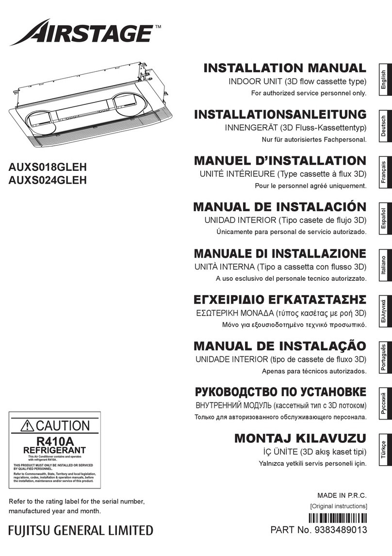
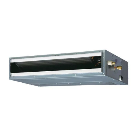
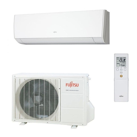
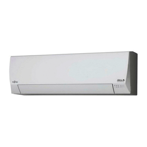
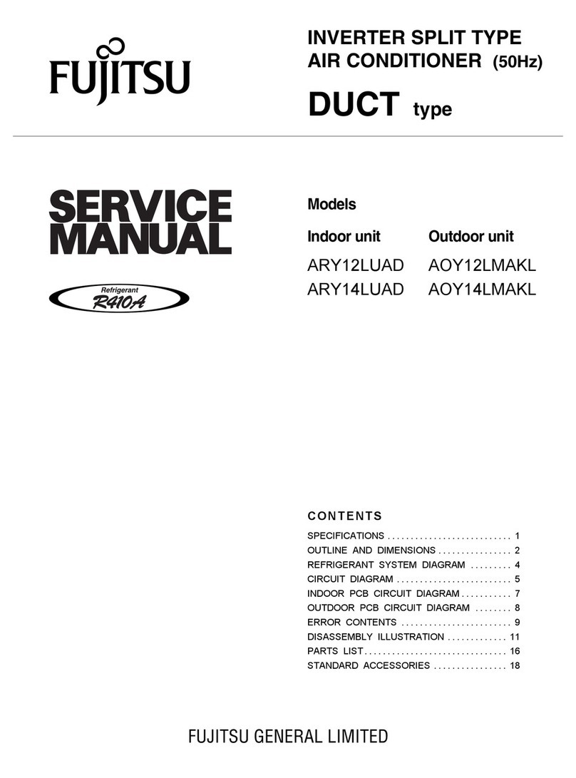
  9. Fujitsu AS G07KGTB Series Original operating manual

Fujitsu AS G07KGTB Series Original operating manual

Models Indoor unit Outdoor unit
AS* G07KGTB
AS* G09KGTB
AS* G12KGTB
AS* G14KGTB
AS* G07KMTB
AS* G09KMTB
AS* G12KMTB
AS* G14KMTB
AS*G07KETA (-B)
AS*G09KETA (-B)
AS*G12KETA (-B)
AS*G14KETA (-B)
ARXG07KSLAP
ARXG09KSLAP
ARXG12KSLAP
ARXG14KSLAP
ARXG07KLLAP
ARXG09KLLAP
ARXG12KLLAP
ARXG14KLLAP
AUXG07KVLA
AUXG09KVLA
AUXG12KVLA
AUXG14KVLA
AO* G14KBTA2
AO* G18KBTA2
Indoor unit Outdoor unit
RSG07KGTB
RSG09KGTB
RSG12KGTB
RSG14KGTB
RSG07KMTB
RSG09KMTB
RSG12KMTB
RSG14KMTB
RSG07KETA (-B)
RSG09KETA (-B)
RSG12KETA (-B)
RSG14KETA (-B)
RDG07KSLAP
RDG09KSLAP
RDG12KSLAP
RDG14KSLAP
RDG07KLLAP
RDG09KLLAP
RDG12KLLAP
RDG14KLLAP
RCG07KVLA
RCG09KVLA
RCG12KVLA
RCG14KVLA
ROG14KBTA2
ROG18KBTA2
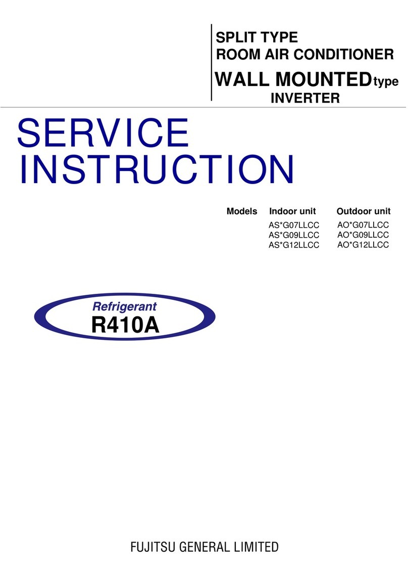
SERVICE
INSTRUCTION
SPLIT TYPE
ROOM AIR CONDITIONER
Compact Cassette / Slim Duct /
Mini Duct / Wall Mounted
INVERTER MULTI
2 . TROUBLE SHOOTING
INVERTER (MULTI )
Compact Cassette / Slim Duct /
Mini Duct / Wall Mounted
Indoor Room Thermistor Error
Wired Remote Controller
Communication Error
Error Contents Trouble
shooting
02-01
2 ERROR DISPLAY
2-1 INDOOR UNIT AND WIRED REMOTE CONTROLLER DISPLAY
Serial Communication Error
External communication Error
Indoor unit capacity Error
Combination Error
Indoor unit address setting Error
Connection unit number Error
(Indoor unit Wired remote controller Error)
Indoor Unit Fan Motor Error
Indoor Heat Ex. Thermistor Error
Drain pump Error
1,2
3
4
6
7
8
10
18
12
13
14
15
16
17
19
21
20
22
24
25
Trip terminal L Error
Error
Code Error Contents Trouble
shooting
Error
Code
11
12
39
41
Manual auto switch Error 11
35
42
51
53
63
18
522
23
29
26
33
3A
62
64
65
71
73
74
Indoor unit power supply Error
for fan motor
Indoor unit Communication circuit
(wired remote controller) Error
Indoor unit motor electricity
consumption detection Error
932
Indoor unit PCB model
information Error
Inverter Error
Outdoor unit main PCB model
information error
27
29
30
31
32
33
84
94
95
97
99
A1
Trip detection
Discharge Thermistor Error
23
72
Compressor Thermistor Error
Outdoor Thermistor Error
26-1
76
2-way Valve Thermistor Error
26-2
76
3-way Valve Thermistor Error
Current sensor Error
Heat Ex. Outlet / Middle
Thermistor Error
Compressor rotor position
detection Error
Outdoor Unit Fan Motor Error
4-way Valve Error
Discharge Temp. Error
PFC circuit Error
1. If an error occurs, an error icon appears on the “Monitor mode screen”.
Touch the [Status] on the “Monitor mode screen”.The “Status” screen is displayed.
2. Touch the [Error Information] on the “Status”screen. The “Error Information”screen is displayed.
(If there are no errors, the [Error Information] will not be displayed.)
3. 2-digit numbers correspond to the error code in the table below. Touch the [Next page]
(or [Previous page]) to switch to other connected indoor units.
For the details of the indoor unit or outdoor unit error , refer to the error codes in each installation manual
Mode Set Temp.
Fri 10:00AM
Menu Monitor Back
Page 1/ 4 Page 1/ 5
Air Flow Direction
Economy
VT
Individual Error Code
Address
[ 1 ] [ 02 01 ]
[ 14 . 15, 41 . 44 ]
[ ]
[ Off ]
Next
Page
Next
Page
Error
Information
Status
Status
Error Information
Fan
!
1. 2. 3.
Check the Error code on the wired remote controller (Remote controller *Option)
Check the Error LED display on the Indoor unit (IR Receiver *Option )
1. Check ECONOMY (Green) LED Blinking, it means the Error on the system. (Not brinking: No Error)
2. Count OPERATION (Green) LED blinks: The number of blinking means the first digit of Error code.
3. Count TIMER (Orange) LED blinks: The number of blinking means the second digit of Error code.
Ex.) ECONOMY: Blinking continuous / OPERATION: 4 times / TIMER: 1 time Indoor Room Thermistor Error
02-02
Trouble shooting 1
OUTDOOR UNIT Error Method:
Detective Actuators: Detective details:
Forecast of Cause:
OK
Indicate or Display:
YESYES
NO
OK
1. Connection failure 2. External cause 3. Main PCB failure 4. Outdoor unit fan motor failure
Check Point 1-1 : Reset the power and operate
Does Error indication show again?
Check Point 1-2: Check external cause such as noise
Check the complete insulation of the grounding.
Check if there is any equipment that causes harmonic wave
near the power cable (Neon light bulb or any electronic
equipment which causes harmonic wave).
Check Point 2 : Check Connection
Check any loose or removed connection line of
Indoor unit and Outdoor unit.
>> If there is an abnormal condition, correct it by
referring to Installation Manual or Data &
Technical Manual.
Check Point 3 : Check the voltage of power supply
Check the voltage of power supply
>> Check if AC198V (AC220V -10%) - 264V (AC240V +10%) appears
at Outdoor Unit Terminal L - N.
Check Point 4 : Check Serial Signal (Reverse Transfer Signal)
Check Serial Signal (Reverse Transfer Signal)
>> Check if Indicated value swings between AC90V and AC270V at Outdoor Unit Terminal 1 - 3.
>> If it is abnormal, Check Outdoor unit fan motor (PARTS INFORMATION 5)
>> If Outdoor fan motor is abnormal, replace Outdoor unit fan motor and Main PCB.
>> If Outdoor fan motor is normal, replace Main PCB.
When the indoor unit cannot receive the serial signal from Outdoor unit
more than 2minutes after power ON, or the indoor unit cannot receive
the serial signal more than 15seconds during normal operation.
2-2 TROUBLESHOOTING WITH ERROR CODE
Serial communication error
(Serial Reverse Transfer Error)
Outdoor unit Main PCB
Outdoor unit fan motor
Error code : 11 Outdoor unit : No indication
AC
AC
+
-
AC
1
2
3
RED
WHITE
BLACK
02-03
Trouble shooting 2
INDOOR UNIT Error Method:
Detective Actuators: Detective details:
Forecast of Cause:
OK
Indicate or Display:
YESYES
NO
+
-
OK
1. Connection failure 2. External cause 3. Controller PCB failure
Check Point 1-1 : Reset the power and operate
Does Error indication show again?
Check Point 1-2: Check external cause such as noise
Check if the ground connection is proper.
Check if there is any equipment that causes harmonic wave
near the power cable (Neon light bulb or any electronic
equipment which causes harmonic wave).
Check Point 2 : Check Connection
Check any loose or removed connection line of
Indoor unit and Outdoor unit.
Check connection condition in control unit.
(If there is loose connector, open cable or mis-wiring)
>> If there is an abnormal condition, correct it by
referring to Installation Manual or Data &
Technical Manual.
Check Point 3 : Check the voltage of power supply
Check the voltage of power supply
>> Check if AC198V (AC220V -10%) - 264V (AC240V +10%) appears
at Outdoor Unit Terminal L - N.
Check Point 4 : Check Serial Signal (Forward Transfer Signal)
Check Serial Signal (Forward Transfer Signal)
>> Check if indicated value swings berween AC30v and AC130V at outdoor unit terminal 2 - 3.
>> If it is abnormal, replace Controller PCB.
When the outdoor unit cannot properly receive the serial signal from
indoor unit for 10 seconds or more.
Serial communication error
(Serial Forward Transfer Error)
Indoor unit Controller PCB
Error code : 11 Outdoor unit : No indication
AC
AC
AC
1
2
3
RED
WHITE
BLACK
02-04
Trouble shooting 3
INDOOR UNIT Error Method:
Detective Actuators: Detective details:
Forecast of Cause:
OK
Indicate or Display:
1. Connection failure 2. Wired Remote Controller failure 3. Controller PCB failure
Check Point 1 : Check the connection of terminal
After turning off the power.
Check & correct the followings.
Upon receiving the signal more than 1 time from Wired Remote or other Indoor
unit, but the same signal has not been received more than 1 minute
(3 Wire type), 2.5 minute (2 Wire type)
Wired Remote Controller
Communication Error
Indoor unit Controller PCB
Wired Remote Controller
Error code : 12 Outdoor unit : No indication
Check the connection of terminal berween Wired Remote Controller and indoor unit,
and check if there is a disconnection of the cable.
Check Point 1-2 : Check Wired Remote Controller and Controller PCB
Check Voltage at CN300 of Controller PCB. (Terminal 1-3, Terminal 1-2)
(Power supply for the Remote Control)
Check Point 2 : Wire installation Wrong RCgroup setting
Wrong wire connection in RCgroup (Please refer to the installation manual)
The number of connecting indoor unit and Remote controller in one RCgroup were less than 16 units.
Check if controller PCB damage.
Change controller PCB and check the Error after setting remote controller address.
Check Point 2-1 : Check Indoor unit controller PCB
Check Voltage at CN300 (Terminal 1-2) of UTY-TWRXZ2 (Communication kit).
(Power supply to Remote control)
For AS* G __ KGTB
>> If it is DC12V, Remote control is failure. (Controller PCB is normal) >> Replace Remote control
>> If it is DC 0V, Controller PCB is failure. (Check Remote control once again) >> Replace Controller PCB
Check Voltage at CNC01 (Terminal 1-3) of UTY-TWBXF2 (Communication kit).
(Power supply to Remote control)
For AS* G __ KMTB
For AR type
For AU type
>> If it is DC13V, Remote control is failure. (Controller PCB is normal) >> Replace Remote control
>> If it is DC 0V, Controller PCB is failure. (Check Remote control once again) >> Replace Controller PCB
>> If it is DC13V, Remote control is failure. (Controller PCB is normal) >> Replace Remote control
>> If it is DC 0V, Controller PCB is failure. (Check Remote control once again) >> Replace Controller PCB
Check Voltage at CN14 of Controller PCB. (Terminal 1-3, Terminal 1-2)
(Power supply for the Remote Control)
Upon correcting the removed connector or mis-wiring, reset the power.
>> If it is DC12V, Remote control is failure. (Controller PCB is normal) >> Replace Remote control
>> If it is DC 0V, Controller PCB is failure. (Check Remote control once again) >> Replace Controller PCB
DC
Trouble shooting 4
INDOOR UNIT Error Method:
External communication error
Detective Actuators: Detective details:
Forecast of Cause :
OKOK
External communication error
Check any loose or removed connection of between the controller PCB to the external I/OPCB
>>If there is an abnormal condition, correct it by refer to installation manual or
the technical manual.
Check the condition condtion on the external I/O PCB and the controller PCB
(If there is loose connector, open cable or mis-wiring)
After receiving a signal from the external I/O PCB,
the same a signal has not been received for 15sec
1. Connection failure 2. External I/O PCB failure 3. Controller PCB failure
Check Point 1 : Check the connection
Check Point 2: Replace external I/O PCB
If Check Point 1 do not improve the symptom, change External I/O PCB.
OKOK
Check Point 3: Replace Controller PCB
If Check Point 2 do not improve the symptom, change Controller PCB.
Indicate or Display:
Error code : 18
02-05
Outdoor unit : No indication
Trouble shooting 5
OUTDOOR UNIT Error Method:
Indoor unit capacity error
Detective Actuators: Detective details:
Forecast of Cause :
OKOK
All indoor units The total capacity of the indoor units if it is install beyond.
1. The selection of indoor units is incorrect 2. Main PCB(Outdoor unit) failure
Indicate or Display:
Error code : 22
02-06
Outdoor unit : No indication
Check Point 1 : Check the total capacity of indoor unit
Check the total capacity of the connected indoor units.
>> If abnormal condition is found, correct it by referring
to Installation Manual or Design & Technical Manual.
Check Point 2 : Replace Main PCB
If Check Point 1 do not improve the symptom, replace Main PCB of Outdoor unit.
Trouble shooting 6
INDOOR UNIT Error Method:
Detective Actuators: Detective details:
The outdoor unit receives the serial signal of applied refrigerant
information from Indoor unit. When the refrigerant is R410a.
Forecast of Cause:
OK
Combination error
Indoor unit
1. The selection of indoor units is incorrect
Check Point 1 : Check the type of indoor unit
Check the type of the connected indoor unit.
>> If abnormal condition is found, correct it.
Check Point 2 : Replace Main PCB
If Check Point 1 do not improve the symptom, replace Main PCB of Outdoor unit.
Indicate or Display:
Error code : 23
02-07
Outdoor unit : No indication
Detective Actuators:
Wired remote controller ( 2-Wire )
Indoor unit Controller PCB circuit
Detective details:
When the address number set by auto setting and manual setting are
mixed in one RC group.
When the duplicated address number exists in one RC group.
Check Point 3 : Check Indoor unit controller PCB
Forecast of Cause :
1. Wrong wiring of RCgroup 2. Wrong remote address setting 3. Indoor unit controller PCB failure
4. Remote controller failure
Check Point 1 : Wire installation
Wrong wire connection in RCgroup (Please refer to the installation manual)
Change controller PCB and check the Error after setting remote controller address
Check if controller PCB damage
Check Point 2 : Wrong RCgroup setting
The given address number by auto setting (00) and the manual set number (Except 00)
were not existing in one RCG.
The remote controller address setting by U.I. were not existing same address.
The duplicated address number is not existing in one RCgroup
Trouble shooting 7
INDOOR UNIT Error Method:
Indoor unit address setting error
Indicate or Display:
Error code : 26
02-08
Outdoor unit : No indication
OK
OK
02-09
Trouble shooting 8
INDOOR UNIT Error Method:
Connection unit number error (Indoor
unit in Wired remote controller system)
Detective Actuators:
Wired remote controller ( 2-Wire )
Indoor unit Controller PCB circuit
Detective details:
When the number of connecting indoor units are out of specified rule.
Forecast of Cause :
1. Wrong wiring / Number of I.U, RC in RCgroup 2. Indoor unit controller PCB defective
Check Point 1 : Wire installation
Wrong number of connecting indoor unit
Check Point 2 : Check Indoor unit controller PCB
Check if controller PCB damage
Check if controller PCB and check the Error after setting remote controller address
Indicate or Display:
Error code : 29 Outdoor unit : No indication
OK
Detective Actuators: Detective details:
Forecast of Cause:
Check Point 3 : Replace Controller PCB
Check Point 2 :
Check Indoor unit electric components
YESYES
NO
Trouble shooting 9
INDOOR UNIT Error Method:
Indoor unit PCB
model information error
Indoor unit Controller PCB
1. External cause 2. Defective connection of electric components 3. Controller PCB failure
Check Point 1-1 : Reset Power Supply and operate
Does Error indication show again?
Check Point 1-2 :
Check external cause such as noise
Check if the ground connection is proper.
Check if there is any equipment that causes harmonic wave
near the power cable (Neon light bulb or any electronic
equipment which causes harmonic wave).
Note : EEPROM
EEPROM(Electronically Erasable and
Programmable Read Only Memory) is a non-
volatile memory which keeps memorized
information even if power is turned off.
It can change the contents electronically.
To change the contents, it uses higher voltage
than normal, and it can not change a partial
contents. (Rewriting shall be done upon
erasing the all contents.)
There is a limit in a number of rewriting.
Change Controller PCB.
Check all connectors.
(loose connector or incorrect wiring)
Check any shortage or corrosion on PCB.
When power is on and there is some below case.
1. When model information of EEPROM is incorrect.
2. When the access to EEPROM failed.
Indicate or Display:
Error code : 32
02-10
Outdoor unit : No indication
Detective Actuators: Detective details:
Forecast of Cause:
Trouble shooting 10
INDOOR UNIT Error Method:
Indoor unit fan motor
Indoor unit Controller PCB circuit
Indoor unit motor electricity
consumption detection error
1. Fan motor failure 2. Controller PCB failure
When the voltage value or the current value of the motor go beyond the limits.
Indicate or Display:
Error code : 33
02-11
Check Point 1 : Check rotation of Fan
Check Point 2 : Check ambient temp. around motor
OK
OK
OK
Rotate the fan by hand when operation is off.
(Check if fan is caught, dropped off or locked motor)
>>If Fan or Bearing is abnormal, replace It.
Check excessively high temperature around the motor.
(if there is any surrounding equipment that causes heat)
>>Upon the temperature coming down, restart operation.
Check Point 4 : Replace Controller PCB
If Check Point 1- 3 do not improve the symptom, replace Controller PCB.
Check Point 3 : Check Indoor unit fan motor
Check Indoor unit fan motor. (PARTS INFORMATION 4)
>>if Indoor unit fan motor is abnormal, replace Indoor unit fan motor.
Outdoor unit : No indication
Detective Actuators: Detective details:
Forecast of Cause:
Trouble shooting 11
INDOOR UNIT Error Method:
Manual auto switch Error
Indicate or Display:
Error code : 35
02-12
OK
Outdoor unit : No indication
Indoor unit Controller PCB
Indicator PCB
Manual auto switch
When the Manual Auto Switch becomes ON
for consecutive 60 or more seconds.
1. Manual auto switch failure 2. Controller PCB and Indicator PCB failure
Check Point 1 : Check the Manual auto switch
Check if Manual auto switch is kept pressed.
Check Point 2 : Replace Controller PCB
If Check Point 1 do not improve the symptom,
change Controller PCB and Indicator PCB.
Check ON/OFF switching operation by using a meter.
>>If Manual auto switch is disabled (on/off switching), replace it.
Trouble shooting 12
INDOOR UNIT Error Method:
Detective Actuators: Detective details:
Forecast of Cause :
Indoor unit power supply error
for fan motor
Indoor unit Power Supply PCB When a momentary power cut off.
When do not start fan motor.
1. External cause 2. Connection of connector failure 3. Power Supply PCB failure
Check Point 3 : Replace Power supply PCB
If Check Point 1, 2 do not improve the symptom, replace Power supply PCB.
OK
OK
Check Point 2 : Check connection of Connector
Check if connector is removed.
Check erroneous connection.
Check if cable is open.
>>Upon correcting the removed connector or mis-wiring, reset the power.
Check Point 1 : Check external cause at lndoor and Outdoor (Voltage drop or Noise)
Instant drop : Check if there is a large load electric apparatus in the same circuit.
Momentary power failure : Check if there is a defective contact or leak current in the power supply circuit.
Noise : Check if there is any equipment causing harmonic wave near electric line.
(Neon bulb or electric equipment that may cause harmonic wave)
Check the complete insulation of grounding.
Indicate or Display:
Error code : 39
02-13
Outdoor unit : No indication
Trouble shooting 13
INDOOR UNIT Error Method:
Indoor unit Communication circuit
(wired remote controller) error
Detective Actuators:
Indoor unit Controller PCB circuit
Detective details:
OK
Detect the communication error of microcomputer and communication PCB.
Check Point 2 : Replace the communication PCB
OK
Forecast of Cause :
1.Communication PCB defective 2. Indoor unit controller PCB defective
Check Point 1 : Check the connection of terminal
Indoor unit - Check the connection the communication PCB and the controller PCB
After turning off the power supply, check & correct the followings
If the Check point 1 is ok, replace the communication PCB
Indicate or Display:
Error code : 3A
02-14
Check Point 3 : Replace the controller PCB
If condition is doesn’t change, replace the controller PCB
Outdoor unit : No indication
Detective Actuators:
Indoor unit Controller PCB Circuit
Indoor Temperature Thermistor
Detective details:
Indoor unit thermistor is open or short is detected always.
Forecast of Cause :
1. Connector failure connection 2. Thermistor failure 3. Controller PCB failure
Check Point 2 : Remove connector and check Thermistor resistance value
Thermistor Characteristics(Rough value)
If Thermistor is either open or shorted, replace it and reset the power.
Check Point 1 : Check connection of Connector
Check if connector is loose or removed
Check erroneous connection
Check if thermistor cable is open
>>Reset Power when reinstalling due to removed connector or incorrect wiring.
OK
OK
Trouble shooting 14
INDOOR UNIT Error Method:
Indoor Room Thermistor Error
Indicate or Display:
02-15
Error code : 41 Outdoor unit : No indication
Resistance value (k )
Temperature (°C )
Temperature (°C ) -10 -5 0 5 10 15 20 25
30 35 40 45
Resistance value (k ) 58.2 44.0 33.6 25.9 20.2 15.8 12.5 10.0
8.0 6.5 5.3 4.3
Check Point 3 : Check Voltage of Controller PCB (DC 5.0V)
Make sure circuit diagram of each indoor unit and check terminal voltage at Thermistor (DC5.0V)
If the voltage does not appear, replace Controller PCB and execute the check operation again.
BLACK
BLACK
1
2
3
1
2
3
4 4
H/E Thermistor
Room Temp. Thermistor
CN1
DC
BLACK
BLACK
BLACK
BLACK
1
2
3
1
2
3
4 4
H/E Thermistor
Room Temp. Thermistor
CN4 BLACK
BLACK
BLACK
BLACK
GRAY
GRAY
1
2
3
1
2
3
H/E Thermistor
Room Temp. Thermistor
1
2
1
2
CN32
GRAY
GRAY
1
2
3
1
2
3
CN8
BLACK
BLACK
Room Temp. Thermistor
1
2
1
2
CN8
H/E Thermistor
CN6
For AS* G __ KGTB For AS* G __ KMTB
For AR type For AU type
Detective Actuators:
Indoor unit Controller PCB Circuit
Heat Exchanger (MID) Thermistor
Detective details:
Indoor unit thermistor is open or short is detected always.
Forecast of Cause :
1. Connector failure connection 2. Thermistor failure 3. Controller PCB failure
Check Point 2 : Remove connector and check Thermistor resistance value
Thermistor Characteristics(Rough value)
If Thermistor is either open or shorted, replace it and reset the power.
Check Point 1 : Check connection of Connector
Check if connector is loose or removed
Check erroneous connection
Check if thermistor cable is open
>>Reset Power when reinstalling due to removed connector or incorrect wiring.
OK
OK
Trouble shooting 15
INDOOR UNIT Error Method:
Indoor Heat Ex. Thermistor Error
Indicate or Display:
02-16
Error code : 42 Outdoor unit : No indication
Resistance value (k )
Temperature (°C )
Temperature (°C )
Resistance value (k )
-30 -25 -20 -15 -10 -5 0 5 10 15
20 25 30 35 40 45 50 55 60 65
1131.9 804.5 579.6 422.9 312.3 233.2 176.0 134.2 103.3 80.3
62.9 49.7 39.6 31.7 25.6 20.8 17.1 14.1 11.6 9.7
Resistance value (k )
Temperature (°C )
Temperature (°C )
Resistance value (k )
-30 -25 -20 -15 -10 -5 0 5 10 15
20 25 30 35 40 45 50 55 60 65
1013.1 729.1 531.5 392.3 292.9 221.1 168.6 129.8 100.9 79.1
62.5 49.8 40.0 32.4 26.3 21.6 17.8 14.8 12.3 10.3
Check Point 3 : Check Voltage of Controller PCB (DC 5.0V)
Make sure circuit diagram of each indoor unit and check terminal voltage at Thermistor (DC5.0V)
If the voltage does not appear, replace Controller PCB and execute the check operation again.
BLACK
BLACK
1
2
3
1
2
3
4 4
H/E Thermistor
Room Temp. Thermistor
CN1
DC
BLACK
BLACK
BLACK
BLACK
1
2
3
1
2
3
4 4
H/E Thermistor
Room Temp. Thermistor
CN4 BLACK
BLACK
BLACK
BLACK
GRAY
GRAY
1
2
3
1
2
3
H/E Thermistor
Room Temp. Thermistor
1
2
1
2
CN32
GRAY
GRAY
1
2
3
1
2
3
CN8
BLACK
BLACK
Room Temp. Thermistor
1
2
1
2
CN8
H/E Thermistor
CN6
For AS* G __ KGTB For AS* G __ KMTB
For AR type
For AS type
For AR / AU type
For AU type
02-17
Trouble shooting 16
INDOOR UNIT Error Method:
Indoor Unit Fan Motor Error
Detective Actuators: Detective details:
Forecast of Cause:
Check Point 1 : Check rotation of Fan
Check Point 2 : Check ambient temp. around motor
OK
OK
OK
Indoor unit Controller PCB
Indoor unit Power Supply PCB
(For AR / AU type)
Indoor unit fan motor
1. Fan rotation failure 2. Fan motor winding open 3. Motor protection by surrounding temperature rise
4. Controller PCB failure 5. Power Supply PCB failure 6. Indoor unit fan motor failure
Rotate the fan by hand when operation is off.
(Check if fan is caught, dropped off or locked motor)
>>If Fan or Bearing is abnormal, replace It.
Check excessively high temperature around the motor.
(if there is any surrounding equipment that causes heat)
>>Upon the temperature coming down, restart operation.
When the fan motor speed is less than 1/3 of the target fan speed
for 56 seconds.
When detect the 0 rpm for 56 seconds after fan motor started.
Check Point 4 : Replace Power Supply PCB (For AR / AU type)
If Check Point 1- 3 do not improve the symptom, replace Power Supply PCB.
Check Point 3 : Check Indoor unit fan motor
Check Indoor unit fan motor. (PARTS INFORMATION 4)
>>if Indoor unit fan motor is abnormal, replace Indoor unit fan motor.
OK
Check Point 5 : Replace Controller PCB
If Check Point 1- 4 do not improve the symptom, replace Controller PCB.
Indicate or Display:
Error code : 51 Outdoor unit : No indication
Trouble shooting 17
INDOOR UNIT Error Method:
Drain Pump Error
Detective Actuators:
Indoor unit Controller PCB Circuit
Float switch
Detective details:
When Float switch is ON for more than 3 minutes.
Check Point 1 : Check Float switch
Check operation of float switch. (any blocking by dust, etc.)
Remove Float switch and check ON/OFF switching operation
by using a meter.
>>If Float switch is abnormal, replace it.
ON OFF
OK
Forecast of Cause :
1. Float switch failure 2. Shorted connector/wire 3. Controller PCB failure
4. Drain pump failure 5. Hose clogging
Check Point 2 : Check Connector and Wire
Check loose contact of CN9 /shorted wire (pinched wire).
>>Replace Float switch if the wire is abnormal
OK
OK
OK
Check Point 3 : Check Drain hose
Check Drain hose .
>>If there is Hose clogging. Please clear the clog.
02-18
Indicate or Display:
Error code : 53 Outdoor unit : No indication
Check Point 4 : Replace Drain pump
If Check Point 1- 3 do not improve the symptom,
replace Drain pump.
Check Point 5 : Replace Controller PCB
If Check Point 4 do not improve the symptom,
replace Controller PCB.
For AR / AU type

This manual suits for next models

59

Other Fujitsu Air Conditioner manuals

Fujitsu ABY30TBAG User manual

Fujitsu

Fujitsu ABY30TBAG User manual

Fujitsu AS*G07LUCA Service manual

Fujitsu

Fujitsu AS*G07LUCA Service manual

Fujitsu Airstage ASYE07GACH User manual

Fujitsu

Fujitsu Airstage ASYE07GACH User manual

Fujitsu ARHF12LALU User manual

Fujitsu

Fujitsu ARHF12LALU User manual

Fujitsu RSG36KMTA User manual

Fujitsu

Fujitsu RSG36KMTA User manual

Fujitsu ARU24RGLX Service manual

Fujitsu

Fujitsu ARU24RGLX Service manual

Fujitsu Halcyon AUU18RGLX Service manual

Fujitsu

Fujitsu Halcyon AUU18RGLX Service manual

Fujitsu AB*14LBAJ Original operating manual

Fujitsu

Fujitsu AB*14LBAJ Original operating manual

Fujitsu KLWA Series User manual

Fujitsu

Fujitsu KLWA Series User manual

Fujitsu Inverter Halcyon ASU9RL User manual

Fujitsu

Fujitsu Inverter Halcyon ASU9RL User manual

Fujitsu Halcyon AWU36CX User manual

Fujitsu

Fujitsu Halcyon AWU36CX User manual

Fujitsu ASY50-KM User manual

Fujitsu

Fujitsu ASY50-KM User manual

Fujitsu ABU36RSLX User manual

Fujitsu

Fujitsu ABU36RSLX User manual

Fujitsu ARHF09LALU User manual

Fujitsu

Fujitsu ARHF09LALU User manual

Fujitsu AST18AB User manual

Fujitsu

Fujitsu AST18AB User manual

Fujitsu ASY18LMA-W User manual

Fujitsu

Fujitsu ASY18LMA-W User manual

Fujitsu Airstage ARUM30TLAV2 User manual

Fujitsu

Fujitsu Airstage ARUM30TLAV2 User manual

Fujitsu ASU18RLB User manual

Fujitsu

Fujitsu ASU18RLB User manual

Fujitsu AOAG30LAT4 User manual

Fujitsu

Fujitsu AOAG30LAT4 User manual

Fujitsu AGYF09LAC User manual

Fujitsu

Fujitsu AGYF09LAC User manual

Fujitsu G07LMCA Original operating manual

Fujitsu

Fujitsu G07LMCA Original operating manual

Fujitsu AUU7RLF Service manual

Fujitsu

Fujitsu AUU7RLF Service manual

Fujitsu ASYG09LLCA User manual

Fujitsu

Fujitsu ASYG09LLCA User manual

Fujitsu ABHG18KRTA Service manual

Fujitsu

Fujitsu ABHG18KRTA Service manual

Popular Air Conditioner manuals by other brands

Samsung AFPCC052CA0 installation manual

Samsung

Samsung AFPCC052CA0 installation manual

Gree GWA2107BM operating instructions

Gree

Gree GWA2107BM operating instructions

Mitsubishi Electric MUZ-D-NA Series Service manual

Mitsubishi Electric

Mitsubishi Electric MUZ-D-NA Series Service manual

Mitsubishi Electric Mr.SLIM PSA-M-KA Series Operation manual

Mitsubishi Electric

Mitsubishi Electric Mr.SLIM PSA-M-KA Series Operation manual

Thermal Edge WF081 Series User's & technical manual

Thermal Edge

Thermal Edge WF081 Series User's & technical manual

Kaysun KPD-35 DN10 owner's manual

Kaysun

Kaysun KPD-35 DN10 owner's manual

Daikin vrv III -Q Series Operation manual

Daikin

Daikin vrv III -Q Series Operation manual

GE AKQ24DN Energy guide

GE

GE AKQ24DN Energy guide

Domo DO190A Instruction booklet

Domo

Domo DO190A Instruction booklet

Gree GWH09MA-A3DNC5A owner's manual

Gree

Gree GWH09MA-A3DNC5A owner's manual

Carrier 42KY Installation, operation and maintenance instructions

Carrier

Carrier 42KY Installation, operation and maintenance instructions

Mitsubishi Heavy Industries FDT71VNXVD Service manual

Mitsubishi Heavy Industries

Mitsubishi Heavy Industries FDT71VNXVD Service manual

Carrier 50GL 024-060 manual

Carrier

Carrier 50GL 024-060 manual

Soleus Air GH-PAC-10E5 operating instructions

Soleus Air

Soleus Air GH-PAC-10E5 operating instructions

Ouellet PUD09KCH23S owner's manual

Ouellet

Ouellet PUD09KCH23S owner's manual

Daikin RX-W Series Service manual

Daikin

Daikin RX-W Series Service manual

Danby DAC060BBCWDB Owner's use and care guide

Danby

Danby DAC060BBCWDB Owner's use and care guide

Hisense KG25YR1A Use and installation instruction

Hisense

Hisense KG25YR1A Use and installation instruction

manuals.online logo
manuals.online logoBrands
  • About & Mission
  • Contact us
  • Privacy Policy
  • Terms and Conditions

Copyright 2025 Manuals.Online. All Rights Reserved.