- (01-04) -
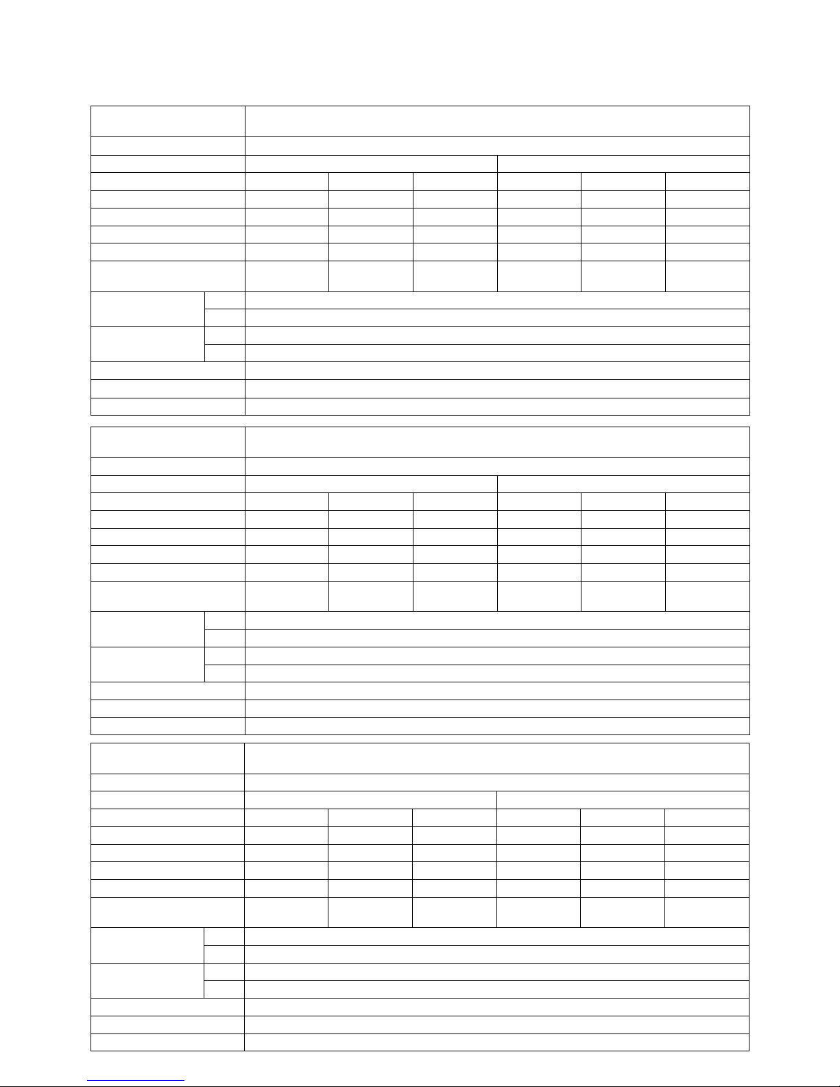
SPECIFICATIONS
Model
No.
Power
Source Notch Frequency
Heat Exchange Ventilation Normal Ventilation
Product
Weight
Input Current Air
Volume
External
Static
Pressure
Temperature
Exchange
Efciency
Enthalpy
Exchange
Efciency (%)
Noise Input Current Air
Volume
External
Static
Pressure
Noise
(Hz) (W) (A) (m3/h) (Pa) (%) Cooling Heating (dB) (W) (A) (m3/h) (Pa) (dB) (kg)
UTZ-
BD025B
220-240V
a.c.
Extra High
50 112-128 0.51-0.53 250 105 75 63 70 30.0-31.5 112-128 0.51-0.53 250 105 30.0-31.5
29
High
50 108-123 0.49-0.51 250 95 75 63 70 29.5-30.5 108-123 0.49-0.51 250 95 29.5-30.5
Low
50 87-96 0.40-0.41 190 45 77 65 72 23.5-26.5 87-96 0.40-0.41 190 45 23.5-26.5
This noise of the product is the value which was measured at the acoustic room. Actually, in the established condition, that undergo inuence
by the echoing of the room and so that become bigger than the display numerical value .
PERFORMANCE
Use conditions
Outdoor air conditions
Temperature range -10˚C ~ 40˚C
Relative humidity 85% or less
Indoor air conditions
Temperature range -10˚C ~ 40˚C
Relative humidity 85% or less
Installation requirements
Same as the indoor air conditions
*
Indoor air here means air in air-conditioned
living rooms.
Its use in refrigerators or other places
where temperature can uctuate greatly is
prohibited even if a temperature range is
acceptable.
Example Indoor air conditions
During cooling period
Temperature 27˚C
Relative humidity 50%
During heating period
Temperature 20˚C
Relative humidity 40%
• The Input, the current and the exchange
efficiency are values at the time of the
mentioned air volume.
• The noise level shall be measured 1.5m
below the center of the unit.
• The temperature exchange efficiency
averages that of when cooling and when
heating.
MOTOR
SPECIFICATIONS
Type 4 Poles open type
induction motor
Rating Cont.
Insulation Class class E
Temperature Rise under 75 K
Sorrounding Temperature
-10˚C ~ 40˚C
Insulation Resistance
over 1MΩ (by DC500V)
Withstand Voltage AC 1,500V for 1min
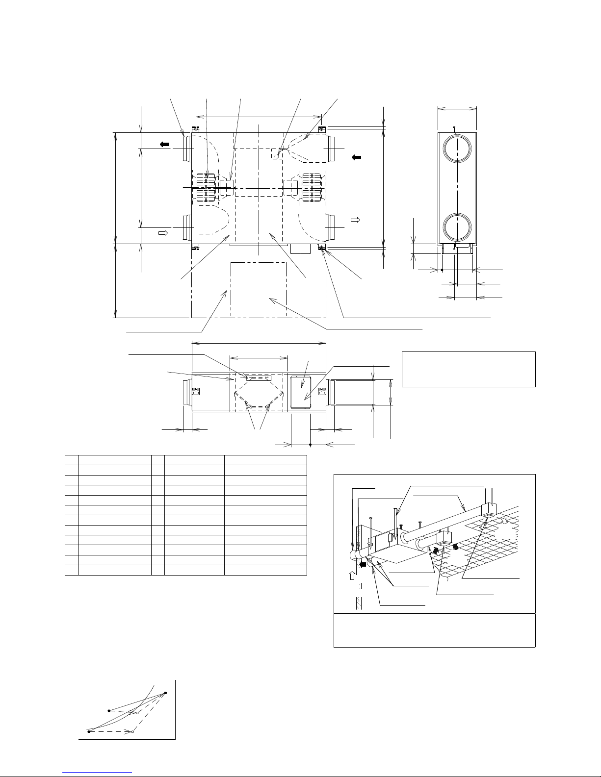
300
0 50 100 150 200 250 300 350
50
100
150
200
250
0 20 40 60 80 100 120 140 160 180 200 220
Air Volume (m3/h)
Air Volume (ft3/min)
External Static Pressure (Pa)
80
50
60
70
Exchange Efciency (%)
Duct resistance Curve
P-Q Curve
220 - 240V ~ 50HzEfciency Curve
T
e
m
pe
ra
t
u
r
e
E
nt
h
al
p
y
(i
n
h
e
a
t
i
n
g
)
E
nt
h
al
p
y
(i
n
c
o
o
li
n
g
)
Extra High
Equivalent pipe length
High
Low When friction coefcient of pipe (duct) : =0.02
100m
80
60
20
40