Labkotec SandSET-1000 12 VDC User manual

Labkotec Oy
Myllyhaantie 6
FI-33960 PIRKKALA
FINLAND
Tel.: +358 29 006 260
Fax: +358 29 006 1260 28.8.2019
E-mail: info@labkotec.fi D15649_E-2
Internet: www.labkotec.fi
1/13
Copyright © 2019 Labkotec Oy We reserve the right for changes without notice
SandSET-1000 12 VDC
Sludge Alarm Device
Installation and Operating Instructions

SandSET-1000 12 VDC Sludge Alarm Device D15649_E-2
Installation and Operating Instructions
Copyright © 2019 Labkotec Oy 2/13 We reserve the right for changes without notice
TABLE OF CONTENTS
1GENERAL............................................................................................................ 3
2INSTALLATION ................................................................................................... 4
2.1 SandSET-1000 12 VDC control unit............................................................ 4
2.2 SET/S2 sensor............................................................................................. 5
2.3 Cable joint .................................................................................................... 5
3OPERATION AND SETTINGS............................................................................ 6
3.1 Operation ..................................................................................................... 6
3.2 Factory settings............................................................................................ 7
4TROUBLE-SHOOTING ....................................................................................... 8
5REPAIR AND SERVICE...................................................................................... 9
6SAFETY INSTRUCTIONS................................................................................... 9
7TECHNICAL DATA............................................................................................ 10
8DECLARATION OF COMFORMITY ................................................................. 11
9DECLARATION OF COMFORMITY ................................................................. 12
10 DECLARATION OF CONFORMITY.................................................................. 13
SYMBOLS
Warning / Attention
Pay special attention to installations at explosive atmospheres
Device is protected by double or reinforced insulation

SandSET-1000 12 VDC Sludge Alarm Device D15649_E-2
Installation and Operating Instructions
Copyright © 2019 Labkotec Oy 3/13 We reserve the right for changes without notice
1 GENERAL
SandSET-1000 12 VDC is an alarm device to indicate the accumulation
of sludge or sand layer on the bottom of a well or tank. Typical
applications are sand and oil separators as well as settling tanks of
wastewater treatment plants and other wells or basins. Depending on
the order, the delivery consists of SandSET-1000 12 VDC control unit,
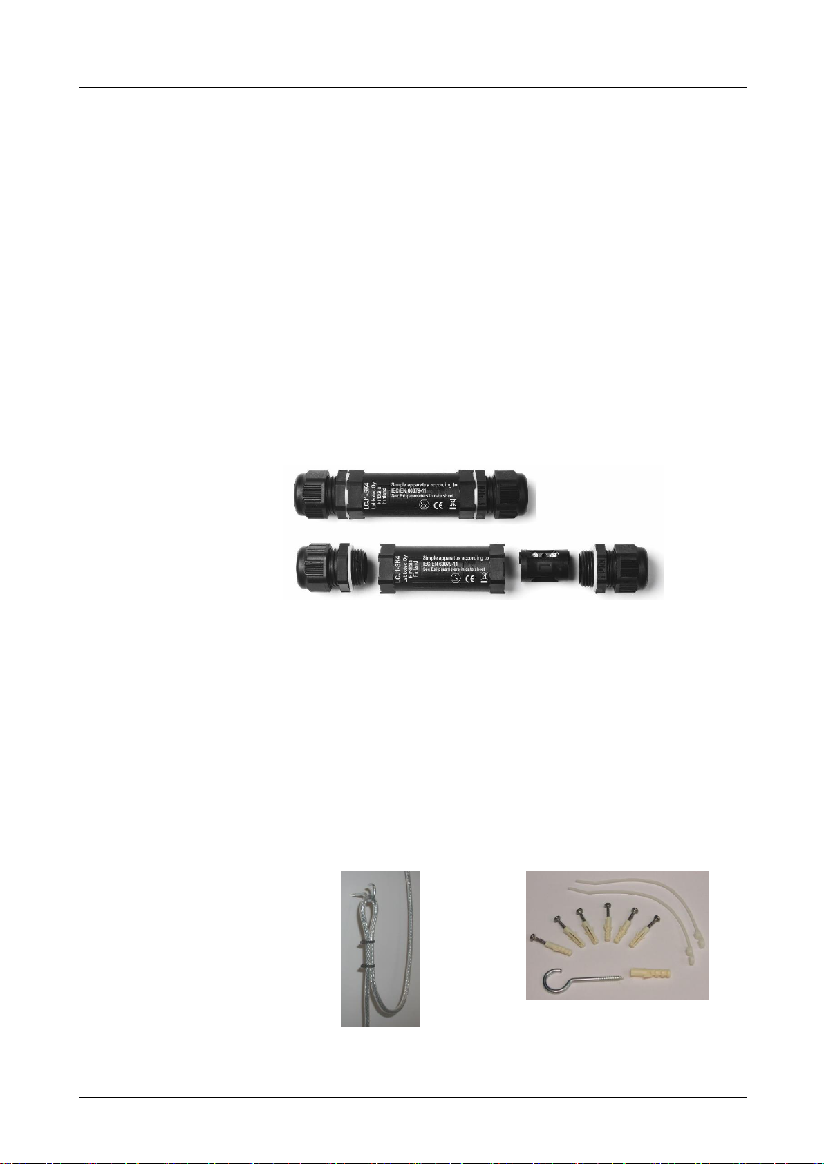
SET/S2 sensor, junction box and installation supplies.
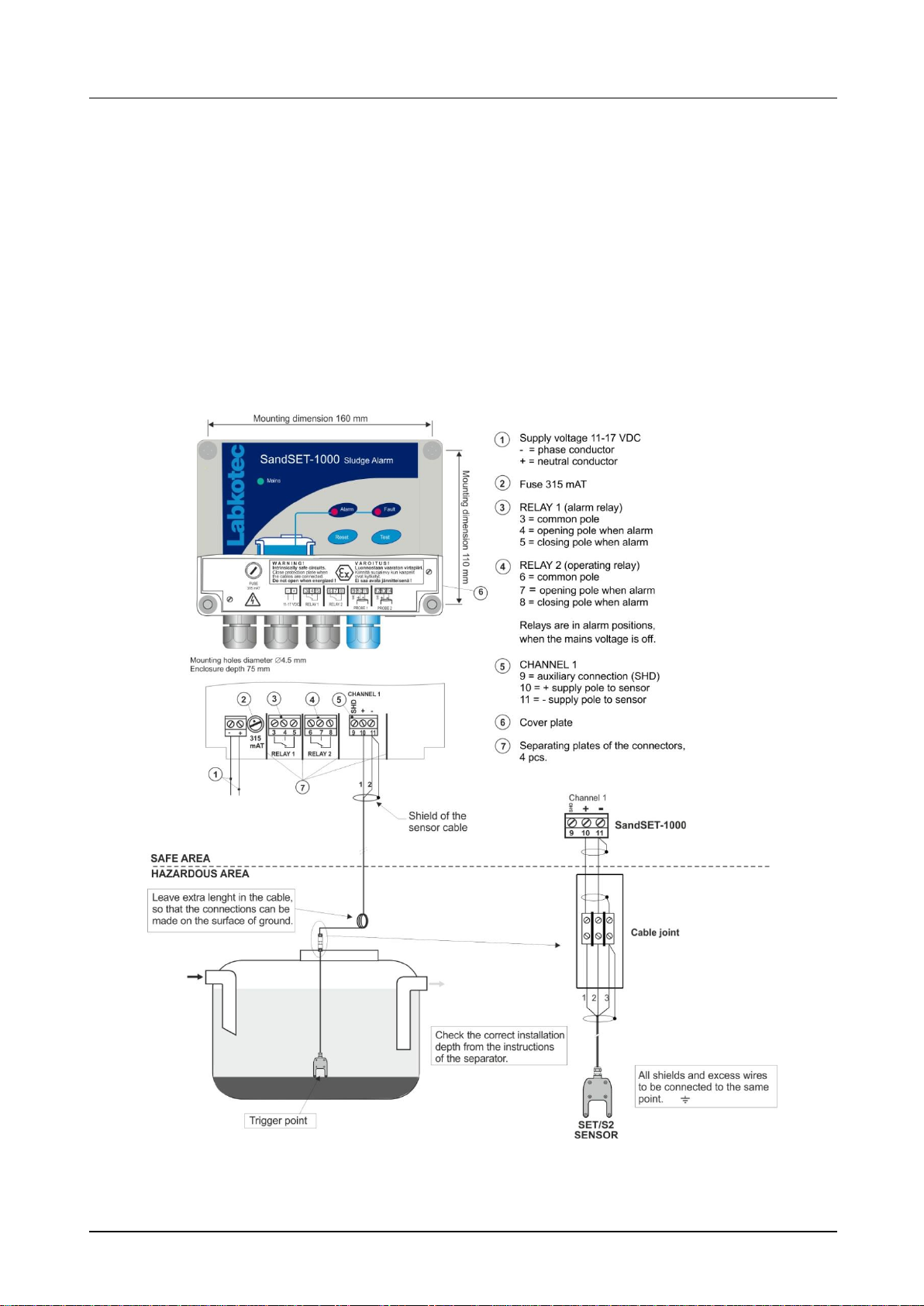
Figure 1. Sand separator alarm application
SET/S2 sensor is installed in the separator or tank and it gives an alarm
when the sludge reaches the sensor. The sensor is normally immersed
in water.
The principle of measurement is ultrasonic. When sludge, sand or other
solid particles accumulate between the two sensor heads, the signal
strength weakens, causing an alarm.
SET/S2 sensor can be installed in a zone 0, 1 or 2 potentially explosive
atmosphere but the control unit must be mounted in a safe area.
The LED indicators, push buttons and interfaces of the SandSET-1000
12 VDC control unit are described in figure 2.
Figure 2. SandSET-1000 12 VDC control unit - features

SandSET-1000 12 VDC Sludge Alarm Device D15649_E-2
Installation and Operating Instructions
Copyright © 2019 Labkotec Oy 4/13 We reserve the right for changes without notice
2 INSTALLATION
2.1 SandSET-1000 12 VDC control unit
SandSET-1000 12 VDC control unit can be wall-mounted. The
mounting holes are located in the base plate of the enclosure, beneath
the mounting holes of the front cover.
The connectors of the external conductors are isolated by separating
plates. The plates must not be removed. The plate covering the
connectors must be installed back after executing cable connections.
The cover of the enclosure must be tightened so, that the edges touch
the base frame. Only then do the push buttons function properly and
the enclosure is tight.
Before installation, please read the safety instructions in chapter 6 !
Kuva 3. SandSET-1000 12 VDC alarm device installation.

SandSET-1000 12 VDC Sludge Alarm Device D15649_E-2
Installation and Operating Instructions
Copyright © 2019 Labkotec Oy 5/13 We reserve the right for changes without notice
2.2 SET/S2 sensor
SET/S2 sensor should be installed as described in figure 3.
The sensor gives an alarm when the there is enough sand or sludge
accumulated between the two heads of the sensor. When the sludge
layer on the bottom of the separator or settling tank is pretty solid, the
correct installation depth can be adjusted based on the current level. In
case the level is not that clear, a tryout period of couple of days may be
useful.
Please check the instruction for correct installation depth also from the
instructions of the oil separator or other application.
The sensor can be mounted suspended from the ceiling of the tank by
its cable or installed with an installation conduit equipped with a ¾ inch
inner thread.
Variations in the water level in the well or basin must be taken into
account during installation. A false alarm results if the sensor is left
hanging in the air.
2.3 Cable joint
Fig. 4 Cable joint
Connections of the sensor cable inside the cable joint are explained in
figure 3. Cable shields and possible excess wires need to be connected
to the same point in galvanic contact.
Please make sure, that the sensor and cable between SandSET-1000
12 VDC control unit and the sensor do not exceed the maximum
allowed electrical parameters –see chapter 7 Technical data.
IP rating of the cable joint is IP68. Make sure, that the cable joint is
closed properly.
If the sensor cable must be extended and there is a need for
equipotential grounding, it should be done with the junction box LJB2.
The cabling between the SandSET-1000 12 VDC control unit and the
junction box should be done with a shielded twisted pair instrument
cable.
Fig. 5. Cable installation example
Fig. 6. Installation accessories

SandSET-1000 12 VDC Sludge Alarm Device D15649_E-2
Installation and Operating Instructions
Copyright © 2019 Labkotec Oy 6/13 We reserve the right for changes without notice
3 OPERATION AND SETTINGS
The SandSET-1000 12 VDC alarm device is initialized at the factory.
The operation of the alarm device should be checked always after the
installation.
Functionality test
1. Immerse the sensor into water. The device should be in normal mode.
2. Lift the sensor up in air or sink it into sludge. Alarm LED indicator
should be lit in 10 seconds. When LED is on should relays de-energize
and buzzer be on after selected delay (5 or 30 sec). See chapter 3.1 for
more details.
3. Immerse the sensor back into water. Alarm LED should go off in 10
seconds. Relays and buzzer should go back to the normal state after
delay (5 or 30 sec). Clean up the sensor if necessary before placing it
back into the separator.
A more detailed description of the operation is provided in chapter 3.1.
If the operation is not as described here, check the factory settings
(chapter 3.2.) or contact a representative of the manufacturer.
3.1 Operation
The operation of a factory-initialized SandSET-1000 12 VDC is
described in this chapter.
Normal mode –no alarms
The two heads of the SET/S2 sensor are totally immersed in water.
Mains LED indicator is on.
Other LED indicators are off.
Relays 1 and 2 are energized.
Alarm
The two heads of the SET/S2 sensor are immersed in sludge or sand.
Mains LED indicator is on.
Alarm LED indicator is on in 10 sec. (Delay of the sensor.)
Buzzer is on after 30…40 sec delay. (Delay of the control unit incl.)
Relays de-energize after 30…40 sec delay.
(Note. The same alarm takes place when SET/S2 sensor is in the air.)
After removal of an alarm (the two heads of the sensor are in water), the
Alarm LED indicator will be off. Relays will be energized and buzzer will
be off after a delay of 30…40 sec.
Fault alarm
Sensor cable break, short circuit or a broken sensor, i.e. too low or too
high sensor signal current.
Mains LED indicator is on.
Sensor circuit Fault LED indicator is on after 5 sec delay.
Buzzer is on after 5 sec delay.
The relays de-energize after 5 sec delay.
Reset of an alarm
When pressing the Reset push button.
Buzzer will go off.
Relay 1 energizes.
Relay 2 will stay de-energized until the actual alarm or fault is off.
The operational delay of SET/S2 prevents false alarms from occurring
when garbage or other obstacles, which weaken the measurement
signal momentarily, pass across the sensors heads.
Note! When testing the sensor operation in a separate vessel, the water
put into the vessel should stand for about 30 minutes before testing.
This prevents false alarms caused by the attachment of air bubbles on
the sensor heads.

SandSET-1000 12 VDC Sludge Alarm Device D15649_E-2
Installation and Operating Instructions
Copyright © 2019 Labkotec Oy 7/13 We reserve the right for changes without notice
TEST FUNCTION
Test function provides an artificial alarm, which can be used to test the
function of the SandSET-1000 12 VDC alarm device and the function
of other equipment, which are connected to SandSET-1000 12 VDC via
its relays.
Attention! Before pressing the Test button, make sure that the change
of relay status does not cause hazards elsewhere!
Normal situation
When pressing the Test push button:
Alarm and Fault LED indicators are immediately on.
Buzzer is immediately on.
Relays de-energize after 2 sec of continuous pressing.
When the Test push button is released:
LED indicators and buzzer go immediately off.
Relays energize immediately.
Alarm on
When pressing the Test push button:
Fault LED indicator is immediately on.
Alarm LED indicator remains on.
Buzzer remains on. If it has been reset earlier, it will return to be on.
If relay 1 was already reset, it will de-energize again after 2 sec. of
continuous pressing.
Test will not affect relay 2, because it is already in alarm status.
When the Test push button is released:
The device returns without delay to the preceding status.
Fault alarm on
When pressing the Test push button:
The device does not react to the test at all.
3.2 Factory settings
If the operation of SandSET-1000 12 VDC is not as described in the
previous chapter, check that the device settings are as in figure 7.
Change the settings according to the following instructions if needed.
The following tasks must only be executed by a person with proper
education and knowledge of Ex-i devices.
We recommend, that when altering the settings the mains voltage is off
or the device is initialized before the installation is executed.
Figure 7. Factory settings
The settings are made with switches (MODE and DELAY) and
potentiometer (SENSITIVITY) located in the upper printed circuit board,
and the jumper located in the lower board (figure 7). In figure 7, the

SandSET-1000 12 VDC Sludge Alarm Device D15649_E-2
Installation and Operating Instructions
Copyright © 2019 Labkotec Oy 8/13 We reserve the right for changes without notice
switches are as set in the factory.
Switch S2 is used to set the operational delay of the control unit.
When the switch is in low position, relays operate and buzzer is on after 5 seconds after the
sensor current has reached the trigger level, and if the level still remains on the same side of
the trigger level.
When the switch is in high position, the delay is 30 seconds.
Delays are operational in both directions (energizing, de-energizing). Alarm LED follows the
sensor current value and trigger level without delay. Fault alarm takes place after a fixed
delay of 5 sec.
4 TROUBLE-SHOOTING
Problem:
MAINS LED indicator is off
Possible reason:
Supply voltage is too low or the fuse is blown. Transformer or MAINS LED
indicator is faulty.
To do:
1. Check if the two pole mains switch is off.
2. Check the fuse.
3. Measure the voltage between poles - and +. It should be 11-17 VDC.
Problem:
No alarm when sensor in sludge or air, or the alarm will not go off
Possible reason:
The SENSITIVITY setting is wrong in the control unit (see figure 7).
To do:
1. Lift the sensor up in the air or immerse it into sludge and wait 10 seconds.
2. Turn the SENSITIVITY potentiometer slowly anticlockwise until the sensor gives
an alarm.
3. Immerse the sensor into water and wait until the alarm goes off. If the alarm
does not go off, turn the potentiometer slowly clockwise until the alarm goes off.
4. Lift the sensor up in the air or sink into sludge. The sensor should give an alarm
again.
Problem:
FAULT LED indicator is on
Possible reason:
Current in sensor circuit too low (cable break) or too high (cable in short circuit).
The sensor might also be broken.
To do:
1. Make sure, that the sensor cable has been connected correctly to the
SandSET-1000 12 VDC control unit. See instructions from chapter 2 or SET/S2
installation and Operating Instructions.
2. Measure the voltage separately between the poles 10 and 11. The voltages
should be between 10,3….11,8 V.
3. If the voltage is correct, measure the sensor current. Do as follows:
3.1 Disconnect sensor’s [+] wire from sensor connector (pole 10).
3.2 Measure short circuit current between [+] and [-] poles.
3.3 Connect mA-meter as in figure 8.
3.4 Connect the wire back to the connector.
If the problem can not be solved with the above instructions, please contact
Labkotec Oy’s local distributor or Labkotec Oy’s service.
Attention! If the sensor is located in an explosive atmosphere, the multimeter must
be Exi-approved!

SandSET-1000 12 VDC Sludge Alarm Device D15649_E-2
Installation and Operating Instructions
Copyright © 2019 Labkotec Oy 9/13 We reserve the right for changes without notice
SET/S2, channel 1
Poles 10 [+] ja 11 [-]
Shortcircuit
20 mA –24 mA
Sensor in the air
13 –14 mA
Sensor in sludge
12 –14 mA
Sensor in the water
6 –8 mA
Factory setting for
alarm point
approx. 11 mA
Figure 8. Sensor current measurement Table 1. Sensor currents
5 REPAIR AND SERVICE
The sensor should be cleaned and the operation should also be tested
when emptying the oil storage chamber or at least once every six
months. The easiest way to check the operation is to lift the sensor up
in the air and to put it back to the separator. The operation is described
in chapter 3.
For cleaning, a mild detergent (e.g. washing-up liquid) and a scrubbing
brush can be used.
The mains fuse (marked 315 mAT) can be changed to another glass
tube fuse 5 x 20 mm / 315 mAT complying IEC/EN 60127-2/3. Any other
repair and service works on the device may be carried out only by a
person who has received training in Ex-i devices and is authorized by
the manufacturer.
In case of queries, please contact Labkotec Oy’s service.
6 SAFETY INSTRUCTIONS
SandSET-1000 12 VDC control unit must not be installed in potentially
explosive atmosphere. Sensors connected to it may be installed in zone
0, 1 or 2 potentially explosive atmospheres.
In case of installations in explosive atmospheres the national
requirements and relevant standards as IEC/EN 560079-25 and/or
IEC/EN 60079-14 must be taken into account.
If electrostatic discharges can cause hazards in the operating
environment, the device must be connected into equipotential ground
according to requirements with regards to explosive atmospheres.
Equipotential grounding is made by connecting all conductive parts into
same potential e.g. at the cable junction box. Equipotential ground must
be earthed.
When executing service, inspection and repair in explosive atmosphere,
the rules in standards IEC/EN 60079-17 and IEC/EN 60079-19 about
instructions of Ex-devices must be obeyed.

SandSET-1000 12 VDC Sludge Alarm Device D15649_E-2
Installation and Operating Instructions
Copyright © 2019 Labkotec Oy 10/13 We reserve the right for changes without notice
7 TECHNICAL DATA
SandSET-1000 12 VDC control unit
Dimensions
175 mm x 125 mm x 75 mm (L x H x D)
Enclosure
IP 65, material polycarbonate
Ambient temperature
-25 ºC…+50 ºC
Supply voltage
11-17 VDC
Fuse 5 x 20 mm 315 mAT (IEC/EN
60127-2/3)
The device is not equipped with a mains
switch
Power consumption
Max. 1,2 VA.
Typical (no alarms) 0.9. VA.
Sensors
One Labkotec SET sensor (SET/S2)
Max. resistance of the
current loop between the
control unit and a sensor
75 Ω.
Relay outputs
Two potential-free relay outputs
250 V, 5 A, 100 VA
Operational delay 5 sec or 30 sec.
Relays de-energize at trigger point.
Operation mode selectable for increasing
or decreasing level.
Electrical safety
IEC/EN 61010-1, Class II , CAT II /
III
Insulation level
Sensor / Mains supply
voltage
375V (IEC/EN 60079-1)
EMC Emission
Immunity
IEC/EN 61000-6-3
IEC/EN 61000-6-2
Ex-classification
Special conditions (X)
ATEX
IECEx
II (1) G [Ex ia] IIC
(Ta = -25 C…+50 C)
VTT 04 ATEX 031X
IECEx VTT 10.0003X
Electrical parameters
Characteristic curve of the
output voltage is trapezoidal
See table 2.
Um = 23 V Uo = 14,7 V
Io = 55 mA Po = 297 mW
R = 404 Ω
Manufacturing year:
Please see the serial number
on the type plate
xxx x xxxxx xx YY x
where YY = manufacturing year
(e.g. 19 = 2019)
Due to non-linear characteristics of the sensor voltage, the interaction of
both, capacitance and inductance, must be taken into account. The
table below indicates the connecting values in explosion groups IIC and
IIB. In explosion group IIA the values of the group IIB can be applied.
Max. permissible value
Combined Co and Lo
Co
Lo
Co
Lo
II C
608nF
10 mH
568nF
458 nF
388 nF
328 nF
258 nF
0,15 mH
0,5 mH
1,0 mH
2,0 mH
5,0 mH
II B
3,84μF
30 mH
3,5 µF
3,1 µF
2,4 µF
1,9 µF
1,6 µF
0,15 mH
0,5 mH
1,0 mH
2,0 mH
5,0 mH
Lo/Ro= 116,5 µH/Ω (IIC) and 466 µH/Ω (IIB)
Table 2. SandSET-1000 12 VDC electrical parameters
SET/S2 sensor
Principle of operation
Ultrasonic
Enclosure
IP68
Materials: PP, PVC, AISI 304, AISI 316
and NBR rubber
Ambient temperature
0 ºC…+60 ºC
Supply voltage
Approx. 12 VDC from SET control unit
Cable
Fixed oil resistant PVC cable 3 x 0,5 mm2,
standard length 5 m.
Weight
Approx. 450 g
EMC Emission
Immunity
IEC/EN 61000-6-3
IEC/EN 61000-6-2
Ex-classification
ATEX
IECEx
II 1 G Ex ia IIB T5 Ga
VTT 07 ATEX 0051X
IECEx VTT 10.0002X
Electrical parameters
Ui = 16 V Ii = 80 mA
Pi= 320 mW Ci = 3 nF
Li = 80 μH
Manufacturing year:
Please see the serial
number on the type plate
xxx x xxxxx xx YY x
where YY = manufacturing year
(e.g. 19 = 2019)
Special conditions concerning Ex-classification (X):
- Ambient temperature -25 ºC…+60 ºC
- Shielded sensor cable and extra wires shall be connected to
equipotential ground
- If sensor cable have to be extended, please use LJB2-78-83 or
LJB3-78-83 junction box. The junction box shall also be
connected to equipotential ground.
Figure 9. Dimensional drawing of SET/S2 sensor

8 DECLARATION OF COMFORMITY

9 DECLARATION OF COMFORMITY

10 DECLARATION OF CONFORMITY
Table of contents
Popular Test Equipment manuals by other brands

Southwire
Southwire M500CX4 operating instructions

Apera Instruments
Apera Instruments GroStar GS3 Premium user manual

Tanaka
Tanaka BS2-80TS instruction manual

AMS
AMS SCRAM Quick reference guide

Fluke
Fluke 52801RJ9 user guide

Baker Instrument Company
Baker Instrument Company D6000 DIGITAL TROUBLESHOOTING PROCEDURES & FAULT LISTING