Fulgor Milano FOBQ 1000 G X User manual

FOBQ 1000 G X
FOBQ 1000 G MBK
FOBQ 803 G X
FOBQ 602 G X
FOBQ 601 TY G X
IT ISTRUZIONI PER L’INSTALLAZIONE E L’USO
EN INSTRUCTIONS FOR INSTALLATION AND USE
DE INSTALLATIONS- UND BEDIENUNGSANLEITUNG
ES
INSTRUCCIONES PARA LA INSTALACIÓN Y EL USO
BARBECUE DA INCASSO PER USO
DOMESTICO DA ESTERNO
BUILT-IN BARBECUE FOR HOME
OUTDOOR USE
EINBAU-GRILLKOFFER FÜR DEN
HAUSGEBRAUCH IM OUTDOOR-BEREICH
BARBECUE DE EMPOTRADO PARA USO
DOMÉSTICO EN EXTERIORES


EN
1
Congratulations
Congratulations and thanks for choosing our integrated
barbecue. We are confident that it will be a pleasure for you
to use our new barbecue. Before using the barbecue, we
recommend reading the entire user guide, which provides a
description of the barbecue and its functions. To avoid those
risks that are always present when using a gas appliance,
it is important to install it correctly and carefully read the
safety instructions in order to avoid misuse and hazards.
We recommend you keep this instruction booklet for future
reference and pass it to any subsequent owners. After
removing the barbecue from its packaging, check to see
that it is not damaged. If in doubt, do not use the appliance
and contact your nearest customer service centre.
Suggestion for the environment Disposal information
for users
• Most of the packaging material is recyclable. These
materials should be disposed of through a local recycling
centre or by putting them in appropriate collection
containers.
• If you want to discard the product, contact your local
authorities and ask about the correct method of disposal
TABLE OF CONTENTS PAGE
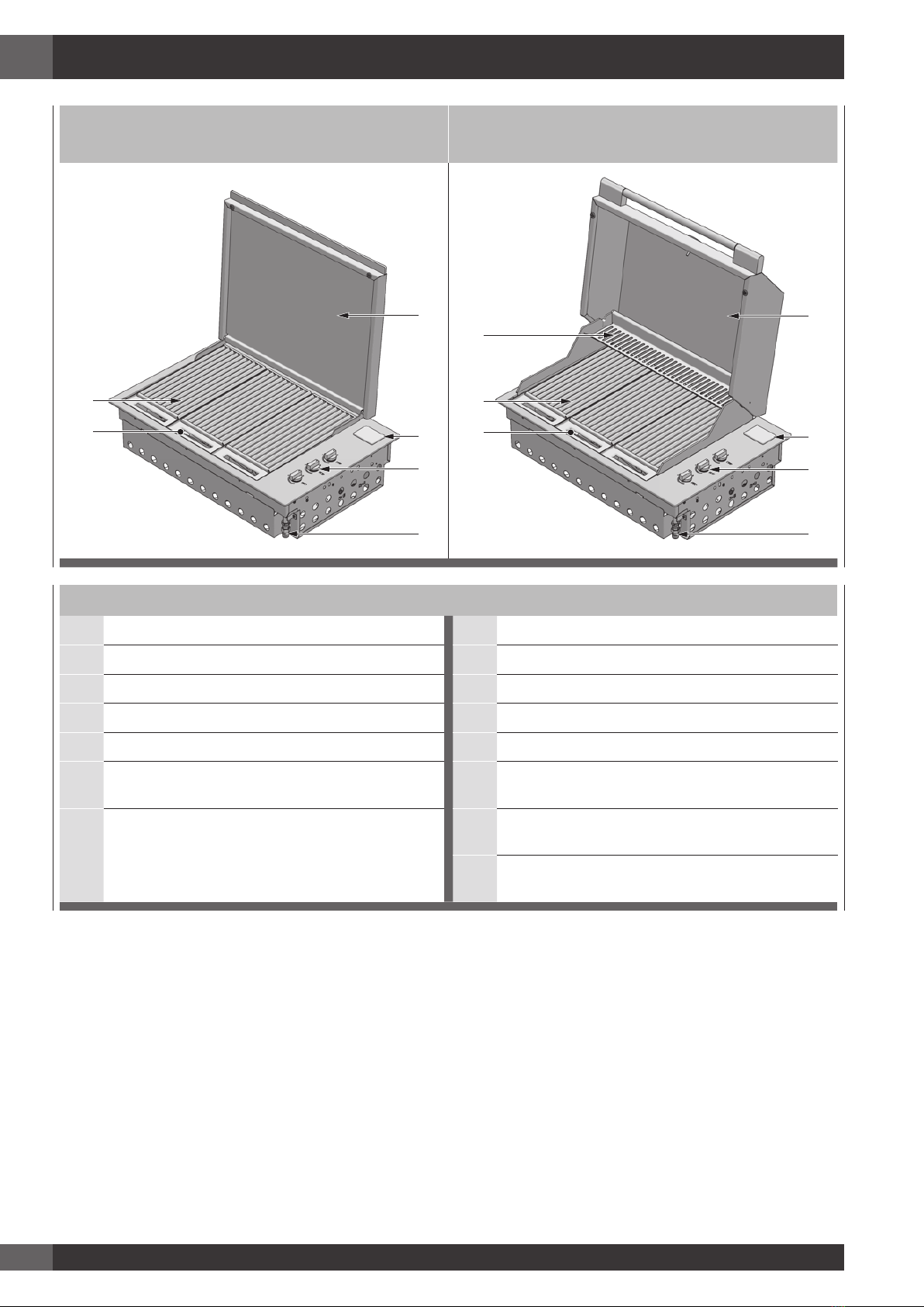
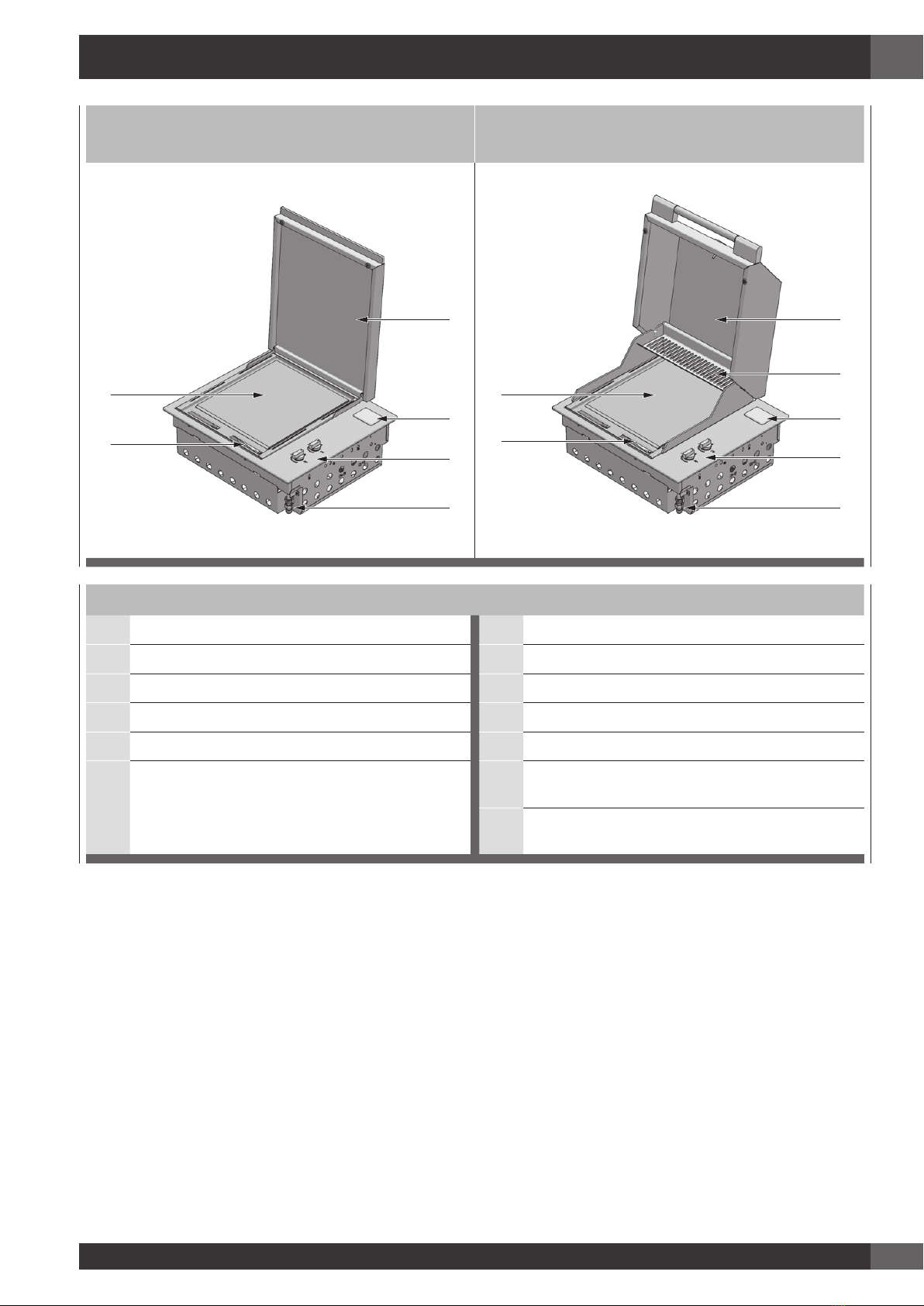
1 - Product description 2
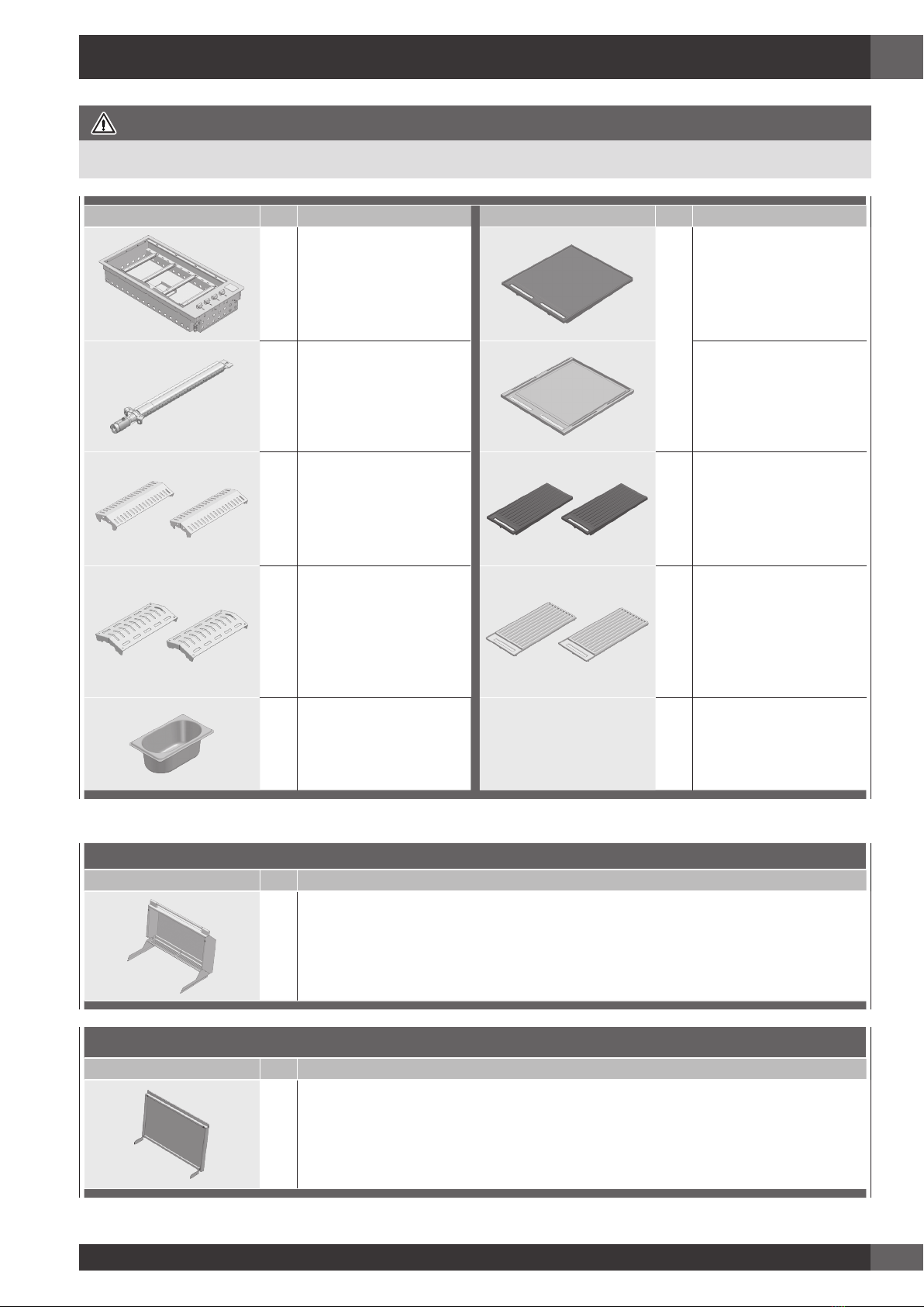
2 - Components 7
3 - Important safety instructions 8
Use 8
The manufacturer’s liability: 10
4 - Assembling the barbecue 11
5 - Characteristics of gas in different countries 13
Adapting to different types of gas 14
Gas connection 15
Rigid and semi-rigid metal and rubber hose
connection 15
6 - Gas cylinder safety information 17
Leak testing procedure 17
7 - Installation instructions and warnings 18
Selection of the point of installation 19
Installation compartment 19
Island-mounted 19
Installation in a counter in a special context 19
8 - Connection of the LPG cylinder 28
TABLE OF CONTENTS PAGE
9 - Application of the cover 29
Application of the low cover 29
Application of the high cover 30
10 - Usage instructions 31
Control functions 34
Ignition instructions 34
Manual lighting 34
Pre-heating cooking areas 34
To turn off the burner 35
11 - Cleaning and care 36
Care and cleaning of the appliance 36
Cleaning of cooking parts 36
Other stainless steel surfaces 36
Cleaning the cooking grills made of cast iron 36
Cleaning the stainless steel grills 36
Cleaning the grease drip pan 37
Burners 37
12 - Maintenance 38
Ignition system 38
Ventilation openings 38
13 - Troubleshooting 39

EN
2
1 - Product description
BARBECUE MOD. FOBQ 1000 G MBK
LOW LID MOD. FOBQ LL 1000 MBK
BARBECUE MOD. FOBQ 1000 G X
LOW LID MOD. FOBQ LL 1000 X
7
1
2
4
3
6
5
7
1
2
4
3
6
5
Integrated barbecue with thin cover
1. Thin cover 1. Thin cover
2. Battery compartment cover 2. Battery compartment cover
3. Gas connection point 3. Gas connection point
4. Burner controls 4. Burner controls
5. Cast iron grills group (2 set) 5. Stainless steel grill group (2 set)
6. Cooking plate 6. Cooking plate
7. Removable oil collection drip plan located in front
of the cooking surface (not shown) 7. Removable oil collection drip plan located in front
of the cooking surface (not shown)
8. Flame diffusers (2 pcs.) located under the grills (not
shown)

EN
3
BARBECUE MOD. FOBQ 1000 G MBK
HIGH LID MOD. FOBQ LL 1000 MBK
BARBECUE MOD. FOBQ 1000 G X
HIGH LID MOD. FOBQ HL 1000 X
8
1
3
5
4
7
6
2
8
1
3
5
4
7
6
2
Integrated barbecue with high cover
1. High cover 1. High cover
2. Heating racks 2. Heating racks
3. Battery compartment cover 3. Battery compartment cover
4. Gas connection point 4. Gas connection point
5. Burner controls 5. Burner controls
6. Cast iron grill group (2 set) 6. Stainless steel grill group (2 set)
7. Cooking plate 7. Cooking plate
8. Removable oil collection drip plan located in front
of the cooking surface (not shown) 8. Removable oil collection drip plan located in front
of the cooking surface (not shown)
9. Flame diffusers (2 pcs.) located under the grills (not
shown)

EN
4
BARBECUE MOD. FOBQ 803 G X
LOW LID MOD. FOBQ LL 800 MBK
BARBECUE MOD. FOBQ 803 G X
HIGH LID MOD. FOBQ HL 800 MBK
6
1
2
4
3
5
7
1
3
5
4
6
2
Integrated barbecue with cover
1. Low cover 1. High cover
2. Battery compartment cover 2. Heating racks
3. Gas connection point 3. Battery compartment cover
4. Burner controls 4. Gas connection point
5. Stainless steel grill group (3 set) 5. Burner controls
6. Removable oil collection drip plan located in front
of the cooking surface (not shown) 6. Stainless steel grill group (3 set)
7. Flame diffusers (3 pcs.) located under the grills (not
shown) 7. Removable oil collection drip plan located in front
of the cooking surface (not shown)
8. Flame diffusers (3 pcs.) located under the grills (not
shown)

EN
5
BARBECUE MOD. FOBQ 601 TY G X
LOW LID MOD. FOBQ LL 600 X
BARBECUE MOD. FOBQ 601 TY G X
HIGH LID MOD. FOBQ HL 600 X
1
2
4
3
5
6
1
3
5
4
6
7
2
Integrated barbecue with cover
1. Low cover 1. High cover
2. Battery compartment cover 2. Heating racks
3. Gas connection point 3. Battery compartment cover
4. Burner controls 4. Gas connection point
5. Cooking plate 5. Burner controls
6. Removable oil collection drip plan located in front
of the cooking surface (not shown) 6. Cooking plate
7. Removable oil collection drip plan located in front
of the cooking surface (not shown)

EN
6
BARBECUE MOD. FOBQ 602 G X
LOW LID MOD. FOBQ LL 600 X
BARBECUE MOD. FOBQ 602 G X
HIGH LID MOD. FOBQ HL 600 X
1
2
4
3
5
6
1
3
5
4
6
7
2
Integrated barbecue with cover
1. Low cover 1. High cover
2. Battery compartment cover 2. Heating racks
3. Gas connection point 3. Battery compartment cover
4. Burner controls 4. Gas connection point
5. Stainless steel grill group (2 set) 5. Burner controls
6. Removable oil collection drip plan located in front
of the cooking surface (not shown) 6. Stainless steel grill group (2 set)
7 Flame diffusers (2 pcs.) located under the grills (not
shown) 7. Removable oil collection drip plan located in front
of the cooking surface (not shown)
8 Flame diffusers (2 pcs.) located under the grills (not
shown)

EN
7
IMPORTANT
The quantity of each component may vary depending on the model.
QTY DESCRIPTION QTY DESCRIPTION
1Burner box and external
profile
1
Large cast iron
cooking plate.
Only for 100cm models.
2 Burners for 60cm model
Stainless steel
cooking plate.
3 Burners for 80cm model
4Burners for 100cm
model
2Flame diffusers for 60cm
model*
2Large cast grill groups
for 100cm model
3Flame diffusers for 80cm
model*
2Flame diffusers for
100cm model*
2Flame diffusers for 60cm
model (optional)* 2Stainless steel grill
groups for 60cm model
3Flame diffusers for 80cm
model (optional)* 3Stainless steel grill
groups for 80cm model
2Flame diffusers
for 100cm model
(optional)* 4Stainless steel grill
groups for 100cm model
1 Oil tray
*Presence depending on the model, see pp. 2-6
CONFIGURATION 1
QTY DESCRIPTION
1 High cover for cooking
CONFIGURATION 2
QTY DESCRIPTION
1 Low cover
2 - Components

EN
8
Use
Carefully read the user manual and keep it in a handy place for future reference.
Below, we explain the meaning of the symbols used in this manual:
ATTENTION
This symbol indicates information relating to the user’s personal safety
WARNING
This symbol indicates information on how to prevent damage to the appliance
TIPS AND INFORMATION
This symbol indicates tips and information about the use of the appliance
SUGGESTION FOR THE ENVIRONMENT
This symbol indicates information for the economical and ecological use of the appliance
PROHIBITION
This symbol indicates a prohibited action
ATTENTION
The appliance MUST only be installed and serviced by qualified and authorized personnel.
Improper installation, modification, adjustment or maintenance can cause personal injury or
property damage.
Contact your nearest Service Centre for further information.
3 - Important safety instructions
For your own safety, you should read this manual before
operating the barbecue.

EN
9
PROHIBITION
• Do not lean over barbecue while lighting.
• Do not leave the barbecue unattended
when it is on.
• Do not delay ignition once the gas is
opened.
• Do not store or use aerosol sprays near the
barbecue.
• Do not store inflammable liquids near the
barbecue.
• Do not use abrasive or caustic detergents
on the barbecue.
• Do not operate the barbecue with the cover
closed.
• Do not attempt to disassemble or adjust the
control valves.
• Do not attempt to disassemble or adjust
the cylinder regulator (not supplied) but, if
necessary, replace with a new one.
• Do not use an open flame to check for leaks.
• Do not modify the structure of the appliance
and do not modify the dimensions of the
injector orifice.
PROHIBITION
• Do not obstruct the ventilation openings of
the barbecue.
• Do not allow children to operate the
barbecue or play near it.
• Do not use the barbecue if inflammable
materials are within a radius of about 60
cm from the top, bottom, rear or sides of
the appliance.
• Keep any electrical wires and fuel hoses
away from hot surfaces.
• Never store a spare gas cylinder near the
barbecue.
• This appliance reaches high temperatures.
Be especially careful when children and
elderly persons are present
• Do not move the barbecue when it is on.
• Wear protective gloves when using the
barbecue.
• Keep children under the age of eight years
away, if not constantly supervised.
• Never attempt to extinguish a flame/fire
with water: turn off the appliance and cover
the flame with a cover or a fire blanket.
NOTE FOR THE INSTALLER: THIS MANUAL MUST BE LEFT WITH THE OWNER FOR FUTURE
REFERENCE
ATTENTION
IF YOU SMELL GAS, do not try to light the barbecue. Perform the leak test procedure described in
this manual. Locate the leak and tighten the leaking fitting; if it is the cylinder fitting, also replace
the gasket seal.
If the leak persists, turn off the gas supply and call for technical assistance.

EN
10
PROHIBITION
• Be careful when handling gas cylinders
even if they appear empty, in compliance
with current safety rules.
• Do not use dented or rusty gas cylinders
• Do not disconnect the gas cylinder from
the appliance when it is on. Perform any
service on the gas cylinder far away from
the appliance.
• Only turn the burners on with the cover lifted
• If the knob becomes difficult to rotate, have
the taps checked by an authorized service
centre.
• Lower the cover, accompanying it with
your hand and make sure that nothing is
obstructing its proper closure.
• When cooking with the cover closed
keep an eye on the thermometer: if the
temperature exceeds 350 °C, lift the cover
to prevent dangerous overheating.
• Do not leave objects on the cooking
surfaces.
• Never use the appliance to heat the area.
• Always close the valve of the gas cylinder
after use.
The manufacturer’s liability:
The manufacturer will not be liable for personal
injury or property damage caused by:
• any use of the appliance other than
anticipated;
• failure to follow the instructions of the user
manual;
• tampering with any part of the appliance;
• use of other than original parts.

EN
11
4 - Assembling the barbecue
Tools needed for assembly:
- Phillips screwdriver
1. Remove all components from the box.
BACK
FRONT
2. Place the flame diffusers in the desired positions (under
the points (A) in which the grill sections will be placed)
and attach the rear edge of the flame diffuser to the rear
of the body of the barbecue.
BACK
FRONT
3. Apply the oil drip pans to the front of the barbecue.
BACK
FRONT
BACK
FRONT
4. Place the cooking plate and grill sections in the desired
positions, making sure that the flame diffusers are under
the grill sections.
NOTE: Make sure that the grill groups are correctly oriented
so that the surface of the grill is tilted forward to
allow the oil to drain into the drip pans.
CAST IRON GRILLS GROUPS

EN
12
STAINLESS STEEL GRILLS GROUPS
FRONT
BACK
5. After installation in the counter, connect the thin cover
or cooking hood area as described in the chapter
“Application of the thin cover or cooking hood” in this
manual.

EN
13
CATEGORY GAS AND PRESSURES
COUNTRIES OF DESTINATION
AT BE CY HR DK EE FI FR DE GR IE IS IT LV LT LU MT NO NL PT PL GB CZ RO SK SI ES SE CH TR HU
I3+ G30 /G31 = 28-30/37 mbar • • • • • • • • • • • • • • •
I3B/P(30) G30 /G31 = 30 mbar • • • • • • • • • • • • • • • • • • •
I3B/P(37) G30 /G31 = 37 mbar •
I3B/P(50) G30 /G31 = 50 mbar • • • • •
2H G20 = 20 mbar • • • • • • • • • • • • • • • • • • • • • •
2E G20 = 20 mbar • • • • •
2E+ G20 = 20 mbar • •
2L G25 = 25 mbar •
2LL G25 /20 mbar • •
2H(25) G20 /25 mbar •
2S G25.3 /25 mbar • •
2Lw G27 /20 mbar •
2Ls G2.350/13 mbar •
G20-20
cat. 2H, 2E, 2E+
G20-25
cat. 2H(25)
G25-20
at. 2LL
G25-25
cat.2L
G25.3
cat.2S
G27
cat.2Lw
G2.350
cat.2Ls
G30 /G31
cat. I3+
G30 /G31
cat. I3B/P (30)
G30 /G31
cat. I3B/P (37)
G30 /G31
cat. I3B/P (50)
Nominal heat input (kW) 15,2 15,2 15,2 15,2 15,2 15,2 15,2 15,2 15,2 15,2 15,2
Injector diameter (1/100mm) 135 130 155 145 145 155 194 94 94 89 83
Number of injectors 4 4 4 4 4 4 4 4 4 4 4
Pressure (mbar) 20 25 20 25 25 20 13 28..30/30..37 30 37 50
Maximum consumption (l/h) 1448 1448 1684 1684 1683 1766 2011 1106 1106 1106 1106
Primary air regulation (mm)
(X) see fig. page 15 1 1 1 1 1 1 1 All open All open All open All open
5 - Characteristics of gas in different countries

EN
14
Adapting to different types of gas
If the appliance is configured for a different type of gas than
that available, you have to replace the injectors with ones
corresponding to the type of gas to be used (see tables on
the preceding pages). The replacement will be made using
an adequate 7 mm key after having lowered the burners as
in the following images. After replacing the injector, regulate
the air to 1mm for natural gas and to the maximum if LPG.
To adjust the minimum, after lighting the burner, remove the
knob and the gasket below and rotate the screw of the tap
(B - see page 15), which should be totally closed for
LPG and opened about 3/4 turn for natural gas, keeping
in mind that a flame lower than 3 mm may not even be
“perceived” by the thermocouple of the tap. After regulating
the minimums, replace the gaskets and knobs.
1 - Unscrew the fixing screws of the burner.
BACK
FRONT
2 - Lower the burner and replace the injector.
FRONT
BACK

EN
15
X
NOTES
• The appliance MUST only be installed and serviced by
qualified and authorized personnel.
• The product is exclusively intended for outdoor use.
• The product must be installed according to the instructions,
which require ventilation openings to allow the grill to work
properly. The lack of adequate ventilation to supply air to
the appliance can lead to poor operation of the burners or
excessive heat build-up in the installation compartment.
• The unit’s ventilation openings must not be covered during
installation.
Gas connection
Connect the appliance to the cylinder or system according to
the requirements of current law, making sure that the appliance
is configured for the type of gas available. If not, see: “Adapting
to different types of gas”. Also check that the feed pressure falls
within the values shown in the table: “Gas specifications”.
Rigid and semi-rigid metal and rubber hose
connection
Make the hook-up with metal fittings and pipes (even flexible
hoses) so as not to stress the components inside the appliance.
A rubber hose connection complies with current law only if
the hose can be inspected along its entire length and easily
replaced near the expiration indicated on the hose.
NOTE: - After installation, use soapy water to check the perfect
seal of the entire connection system. DO NOT USE AN OPEN
FLAME TO CHECK THE GAS SEAL.

EN
16
Detail of the gas connection
52 47488
With note: natural gas connection NG.

EN
17
6 - Gas cylinder safety information
• When converted for the use of universal
LPG, the appliance is designed to use
different types of cylinders depending on
the installation made. See the chapters on
Installation Preparation and Connection of
the cylinder.
• The gas cylinder must be manufactured and
marked in accordance with the specifications
for LPG cylinders.
• The shut-off valve must be closed when the
appliance is not in use.
• The gas cylinders must be kept in an approved
housing out of the reach of children.
• When you disconnect the gas cylinder, make
sure all the control valves are in the “OFF”
(O) position.
• Before disconnecting, remove the cylinder
from any housing in which it may be located.
• When you reconnect the hose to the cylinder,
make sure all the connections are tight before
placing it back in its compartment.
• After each connection of a cylinder, perform
a leak test as described below.
Leak testing procedure
• Make sure that all the gas taps are in the
“OFF” (O) position.
• Mix a solution of water and detergent or
soap in a small container.
• After connecting the hose, open the valve on
the gas cylinder or gas system tap.
• Using a brush, paint the solution on the gas
connection points and check for bubbles.
• Bubbles indicate a leak.
• Close the valve and tighten the fitting, possibly
inserting a new gasket. Repeat the leak test.
• If the leak persists, turn off the gas and contact
an authorized gas system maintenance
technician to repair the leak.

EN
18
7 - Installation instructions and warnings
ATTENTION
• The appliance must only be used above ground level,
in open air and natural ventilation without stagnant
areas where leaking gas and combustion products are
rapidly dispersed by the wind or natural convection.
This barbecue is designed exclusively for outdoor use.
Refer to the drawings below.
• Never install the barbecue inside buildings, garages,
sheds or covered walkways, or in a boat, camper or
caravan. This prevents the creation of fires or carbon
monoxide with toxic effects or asphyxiation.
• The compartment in which the appliance is installed
must conform to one of the following requirements:
ATTENTION
• A compartment with walls on all sides, but with at least
one permanent opening at ground level and without
upper cover.
• In a partial compartment that has a top cover and not
more than two walls.
• In a partial compartment that has a top cover and
not more than two walls; in this case, the following
principle applies:
• At least 25% of the total area of the walls is completely
open and at least 30% of the remaining area of the
walls is open and free.
• In the case of balconies, at least 20% of the total area
of the side, front and rear walls must be and remain
open and free.
External surface area example 1
External surface area example 2
External surface area example 3
both ends open
External surface area example 4
open side for at least 25% of the total area of the walls in total 30% or more of the
remaining surface of the walls is open and free
External surface area example 5
open side for at least 25% of the total area of the walls in total 30% or more of the
remaining surface of the walls is open and free
Other manuals for FOBQ 1000 G X
1
This manual suits for next models
4
Table of contents
Other Fulgor Milano Grill manuals
Popular Grill manuals by other brands

GardenGrill
GardenGrill Premium 2.1 Original instruction manual

Onward
Onward Broil King REGAL 500 owner's manual

KitchenAid
KitchenAid KFRS271TSS Technical education

Dyna-Glo
Dyna-Glo DGJ810CSB-D user manual

Hamilton Beach
Hamilton Beach HealthSmart 25219 instruction manual

Magma
Magma Delmar DM10-016NG owner's manual

Clas Ohlson
Clas Ohlson 31-6429 instruction manual

Big Green Egg
Big Green Egg EGG Nest L Assembly instructions

Bestron
Bestron ARC650 instruction manual

Great Outdoors
Great Outdoors A053041 Assembly & owners manual

Westinghouse
Westinghouse WST3005ZE owner's manual

Nexgrill
Nexgrill G4NEXDX operating instructions