EN
6
3.1 Transport to installation site and unpacking
WARNING
The appliance is very heavy.
Take maximum care during handling to avoid injury.
IMPORTANT
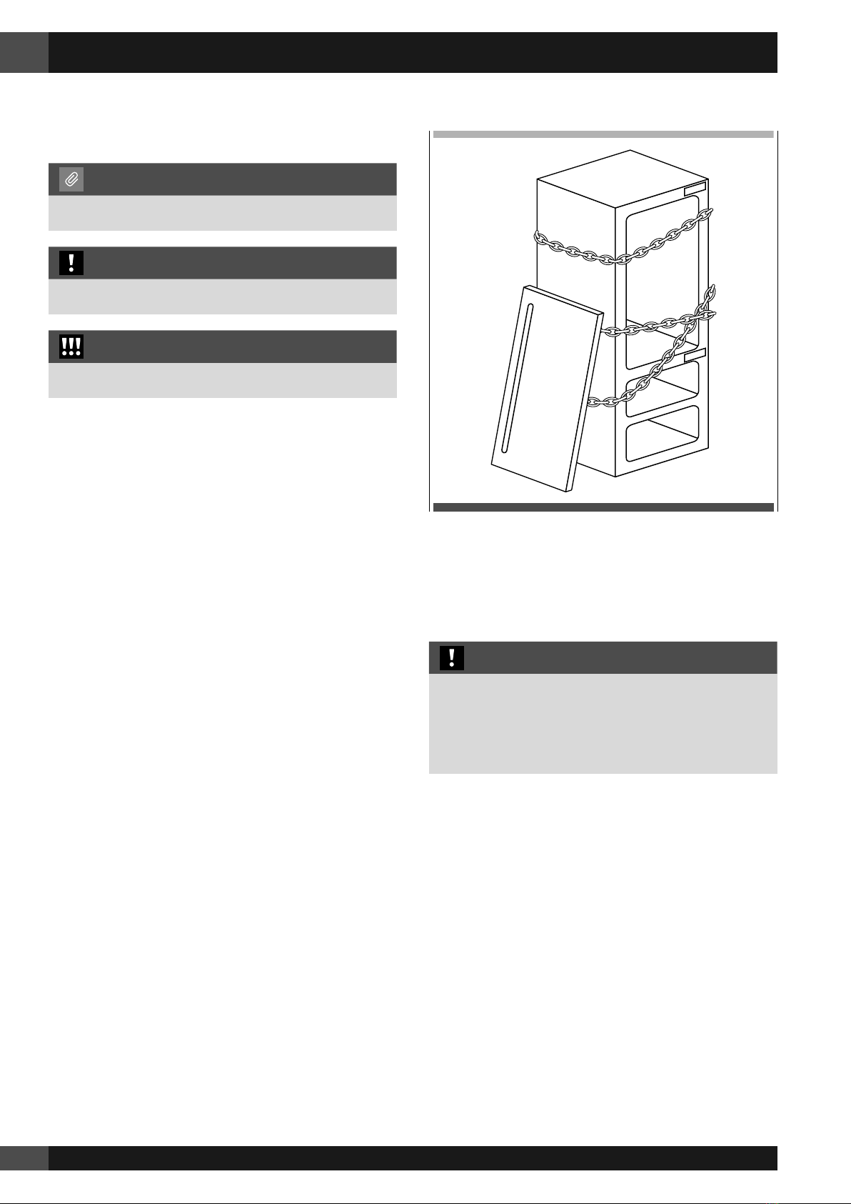
The appliance should always be transported in an erect
position.
Avoid at all costs leaning it on its front side.
1
4
1
2
3
Since this is a large and heavy appliance, before
transporting the appliance, check the access to the location
where it will be installed (door size, manoeuvring space in
stairwells, etc.).
The appliance is attached to the base of the packaging
(pallet) through four bolts which can be removed using a 19
mm (3/4”) wrench.
It is recommended to use a manual transporting device to
move the appliance to the installation site, and only at this
point to remove the base of the packaging.
The appliance should always be transported in an erect
position.
If this is not possible, transport the appliance laying on its
rear side.
Once at the installation site, the appliance, which is
equipped with four wheels, can be taken off the pallet and
positioned in the installation area.
Operate as follows:
• Take off the four bolts securing [ 1 ] the appliance to the
pallet by means of a 19 mm (3/4”) wrench or socket.
• Remove the fixing brackets [ 3 ] and [ 4 ].
• To release the front fixing bracket [ 3 ], unscrew the rear
wheel adjusting bolt [ 2 ] by means of a 13 mm (1/2”)
wrench or socket. Avoid straining this bolt at its stop
points one way or the other so as to not damage the rear
leveling system.
Ensure the front leveling legs are retracted so that
all 4 wheels are able to contact the floor for easiest
maneuvering.
• From the back of the unit and by means of a suitable,
high duty hand trolley, take off the appliance and place
it on the floor.
Be very careful to avoid any damage to floors. Delicate
floors should be protected with plywood, hard cardboard
or similar material panels.
3.2 Electrical and Water connection
NOTE
The Built-in filter cannot make it safe to drink any water
which is not already suitable for human consumption.
WARNING
The appliance should be connected only to a potable
water supply system.
IMPORTANT
Do not use extension cords or adapters.
Once the appliance is fully installed, connected to the
water supply (if applicable) and operational, in the event
that the water supply must be turned off, touch the button
on control panel to disable the ice maker before the
main water is shut off to prevent the appliance from
entering a ‘NO WATER IN’ alarm state.
EW
E W
EW
E W
The appliances are delivered from the factory for operation
at 110V-120V AC - 60Hz (US and Canada).
They are provided with a suitable supply cable and plug to
be connected to an appropriate 15A socket providing an
effective grounding.
A dedicated 15A circuit breaker should also be installed and
should be easily accessible so that it can be easily switched
off before performing any installation or maintenance.
3. Preparing The Installation