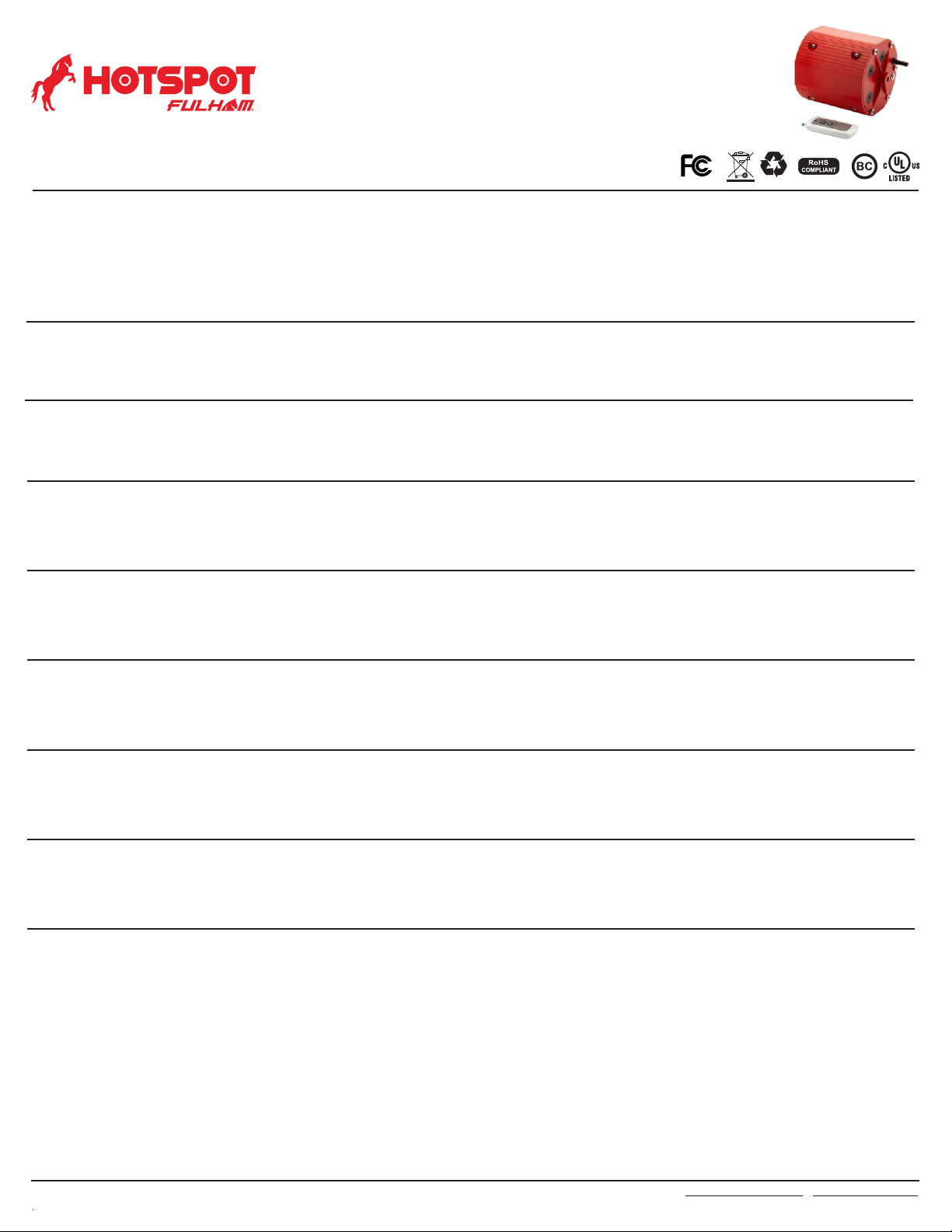
FHSHB-347-40W-D Lithium
2023-959 Rev A
> Open the cover of junction box.
> Before wiring, make sure safety rope is securely locked and make sure all the screws are tight.
> The Maximum weight of lighting fixture should be less than 20kg.
> Select a suitable location on the hangable device.
WHEN USING ELECTRICAL EQUIPMENT, BASIC SAFETY PRECAUTION
SHOULD ALWAYS BE FOLLOWED, INCLUDING THE FOLLOWING
1. CAUTION- This FHSHB provides more than one power supply output source. To reduce the risk of electrical shock, disconnect both normal and
emergency source by turning o the A.C. branch circuit.
2. CAUTION- Servicing of this equipment should be performed by qualified personnel only.
3. CAUTION- Do not attempt to service the battery. A sealed, no-maitenence battery is used that is not field replaceable. Replace the entire unit when necessary.
4. CAUTION- The use of accessory equipment not recommended by the manufacturer may cause an unsafe condition, void warranty, and result in
non-compliance with UL specifications.
5. CAUTION- The FHSHB requires an un-switched AC power source of 100-347VAC ,50/60Hz. Installer must confirm that fixtures input voltage.
covered 120VAC before installation. It will supply power under an output voltage of 170VDC in emergency mode for at least 90 minutes.
6. CAUTION- Battery pack should be charged for 24 hours every 6 months during storage.
7. Battery in this unit may not be fully charged. After electricity is connected to the unit for at least 24 hours, then normal operation of this unit should take effect.
8. For use in 0℃ minimum, 50℃ maximum ambient temperatures. Suitable for use in wet locations and plenum spaces.
9. Flexible mental conduit is optional, depend on installation environment.
10. The FHSHB should be mounted in locations and at heights where it will not readily be subjected to tampering by unauthorized personnel.
11. Do not use this equipment for anything other than its intended use. Equipment only use for LED Lighting emergency backup.
12. Do not mount near gas or electric heaters. Do not let power supply cords touch hot surfaces.
13. Do not make or leave any other open holes in the wiring enclosure or electrical component enclosure during installation.
14. This fixture is for use with grounded, UL Listed, this model can use in wet location. Not for use in heated air outlets or hazardous locations.
18. Suitable for minimum 10W LED lamp.
16. Equipment should be mounted in locations and at heights where it will not be subjected to tampering by unauthorized personnel.
17. The equipment is intended for ordinary locations and for permanent installation into one or more Listed emergency luminaires.
INSTALLATION MANUAL
15. The emergency driver have battery inside,forbidden for insulation voltage(I/P-O/P) test.
FHSHB347-40W-D’is 40 W 100 LM/W = 4000 Lumens
!!! IMPORTANT SAFEGUARDS !!!
> The battery in this unit may not be fully charged. A short-term discharge test may be conducted after the EMUFO has been charging for 1 hour.
Charge for 24 hours before conducting a long-term discharge test.
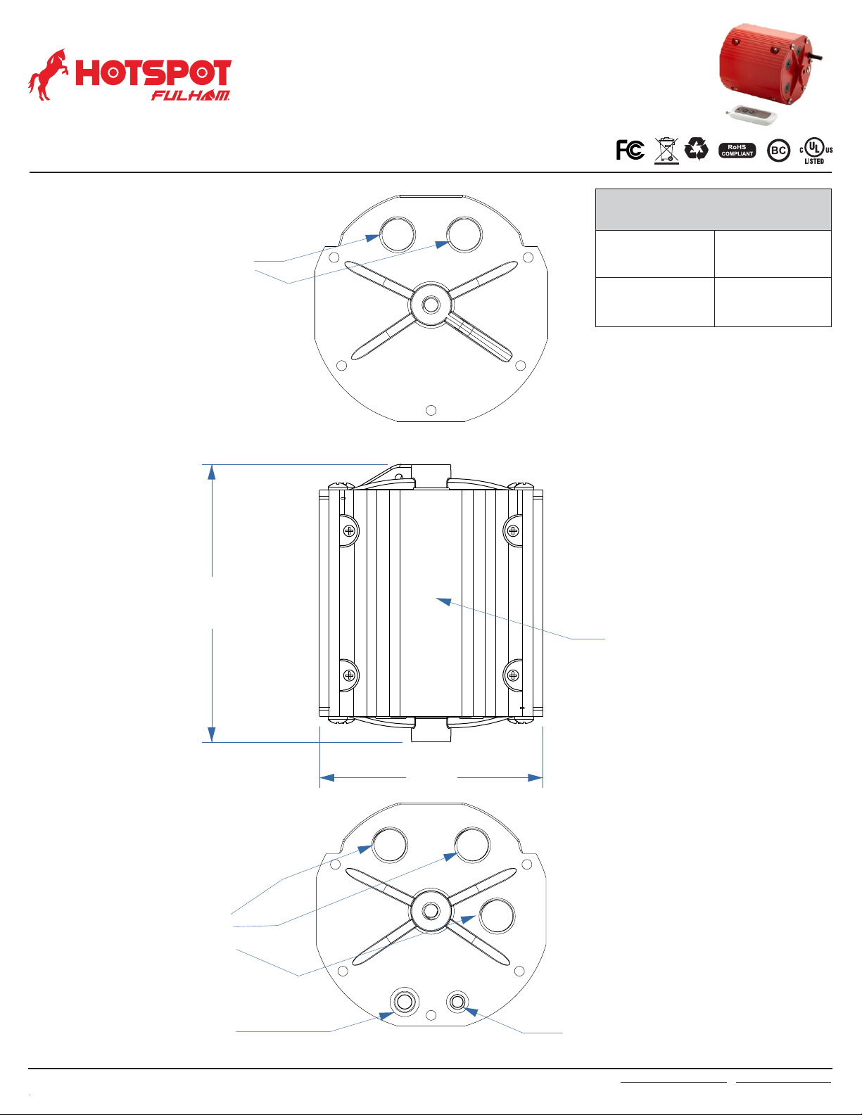
STEP 1: ASSEMBLING NOTICE
STEP 2: INSTALLING
> Turn off the AC power before installing.
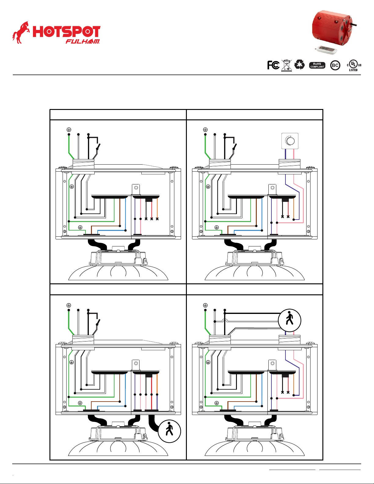
STEP 3: WIRING
> Select the appropriate wiring diagram to connect the emergency driver to the AC driver. For other diagrams, consult the manufacturer.
STEP 4: TESTING
> Using wire nuts to cover un-used wires and make sure all connections are in accordance with the NEC and any local regulations.
> Assembling the EM backup with the Safety Rope with the chain link connector.
> The voltage input to the dimmable wires (DIM+, DIM-) of emergency LED driver must less than 20Vdc.
> After wiring is complete, apply A.C. power. Check if the indicator light lights or not , which will indicate the battery’s charging situation.
> Please use waterproof connectors in position AC input wire interface and Dimming wire interface for application in wet location.
> Install the ring M10 Hanging Ring Bolt to the EM backup and fix it with screw.
> Install the M10 Hanging Hook Bolt to the EM backup and fix it with screw.
> Install the UFO high bay to the Hanging Hook of EM backup and tighten the screws.
This product has been designed and tested to compatible with most of led drivers in the market. However, compatibility cannotbe guaranteed
with all current and future LED drivers or fixtures. So compatibility testing of the end-use system is suggested.
Please contact the factory with any questions.
19. Maximum installation height: 28.5 feet.
READ AND FOLLOW ALL SAFETY INSTRUCTION
Fulham Co. Inc.: 12705 South Van Ness Ave., Hawthorne, CA 90250 Tel.: 1-323-779-2980 Fax.: 1-323-754-9060.
Specifications subject to change without notice.
Page 7 of 9
E477042