Fulham Firehorse FH10-DUAL-500L User manual

MECHANICAL DATA
ELECTRICAL DATA
Project_______________________Type______________Model #___________
Remarks__________________________________________________________
T8
T5
This Ballast Will Operate Following Lamps.
1 X F21T5, F28T5, F32T8, F40T12 (34W), 32WCRT9, 22W CRT5, FB32T8, FB34T12
BALLAST TYPE / OUTPUT TYPE
EMERGENCY
INPUT VOLTAGE
120V OR 277V 10%, 60 Hz+
AC INPUT POWER RATING
2.7W
AC INPUT CURRENT RATING
130mA
BATTERY TYPE
MAINTENANCE FREE - HIGH TEMPERATURE RECHARGEABLE SEALED NI-CAD
BATTERY VOLTAGE
3.6Vdc
BATTERY CHARGING CURRENT
110mA
BATTERY RATING
9.0Wh
BATTERY CAPACITY
2.5Ah
TEMPERATURE RATING (AMBIENT)
0°C TO 50°C (32°F TO 122°F)
MAX INITIAL LIGHT OUTPUT
500 LUMENS
MINIMUM ILLUMINATION TIME
90 MINUTES
RECHARGE TIME
24 HOURS
TEST SWITCH TYPE
ILLUMINATED TEST SWITCH PILOT LIGHT
CHARGING INDICATOR LIGHT TYPE
LED
CASE PROFILE
14.17”L X 1.22”W X 1.14”H X 13.67” MOUNTING CENTER
CASE WEIGHT
1.8 lbs.
CASE TYPE
VANDAL RESISTANT - SEALED
CASE CONTRUCTION
GALVANIZED STEEL
WIRE CONNECTION
STANDARD WIRE LEADS
APPROVAL CLASS
UL - LISTED FOR DAMP LOCATION - FACTORY OR FIELD INSTALLATION
CODE COMPLIANCE
MEETS OR EXCEEDS UL924 - N.E.C AND NFPA 101 LIFE SAFETY CODE EMERGENCY OPERATING REQUIREMENT
AC COMPATIBILITY
ELECTRONIC FLUORESCENT - STANDARD AND DIMMING
LAMP COMPATIBILITY
FLUORESCENT SINGLE / BI-PIN / 4-PIN WITHOUT INTEGRAL STARTER
LUMINAIRE COMPATIBILITY
INDOOR SWITCHED AND UN-SWITCHED
END OF LIFE (EOL) COMPATIBILITY
YES (TIME DELAY CIRCUIT)
WARRANTY
5 YEARS
Input
Output
Wire Color
Wire Length
Wire Color
Wire Length
Black
45.0”
Blue
45.0”
Black/White
37.0”
Blue/White
45.0”
White
45.0”
Yellow
45.0”
Orange
45.0”
Red
45.0”
Connector
Red/White
45.0”
White
28.0”
Violet
45.0”
White
28.0”
Brown
45.0”
Ni-Cd
DAMP
WIRE LENGTH (Inches)
SPECIFICATION SHEET: FH10-DUAL-500L
TOP VIEW
SIDE VIEW
1/17
Fulham Co. Inc. Address : 12705 South Van Ness Ave., Hawthorne, CA 90250 Tel.: 1-323-779-2980, Fax.: 1-323-754-9060. Website: www.fulham.com
Description: Firehorse Emergency Ballast for use with or without AC ballast designed to add emergency lighting when main AC power
is interrupted for minimum of 90 minutes at reduced illumination. The emergency ballast is not intended for general purpose lighting applications.
Complies with minimum light output for emergency lighting equipment as per UL 924, supplement “SH”. Consult with factory when using EM
Ballast with low mercury lamps (TCP).
2006-132-1 Rev J

APPLICATION
The FireHorse emergency ballast can be used to add emergency lighting with or without an
AC ballast and with most fluorescent luminaires without affecting normal luminaire operation.
The emergency ballast is designed for factory or field installation and can be mounted on top,
inside, or remote from the luminaire.
If used in an emergency-only luminaire, no AC ballast is required. The FireHorse emergency
ballast is not suitable for use in air handling heated air outlets, outdoor, wet, or hazardous
locations. The emergency ballast should not be installed near gas or electric heaters. The
FireHorse emergency ballast is rated for Indoor Dry/Damp locations, including luminaires
rated for UL wet locations .
OPERATION
The FireHorse emergency ballast is designed to immediately switch to the emergency mode
when the primary AC power is interrupted, illuminating one or two lamps at a reduced lumen
output for a minimum of 90 minutes. Upon restoration of primary AC power; the FireHorse
emergency ballast immediately returns to a battery charging mode. The LED indicator light
source when illuminated indicates battery is in charge mode when AC power is applied.
It is recommended and by code required to test the emergency ballast every 30 days to
ensure that the ballast is functioning as evidenced by reduced illumination of one or two
lamps when pushing the test switch. It is also recommended a 90 minute discharge test is
performed one time every 12 months. Battery requires 24 hours to fully re-charge.
INSTALLATION
The FireHorse emergency ballast may be used with either a switched or un-switched
luminaire. If a switched luminaire is used, an un-switched hot lead must be connected to
the emergency ballast to ensure the ballast remains in an uninterrupted charge condition
while primary AC power source is active. Reference Installation Instructions for appropriate
wiring or contact Fulham Customer Service.
The FireHorse emergency ballast must be fed from the same branch circuit as the AC
ballast. Installation is not recommended with luminaires where the ambient temperature
may fall below 0° C for extended periods as this may
affect the operation of the emergency ballast.
REMOTE MOUNTING
The FireHorse emergency ballast may be remote-installed up to half the distance the AC
ballast manufacturer recommends for remote mounting the AC ballast from the lamp, or up
to 50 feet, whichever is less distance. The remote test switch plate may be mounted
within 50 feet of the luminaire and is subject to NEC and applicable local electrical code.
UL and CODE COMPLIANCE
The FireHorse emergency ballast has been tested by Underwriters Laboratories in
accordance with the standards contained in UL924, “Emergency Lighting and Power
Equipment”, and is UL approved for factory or field installations. Emergency illumination
time meets or exceeds the National Electrical Code (NEC), Life Safety Code (NFPA-LSC)
and UL 90 minute requirements. This product does not meet CEC Title 20 Code of
Regulations.
BATTERY
The FireHorse emergency ballast contains a uniquely constructed, high-temperature
rechargeable nickel cadmium battery. The battery is sealed within the ballast housing and
is not replaceable. The battery must be recycled or disposed of properly and in compliance
with federal, state and local regulations.
EMERGENCY ILLUMINATION
Illumination output varies with number of lamps, either 1 or 2 lamps, and lamp wattage
requirement. The FireHorse model FH10-DUAL-500L is designed to produce 320-500
initial emergency lumens output; if model works with 2 lamps the total initial lumens is
distributed between the 2 illuminated lamps. Refer to Table 1 for average lumen output
for selected lamps.
SPECIFICATION
Emergency lighting shall be provided by using a FireHorse emergency ballast with a
standard fluorescent luminaire equipped with or without an AC ballast. The emergency
ballast shall be capable of operating one or two fluorescent lamps as referenced in Table 1.
The emergency ballast shall conform to specifications contained in Electrical Data Table
and comply with standards set forth by the current NEC. The emergency ballast shall be
UL approved for installation on top, inside, or remote from the luminaire.
NOTE: USE OF LOW MERCURY "GREEN" LAMPS
A growing number of fluorescent lamp manufacturers have reduced the level of mercury
content in their products. While this is helpful to the environment, the lower mercury content
makes the lamp more difficult to start in emergency mode, particularly in a compact
fluorescent cold-start emergency-only application without an AC ballast. Please contact
Fulham Customer Service for further assistance if needed.
WARRANTY
Fulham Co., Inc. extends limited warranty only to the original purchaser or to the first
user for the period of from the date of manufacture as indicated by the date5 years
code stamped on each product and when properly installed and under normal conditions
of use. For additional warranty guide line, please refer to our Complete Product Catalog
(www.fulham.com) OR call Customer Service at 1-323-779-2980. Due to a program of
continuous improvement, Fulham Co., Inc. reserves the right to make any variation in design
or construction to the equipment described.
Full compatible lamp list - lumen ratings may vary with lamp specifications,
light loss, lamp and luminaire maintenance and other utilization factors.
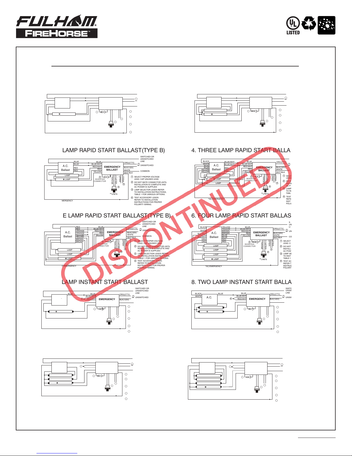
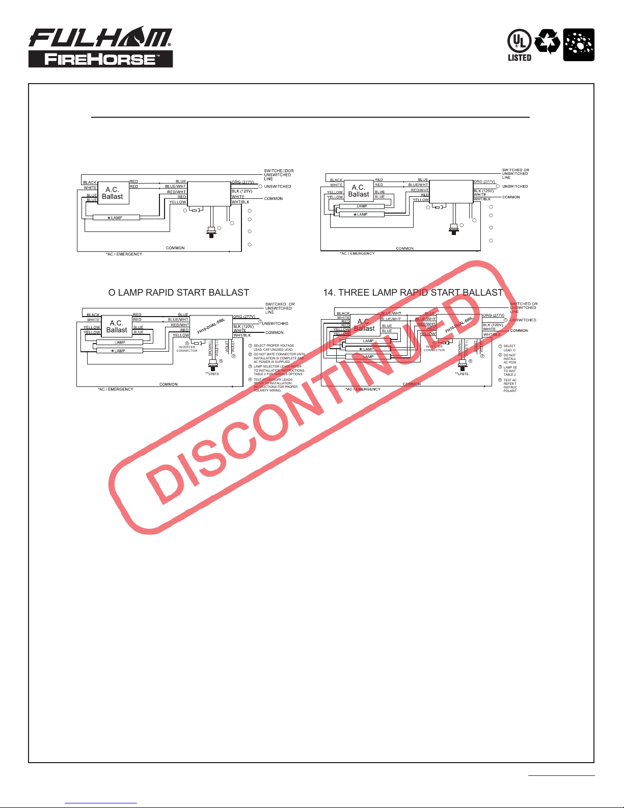
NOTE: WIRING DIAGRAMS SHOWN ON SEPARATE SHEET
F21T5
21W
450
OPEN
X
X
F28T5
28W
500
OPEN
X
X
F32T8
32W
425
OPEN
X
X
F34T12
39W
400
OPEN
X
X
CRT9
32W
320
CLOSED
X
X
CRT5
22W
375
CLOSED
X
X
FB32T8
32W
425
OPEN
X
X
FB34T12
34W
375
OPEN
X
X
TABLE 1
LUMEN OUTPUT CHART
Ni-Cd
DAMP
SPECIFICATION SHEET: FH10-DUAL-500L
Hardware kit and instruction
sheets are included with
EM Ballast.
WATTS
FH10-DUAL-500L
WITHOUT
INTEGRAL
STARTER
2-LAMPS
INITIAL
LUMEN
OUTPUT
1 LAMP
INITIAL
LUMEN
OUTPUT
VIOLET
LEADS
VIOLET
LEADS
1 LAMP
2-LAMPS
Fulham Co. Inc. Address : 12705 South Van Ness Ave., Hawthorne, CA 90250 Tel.: 1-323-779-2980, Fax.: 1-323-754-9060. Website: www.fulham.com
“X” INDICATES LAMP COMBINATION NOT COMPATIBLE
1/17
2006-132-2 Rev J

2006-132-3 Rev J
Ni-Cd
DAMP
WIRING DIAGRAMS FOR ONE LAMP EMERGENCY OPERATION
TYPICAL SCHEMATICS ONLY. MAY BE USED WITH OTHER BALLASTS. CONSULT THE FACTORY FOR OTHER WIRING DIAGRAMS.
EMERGENCY BALLAST AND AC BALLAST MUST BE FED FROM THE SAME BRANCH CIRCUIT
SPECIFICATION SHEET: FH10-DUAL-500L
Fulham Co. Inc. Address : 12705 South Van Ness Ave., Hawthorne, CA 90250 Tel.: 1-323-779-2980, Fax.: 1-323-754-9060. Website: www.fulham.com
1. ONE LAMP RAPID START BALLAST
BLACK
WHITE
RED
RED
BLUE
BLUE
BLUE
BLUE/WHT
RED/WHT
RED
YELLOW
LAMP
*AC/EMERGENCY
SWITCHED OR
UNSWITCHED
LINE
UNSWITCHED
COMMON
SELECT PROPER VOLTAGE
LEAD. CAP UNUSED LEAD.
ORG(277V)
BLK(120V)
WHITE
WHT/BLK
DO NOT MATE CONNECTOR UNTIL
INSTALLATION IS COMPLETE AND
AC POWER IS SUPPLIED
LAMP SELECTOR LEADS-REFER
TO INSTALLATION INSTRUCTIONS,
TABLE 1 FOR VARIOUS OPTIONS.
VIOLET
VIOLET
TEST ACCESSORY LEADS-
REFER TO INSTALLATION
INSTRUCTIONS FOR PROPER
POLARITY WIRING.
1
3
1
2
3
4
EMERGENCY
BALLAST
A.C.
Ballast
6. FOUR LAMP RAPID START BALLAST
BLACK
WHITE
BLU/WHT
YELLOW BLUE
BLUE/WHT
RED/WHT
RED
YELLOW
LAMP
*AC/EMERGENCY
SWITCHED OR
UNSWITCHED
LINE
UNSWITCHED
COMMON
SELECT PROPER VOLTAGE
LEAD. CAP UNUSED LEAD.
ORG(277V)
BLK(120V)
WHITE
WHT/BLK
DO NOT MATE CONNECTOR UNTIL
INSTALLATION IS COMPLETE AND
AC POWER IS SUPPLIED
VIOLET
VIOLET
TEST ACCESSORY LEADS-
REFER TO INSTALLATION
INSTRUCTIONS FOR PROPER
POLARITY WIRING.
1
3
1
2
3
4
A.C.
Ballast
LAMP
RED
RED
BLU/WHT
ORG
ORG
LAMP
LAMP
YELLOW
BROWN
BROWN
BLUE
BLUE
LAMP SELECTION LEADS-REFER
TO INSTALLATION INSTRUCTIONS,
TABLE 1 FOR VARIOUS OPTIONS.
EMERGENCY
BALLAST
2. TWO LAMP RAPID START BALLAST(TYPE A)
BLACK
WHITE
YELLOW
BLUE
BLUE
BLUE
BLUE/WHT
RED/WHT
RED
YELLOW
LAMP
*AC/EMERGENCY
SWITCHED OR
UNSWITCHED
LINE
UNSWITCHED
COMMON
SELECT PROPER VOLTAGE
LEAD. CAP UNUSED LEAD.
ORG(277V)
BLK(120V)
WHITE
WHT/BLK
DO NOT MATE CONNECTOR UNTIL
INSTALLATION IS COMPLETE AND
AC POWER IS SUPPLIED
VIOLET
VIOLET
TEST ACCESSORY LEADS-
REFER TO INSTALLATION
INSTRUCTIONS FOR PROPER
POLARITY WIRING.
1
3
1
2
3
4
A.C.
Ballast
YELLOW
LAMP
RED
RED
LAMP SELECTOR LEADS-REFER
TO INSTALLATION INSTRUCTIONS,
TABLE 1 FOR VARIOUS OPTIONS.
EMERGENCY
BALLAST
7. ONE LAMP INSTANT START BALLAST
BLACK
WHITE
BLUE
BLUE/WHT
RED/WHT
RED
YELLOW
LAMP
*AC/EMERGENCY
SWITCHED OR
UNSWITCHED
LINE
UNSWITCHED
COMMON
SELECT PROPER VOLTAGE
LEAD. CAP UNUSED LEAD.
ORG(277V)
BLK(120V)
WHITE
WHT/BLK
DO NOT MATE CONNECTOR UNTIL
INSTALLATION IS COMPLETE AND
AC POWER IS SUPPLIED
VIOLET
VIOLET
CONNECT BLU/WHT AND RED/WHT
WIRES TOGETHER
1
3
1
2
3
4
A.C.
Ballast
RED
BLUE
4
TEST ACCESSORY LEADS-
REFER TO INSTALLATION
INSTRUCTIONS FOR PROPER
POLARITY WIRING.
5
LAMP SELECTOR LEADS-REFER
TO INSTALLATION INSTRUCTIONS,
TABLE 1 FOR VARIOUS OPTIONS.
EMERGENCY
BALLAST
3. TWO LAMP RAPID START BALLAST(TYPE B)
BLACK
WHITE
YELLOW
BLUE
BLUE
BLUE
BLUE/WHT
RED/WHT
RED
YELLOW
LAMP
*AC/EMERGENCY
SWITCHED OR
UNSWITCHED
LINE
UNSWITCHED
COMMON
SELECT PROPER VOLTAGE
LEAD. CAP UNUSED LEAD.
ORG(277V)
BLK(120V)
WHITE
WHT/BLK
DO NOT MATE CONNECTOR UNTIL
INSTALLATION IS COMPLETE AND
AC POWER IS SUPPLIED
VIOLET
VIOLET
TEST ACCESSORY LEADS-
REFER TO INSTALLATION
INSTRUCTIONS FOR PROPER
POLARITY WIRING.
1
3
1
2
3
4
A.C.
Ballast
YELLOW
LAMP
RED
RED
LAMP SELECTOR LEADS-REFER
TO INSTALLATION INSTRUCTIONS,
TABLE 1 FOR VARIOUS OPTIONS.
EMERGENCY
BALLAST
8. TWO LAMP INSTANT START BALLAST
BLACK
WHITE
BLUE
BLUE/WHT
RED/WHT
RED
YELLOW
LAMP
*AC/EMERGENCY
SWITCHED OR
UNSWITCHED
LINE
UNSWITCHED
COMMON
SELECT PROPER VOLTAGE
LEAD. CAP UNUSED LEAD.
ORG(277V)
BLK(120V)
WHITE
WHT/BLK
DO NOT MATE CONNECTOR UNTIL
INSTALLATION IS COMPLETE AND
AC POWER IS SUPPLIED
VIOLET
VIOLET
CONNECT BLU/WHT AND RED/WHT
WIRES TOGETHER
1
3
1
2
3
4
A.C.
Ballast
RED
BLUE
4
TEST ACCESSORY LEADS-
REFER TO INSTALLATION
INSTRUCTIONS FOR PROPER
POLARITY WIRING.
5
LAMP
BLUE
LAMP SELECTOR LEADS-REFER
TO INSTALLATION INSTRUCTIONS,
TABLE 1 FOR VARIOUS OPTIONS.
EMERGENCY
BALLAST
9. THREE LAMP INSTANT START BALLAST
BLACK
WHITE
BLUE
BLUE/WHT
RED/WHT
RED
YELLOW
LAMP
*AC/EMERGENCY
SWITCHED OR
UNSWITCHED
LINE
UNSWITCHED
COMMON
SELECT PROPER VOLTAGE
LEAD. CAP UNUSED LEAD.
ORG(277V)
BLK(120V)
WHITE
WHT/BLK
DO NOT MATE CONNECTOR UNTIL
INSTALLATION IS COMPLETE AND
AC POWER IS SUPPLIED
VIOLET
VIOLET
CONNECT BLU/WHT AND RED/WHT
WIRES TOGETHER
1
3
1
2
3
4
A.C.
Ballast
RED
BLUE
4
TEST ACCESSORY LEADS-
REFER TO INSTALLATION
INSTRUCTIONS FOR PROPER
POLARITY WIRING.
5
LAMP
BLUE
BLUE
LAMP
LAMP SELECTOR LEADS-REFER
TO INSTALLATION INSTRUCTIONS,
TABLE 1 FOR VARIOUS OPTIONS.
EMERGENCY
BALLAST
5. THREE LAMP RAPID START BALLAST(TYPE B)
BLACK
WHITE
BLU/WHT
RED BLUE
BLUE/WHT
RED/WHT
RED
YELLOW
*AC/EMERGENCY
SWITCHED OR
UNSWITCHED
LINE
UNSWITCHED
COMMON
SELECT PROPER VOLTAGE
LEAD. CAP UNUSED LEAD.
ORG(277V)
BLK(120V)
WHITE
WHT/BLK
DO NOT MATE CONNECTOR UNTIL
INSTALLATION IS COMPLETE AND
AC POWER IS SUPPLIED
VIOLET
VIOLET
TEST ACCESSORY LEADS-
REFER TO INSTALLATION
INSTRUCTIONS FOR PROPER
POLARITY WIRING.
1
1
2
3
4
A.C.
Ballast
LAMP
YELLOW
BLUE
BLUE
BLU/WHT
LAMP
LAMP
RED
ORANGE
ORANGE
YELLOW
BROWN
BROWN
3
LAMP SELECTION LEADS-REFER
TO INSTALLATION INSTRUCTIONS,
TABLE 1 FOR VARIOUS OPTIONS.
EMERGENCY
BALLAST
10. FOUR LAMP INSTANT START BALLAST
BLACK
WHITE
BLUE
BLUE/WHT
RED/WHT
RED
YELLOW
LAMP
*AC/EMERGENCY
SWITCHED OR
UNSWITCHED
LINE
UNSWITCHED
COMMON
SELECT PROPER VOLTAGE
LEAD. CAP UNUSED LEAD.
ORG(277V)
BLK(120V)
WHITE
WHT/BLK
DO NOT MATE CONNECTOR UNTIL
INSTALLATION IS COMPLETE AND
AC POWER IS SUPPLIED
VIOLET
VIOLET
CONNECT BLU/WHT AND RED/WHT
WIRES TOGETHER
1
3
1
2
3
4
A.C.
Ballast
YELLOW
BLUE
4
TEST ACCESSORY LEADS-
REFER TO INSTALLATION
INSTRUCTIONS FOR PROPER
POLARITY WIRING.
5
LAMP
YELLOW
BLUE
RED
RED
LAMP
LAMP
LAMP SELECTOR LEADS-REFER
TO INSTALLATION INSTRUCTIONS,
TABLE 1 FOR VARIOUS OPTIONS.
EMERGENCY
BALLAST
4. THREE LAMP RAPID START BALLAST(TYPE A)
BLACK
WHITE
YELLOW
BLUE/WHT
BLUE/WHT
BLUE
BLUE/WHT
RED/WHT
RED
YELLOW
LAMP
*AC/EMERGENCY
SWITCHED OR
UNSWITCHED
LINE
UNSWITCHED
COMMON
SELECT PROPER VOLTAGE
LEAD. CAP UNUSED LEAD.
ORG(277V)
BLK(120V)
WHITE
WHT/BLK
DO NOT MATE CONNECTOR UNTIL
INSTALLATION IS COMPLETE AND
AC POWER IS SUPPLIED
VIOLET
VIOLET
TEST ACCESSORY LEADS-
REFER TO INSTALLATION
INSTRUCTIONS FOR PROPER
POLARITY WIRING.
1
3
1
2
3
4
A.C.
Ballast
YELLOW
LAMP
RED
RED
BLUE
BLUE
LAMP
LAMP SELECTOR LEADS-REFER
TO INSTALLATION INSTRUCTIONS,
TABLE 1 FOR VARIOUS OPTIONS.
EMERGENCY
BALLAST
USE PROPER CAPS TO TAP UNUSED LEADS
**LIGHTED PUSH BUTTON TEST SWITCH (LPBTS)
*AC / EMERGENCY
2
INVERTER
CONNECTOR
BROWN(-)
VIOLET(+)
**LPBTS
4
5
BROWN(-)
VIOLET(+)
**LPBTS
2
INVERTER
CONNECTOR
5
BROWN(-)
VIOLET(+)
**LPBTS
2
INVERTER
CONNECTOR
5
BROWN(-)
VIOLET(+)
**LPBTS
2
INVERTER
CONNECTOR
5
BROWN(-)
VIOLET(+)
**LPBTS
2
INVERTER
CONNECTOR
BROWN(-)
VIOLET(+)
**LPBTS
4
2
INVERTER
CONNECTOR
BROWN(-)
VIOLET(+)
**LPBTS
4
2
INVERTER
CONNECTOR
BROWN(-)
VIOLET(+)
**LPBTS
4
2
INVERTER
CONNECTOR
BROWN(-)
VIOLET(+)
**LPBTS
4
2
INVERTER
CONNECTOR
BROWN(-)
VIOLET(+)
**LPBTS
4
2
INVERTER
CONNECTOR
1/17

FH10-DUAL-500L
FH10-DUAL-500L
FH10-DUAL-500L
FH10-DUAL-500L
11. ONE LAMP RAPID START BALLAST 12. TWO LAMP RAPID START BALLAST
13. TWO LAMP RAPID START BALLAST 14. THREE LAMP RAPID START BALLAST
Ni-Cd
DAMP
1
SELECT PROPER VOLTAGE
LEAD. CAP UNUSED LEAD.
DO NOT MATE CONNECTOR UNTIL
INSTALLATION IS COMPLETE AND
AC POWER IS SUPPLIED
TEST ACCESSORY LEADS-
REFER TO INSTALLATION
INSTRUCTIONS FOR PROPER
POLARITY WIRING.
1
2
3
4
LAMP SELECTOR LEADS-REFER
TO INSTALLATION INSTRUCTIONS,
TABLE 2 FOR VARIOUS OPTIONS.
1
SELECT PROPER VOLTAGE
LEAD. CAP UNUSED LEAD.
DO NOT MATE CONNECTOR UNTIL
INSTALLATION IS COMPLETE AND
AC POWER IS SUPPLIED
TEST ACCESSORY LEADS-
REFER TO INSTALLATION
INSTRUCTIONS FOR PROPER
POLARITY WIRING.
1
2
3
4
LAMP SELECTOR LEADS-REFER
TO INSTALLATION INSTRUCTIONS,
TABLE 2 FOR VARIOUS OPTIONS.
WIRING DIAGRAMS FOR ONE LAMP EMERGENCY OPERATION
TYPICAL SCHEMATICS ONLY. MAY BE USED WITH OTHER BALLASTS. CONSULT THE FACTORY FOR OTHER WIRING DIAGRAMS.
EMERGENCY BALLAST AND AC BALLAST MUST BE FED FROM THE SAME BRANCH CIRCUIT
SPECIFICATION SHEET: FH10-DUAL-500L
USE PROPER CAPS TO TAP UNUSED LEADS
*LIGHTED PUSH BUTTON TEST SWITCH (LPBTS)
Fulham Co. Inc. Address : 12705 South Van Ness Ave., Hawthorne, CA 90250 Tel.: 1-323-779-2980, Fax.: 1-323-754-9060. Website: www.fulham.com
2
INVERTER
CONNECTOR
2
INVERTER
CONNECTOR
2
INVERTER
CONNECTOR
2
INVERTER
CONNECTOR
BROWN(-)
VIOLET(+)
**LPBTS
4
VIOLET
VIOLET
3
VIOLET
VIOLET
3
BROWN(-)
VIOLET(+)
**LPBTS
4
BROWN(-)
VIOLET(+)
**LPBTS
4
VIOLET
VIOLET
3
BROWN(-)
VIOLET(+)
**LPBTS
4
VIOLET
VIOLET
3
1/17
2006-132-4 Rev J
Popular Lantern manuals by other brands

Visa Lighting
Visa Lighting ASTA Series installation instructions

Anslut
Anslut 422-075 operating instructions

Easylife
Easylife EL3374 instruction manual

Cosi
Cosi Cosiscoop Drop User instruction of use

Home Decorators Collection
Home Decorators Collection 13654 Use and care guide

P.Lindberg
P.Lindberg BH-GK002 ORIGINAL USER INSTRUCTIONS

Visual Comfort & Co.
Visual Comfort & Co. CHO2401 Assembly instructions

WAGNER
WAGNER BAMBOO manual

Vector
Vector SPORT SPOT LANTERN COMBO User's manual & warranty information

Sunforce
Sunforce 82080 Assembly & installation

Ansell
Ansell APLEDDVRL installation instructions

BEGA
BEGA 99 069 Instructions for use