Full Spectrum Laser Master Class Fiber Flatbed User manual

Master Class Fiber
Flatbed USER MANUAL

1
Master Class Fiber Flatbed 2
Symbols and Definition 3
Section I. Safety 4
Setup Precautions 4
Safety During Operation 5
Fire Safety 6
Electrical Safety 7
Materials 7
Section II. Crate Removal 8
Unboxing Steps 8
Section III. Installation & Assembly 10
Assembly Stage 10
Laser Box Installation 11
Laser Head Installation 12
Machine Connections 16
Operating Table Assembly 17
Section IV. CypCut 19
Cypcut Installation 19
Cypcut Controls 20
Section V. Maintenance & Adjustments 23
General Maintenance 23
Adjustments 24
Warranty 26
Customer Support 27
Join The Full Spectrum Laser Community 28
Table of Contents

The Master Class Fiber Flatbed By Full Spectrum Laser
Thank you for purchasing your new Master Class Fiber Flatbed. Our high quality products
will provide years of service simply by following proper usage and upkeep. This user
manual will guide you through the safety guidelines and operation of your machine. We
recommend that you familiarize yourself with this manual before using your laser
engraver. Remember to be safe and have fun!
For more information and product selection, please visit www.fslaser.com
Compliance Statement: The Full Spectrum Laser Master Class Series is a Class 4 laser product, as
defined in International Standard IEC 608251. The Full Spectrum Muse Titan complies with 21 CFR
1040.10 and 1040.11, the Federal Performance Standards for Light Emitting Products, except for
deviations pursuant to Laser Notice No. 50, dated July 16, 2001. The Center for Devices and
Radiological Health of the US FDA issued Laser Notice No. 50 to permit manufacturers to classify and
manufacture their products in accordance with the International Standard. 21 CFR 1040 and IEC 608251
require that certification, identification, and warning labels be placed on laser products.
2

Symbols and Definitions
Danger: Indicate[s] a hazardous situation which, if not avoided, will result in
death or serious injury.
Warning: Indicate[s] a hazardous situation which, if not avoided, could result
in death or serious injury.
Caution: Indicate[s] a hazardous situation which, if not avoided, could result
in minor or moderate injury.
3

● Always inspect the laser cutter for damage or breakage before each use. Do not
operate machinery that is damaged or defective in any way.
● Always have a clean, level, and open work space to unbox and place your laser
cutter.
● Never modify, disassemble, or in any way alter the construction of the laser and
never start up a system that has been modified or disassembled.
● Never leave the laser system unattended during operation.
●Keep your laser system clean. A buildup of cutting and engraving residue and
debris is dangerous and can create a fire hazard. Keep your laser system clean and
free of debris. Regularly remove the cutting grid to clean any small pieces that have
gotten stuck or fallen through.
● Do not disassemble the machine or remove any of its protective covers.
●Always have on hand a first-aid kit designed for the initial treatment of burns
and smoke inhalation. Be sure to store this kit in an area that is outside risk areas.
●Never operate the machine with any of the panels removed. Be aware that
removal of any portion of the cabinet will expose the laser system and greatly
increase the risk of injury and/or fire.
● Never place hands or fingers into moving parts such as belts or cooling fans.
● The laser lens and protective covers are made of glass and are therefore
extremely fragile and can cause severe lacerations if broken.
Setup Precautions
Follow all safety protocols and procedures before operating any machinery. It is the responsibility of
the operator to ensure all safety precautions are correctly followed, and the machine is properly
assembled and in working order.
Section I. Safety
WARNING!
WARNING!
4

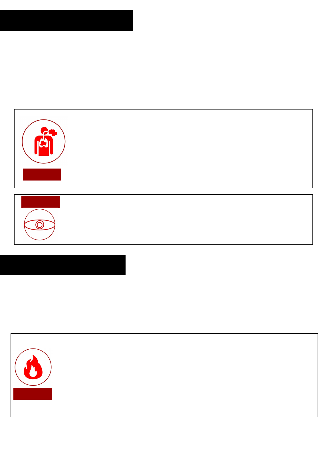
●Never engrave or cut any unknown material. The vaporization/melting of many
materials, including but not limited to PVC and polycarbonates, can give off hazardous
fumes. Please refer to the MSDS sheet from the material manufacturer to determine the
response of any work material to extreme heat (burning/fire hazard).
●Never operate the machine without a properly operating ventilation.
Most materials produce an irritating smoke when engraved. Some materials, including
but not limited to: paint, varnish, composition board, and plastics,toxic compounds.
General Safety
WARNING!
5
Safety During Operation
The output of the fiber engraving laser is fully contained in a Class 3 enclosure during normal operation.
However, the output beam is accessible to the operator during normal operation, giving the total system an
overall rating of Class 3B. Class 3 lasers have minimal safety concerns when used properly and handled with
care. The laser system is designated as Class 3B due to the fact that safety glasses must be used when
observing the laser engraving process.
Follow these Safety Guidelines at all times:
● Always use the provided safety glasses when looking at the laser.
●Never aim any laser towards an aircraft or vehicle that is in motion.
CAUTION!
Laser cutting and engraving systems can present a significant fire hazard due to the extremely
high temperatures generated by the laser beam. While the objective of most cutting and engraving operations
is to vaporize material without burning, most materials capable of being cut or engraved are inherently
combustible and can ignite. Usually this is a small flame of burning material issuing from the cut zone which
self-extinguishes due to the air assist or depowering of the beam. However, it is possible for the flame to
propagate and set fire to the machine and its surroundings.
Fire Safety
WARNING!
Always keep a properly maintained and inspected 5lbs. or larger fire extinguisher on hand.
Full Spectrum Laser recommends a Halogen or multipurpose dry chemical fire extinguisher.
Halogen extinguisher are expensive but easy clean, while the dry chemical extinguisher discharges
a sticky, corrosive powder that is very difficult to clean up.
Never operate your machine unattended. There is a significant risk of fire if set improperly, or if a
mechanical or electrical failure occurs while operating.
Always use the air assist, especially while vector cutting. The process is relatively slow and
applies a large amount of heat to the workplace. Vector cutting with the laser has the most
potential to create an open flame.

The power supply is capable of releasing a current up to 20mA. This power is sent to the discharge
terminals on the laser tube itself. In order to prevent access to bare wiring your laser shipped with silicone
terminal covers. Please notify Full Spectrum Laser support and immediately cease operations if the covers
ever slip and expose bare wire.
●Do not open any of the machine’s access panels while the unit is
plugged in. Opening a panel may expose the operator to the unit’s
power box, which is potentially lethal.
● Never make or break any electrical connections to the system
while the unit is turned on.
● Never access any electrical areas with hands or tools unless the
unit is disconnected from the power for at least one hour.
●Never replace the installed 20 amp fuse with one of a higher
rating. This will void your warranty and the electronics will not be
adequately protected from surges or short circuits.
●POWER ON/OFF is controlled by the switch at the back of the
machine. The machine is on when the (-) side is pressed and off when
the “o” side is.
● In case of a blown fuse always contact Technical Support before
replacing anything.
The standard for laser safety is the American Standard for the Safe Use of Lasers, Z136.12000. Developed by the American National
Standards Institute (ANSI) it is the basis for many federal regulations and Occupational Safety and Health Administration (OSHA) guidelines
for laser and laser system manufacturers. It contains detailed information concerning the proper installation and use of laser systems. While
the ANSI standard is not a law, its recommendations, including warning signage, training, and the designation of a laser safety officer, may
be mandatory under local regulations. It is the operator's responsibility to ensure that the installation and operation of the Full Spectrum
Desktop Laser System are performed following applicable laws. Copies of ANSI Standard Z136.12000 are available from:
LASER INSTITUTE OF AMERICA 12424 RESEARCH PARKWAY, SUITE 125 ORLANDO, FL 32826 (407) 3801553.
Electrical Safety
CAUTION!
Materials Fiber (1000W) Max Thickness
Carbon Steel 12mm (1/2”)
Stainless Steel 6mm (1/4”)
Galvanized Plates 3mm (1/8”)
Aluminum Plates 3mm (1/8”)
Copper Plates 2mm (5/64”)
7

WARNING!! The MC Fiber Flatbed models are over 6000lbs. A forklift is need to move this machine.
DO NOT ATTEMPT TO LIFT!!
Removing the Fiber Flatbed from Crate
Follow these instructions for best results:
1. Prepare Work Space: You will need an open, level work space to place your laser cutter. A well-
ventilated open room with at least 173" x 90" x 55" free is recommended. Be sure there is always a fire
extinguisher nearby in case of emergencies.
2. Open Crate. Use ⅜” socket or flat blade screwdriver to remove multiple 3” screws. A cordless impact
gun is recommended to decrease breakdown time. Remove the top panel, the top support bars, the left
and right sides, and lastly the front and back sides. Note this will require help for best results.
3. Remove Plastic Wrap and Foam. Remove the plastic wrapping and the foam from the machine.
4. Remove Machine from Crate. Remove machine from the crate bottom. With the laser unit now sitting
on the base of the crate, gently lift the machine off of the crate with a forklift.
5. Remove Protective Film. The machine will be covered in a protective Film. Remove it before
proceeding to anything else.
6. Remove Protective Covering. The protective covering on the back ends of the Flatbed must be
removed to access the Limit Stopper. Once removed the rubber can be slid out of the way.
7. Remove the Limit Stopper.
Section II. Crate Removal
8

8. Remove the Limit Stopper on the Other Side.
9. Ensure Machine is Level. Before completely lowering the machine, ensure that once the
machine is lowered it is level. If out of level, adjust height of threaded posts as needed until
machine is level. Lower machine onto feet.
10. Open the Laser head Compartment. Locate the key to open the laser head compartment. This
area need to be open for cable installation.
11. Opening Cable Connection. Open the cable covers to access the needed cables using a
Flathead Screwdriver (See below).
Note: For easy cable installation, make sure to remove the entire cable covering.
12. Open Side Panel.
9

This assembly is a simple process that should take less than half an hour to complete.
Section III. Installation & Assembly
Assembly Stages
1. Laser Box Installation
2. Laser Head Installation
3. Machine Connections
4. Operations Table Assembly
●Please be aware that the accessories will increase circuit load
The most significant power draw usually comes from the blower/exhaust
system. Consult the manufacturer’s information and manual for the
operating parameters of your exhaust system.
●The power inlet is equipped with a fuse to protect the machine from
surges or short circuits in case of emergencies. If this fuse ever
needs replacement, please contact Full Spectrum Laser technical
support.
NOTICE
10
Tools Needed:
Hex Keys
Flathead
Screwdriver

1. Install The Z-Axis Cover. Once installed remove the top layer of the covering for cable access.
2. Prepare Laser Box. Remove the side screws to open the side cover. Then remove the screws from
the top and remove the top cover.
3. Prepare Air Conditioner. Take out the Air Conditioning Unit and install onto the opening in the box.
Laser Box Installation
11

Laser Head Installation
Take out and set the laser generator onto the top shelf of the laser box. The laser generator should come
with a yellow fiber cable.
Note: The fiber cable if extremely delicate. It should not be bend or placed in areas that will
case high pressure. Do not tread on the fiber cable.
1. Install the fiber cable onto the laser starting from the cable access and proceeding along with the cables
until the side panel is reached (see below).
2. Pass the cable through the panel onto the X-gantry and then the Z-gantry.
3. The cable will be laser in the Laser head compartment. Make sure to remove the rubber and aluminum
cover from the fiber cable head.
4. Pull out the laser head.
12

4. The Fiber Cable and the laser head both have red dots on one side. Make sure to line up the dot before inserting
the cable head onto the laser head.
5. Once inserted turn the knob counterclockwise to tighten.
6. Install the Laser head onto the Laser Head Compartment using the screws located on the fitting.
7. Locate the signal, water and gas cables and run them through the Z-gantry into the Laser Head Compartment.
8. Connect the signal cable to the back port and the power cable to the front port.
9. Locate the water cables. Secure one end of a water tube to the blue cable and then onto the port below by
unthreading the screw and inserting them onto the cable.
10. Place the cable onto the port and thread the screw in place.
Signal Cable
Power Cable
13

11. Insert the second blue tube onto the adjacent port.
12. Insert the other end into the following port. (see below)
13. The third water tube will be placed onto the port on the left. Connect the other end to the port on the right below.
14. The final water tube will be connect to the final port and the black cable above.
15. A red gas tube will connect to the red cable and to the port at the very bottom of the laser head (see below).
14

15.Locate the following items for the next step.
16. Attach the signal amplifier onto the side of the laser head using the provided screws.(see below)
17. Insert the signal cable into the signal amplifier top port. Connect the high temperature cable to
the amplifier’s bottom port.
18. Insert the other end of the high temperature cable into the slot below.
Signal Amplifier
High Temperature
Cable
Screws
15

Machine Connections
Laser Box to Machine Connection
1. Insert the power cable into the laser generator and the machine.
2. Connect the signal cables to the laser generator (see below). Make sure that the
cables are in the correct position before plugging it into the machine.
3. Connect the ethernet cable next.
Water Chiller to Machine Connection
1. Locate the red, blue, and black cables on the machine.
2. Connect the black cable to the inlet and the blue cable to the outlet.
3. Connect the power cable into the water chiller and the machine.
4. Get out the white water tube and connect it to the low temperature outlet on the Water
Chiller. Connect the other end of the tube to the inlet of the Laser Generator.
5. Connect the second water tube to the low temperature inlet on the Water Chiller with
the outlet on the Laser Generator.
6. Locate a red tube. Connect one end of the red tube to the oxygen slot in the machine
and the other to the Oxygen Valve.
7. Connect the red cable from earlier onto the Nitrogen Valve.
8. Connect the machine to the power box. A yellow ground cable is also included.
Connect the yellow cable to the ground slot.
16

Operations Table Assembly
1. Take out the Operations Table and the connecting rods.
2. Remove the front right cover plate.
3. Pull out the Signal Cable and run it through the first connecting rod.
4. Install the rod onto the mount (see below).
5. Run the cable through the second rod and connect it to the first.
17

6. Open the back cover of the Operation Table and run the cables through the back cover.
7. Now connect the Power and VGA cables to the monitor.
8. Connect the Signal cable to the similar cable on the table.
9. Connect the USB cable to the USB port and plug in the wireless controller.
10. Place the wireless controller on the top of the back panel.
11. Lastly install the wireless receiver for the mouse into the USB Port.
PC Installation:
1. Open the Right Side Panel.
2. Place the computer inside.
3. Connect by ascending order (bottom to top): the power cable, the 62 pin signal cable, the 37
pin signal cable, the usb cable, the ethernet cable, and the VGA cable.
Congratulations. Your Flatbed is now ready to use.
18

Installation Instructions:
The MC Series Fiber Flatbed uses the software called CypCut. The software can be downloaded at
www.fscut.com. Before installing, make sure your system meets the following requirements to operate
the software.
CypCut System Minimum Requirement:
OS:WIndows 7
Processor: Intel i3
Memory: 4 GB Ram
Graphics: 15-pin VGA
Storage:73.2 MB
Follow the Setup Wizards instruction to install CypCut.
Once starting the Application it should look similar to the window below.
Section IV. Cypcut Software
19

Control Panel:
Jogging Controls -Moves the Laser Head Assembly along the
work area.
Laser Head Controls -Moves the Laser Head Up and Down
Cutting Parameters - Parameters than can be adjusted before
Running a project to obtain different results
Simu - Also known as the Simulation Button.
This button will show a simulation in the work area of how it will cut
out your material
Dry Run-
Runs the project without turning on the laser head. Ideal for making
final adjustment.
Start
Starts the project.
Pause
Pause the project. Selecting Start will resume where it left off.
Stop
Ends the project. Selecting start will resume project from the
beginning
Loop
Repeats the project the amount of times programmed.
CypCut Controls:
20
Table of contents
Other Full Spectrum Laser Industrial Equipment manuals

Full Spectrum Laser
Full Spectrum Laser MUSE MOPA User manual

Full Spectrum Laser
Full Spectrum Laser Muse Ultra User manual

Full Spectrum Laser
Full Spectrum Laser MUSE MOPA User manual

Full Spectrum Laser
Full Spectrum Laser MUSE TITAN V3 User manual

Full Spectrum Laser
Full Spectrum Laser Master Class CO2 Flatbed User manual
Popular Industrial Equipment manuals by other brands

MSG Equipment
MSG Equipment MS1000+ manual

VALSTEAM ADCA
VALSTEAM ADCA FLT17 Installation and maintenance instructions

Graco
Graco Ultra Max II ProContractor Quick operator's guide

ABB
ABB HT611062 Operation manual

Big Daishowa
Big Daishowa KAISER CK PRESETTER Operation manual

ABB
ABB HT613808 Operation manual