Furuno M12-05BM+05BF-010 Guide

Furuno CAN bus Network Design Guide
1
Furuno CAN bus Network Design Guide
This document describes the Furuno CAN bus and shows how to create Furuno CAN bus
networks and how to install Furuno CAN bus devices.
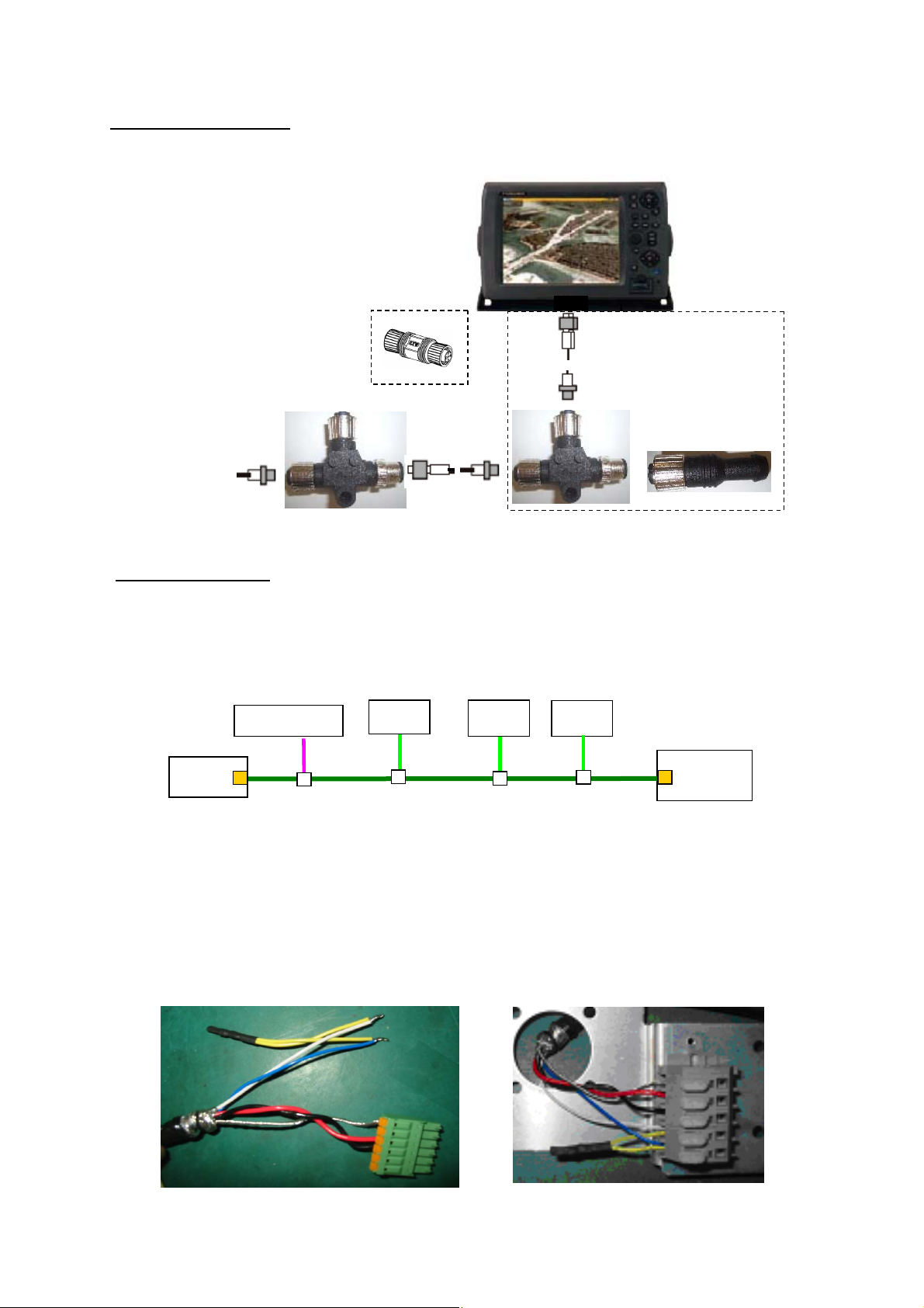
1. What is Furuno CAN bus?
Furuno CAN bus devices comply with NMEA 2000 physical and protocol standards, but these
devices can be installed in a slightly different way from the NMEA2000 standard to make a
network creation easier.
NMEA 2000
NMEA 2000 is a combined electrical and data specification for a marine data network for
communication between marine electronic devices such as depth finders, chartplotters, navigation
instruments, engines, tank level sensors and GPS receivers. NMEA 2000, a successor to the NMEA
0183 standard, connects devices using CAN (Controller Area Network) technology originally developed
for the automotive industry. CAN based networks were developed to function in electrically noisy
environments.
NMEA 2000 vs. NMEA 0183
NMEA 2000 is a serial data “network” operating at 250k bps and NMEA 0183 is a serial data “interface”
operating at 4.8k bps. NMEA 2000 networks allows multiple electric devices to be connected together
on a common channel for the purpose of easily sharing information.
Table 1 NMEA 2000 vs. NMEA 0183
NMEA 2000 NMEA 0183
Connector Standard connectors
(Plug and play)
Different connectors of each
manufacturer
Data rate 250k bits/second 4.8k (38.4k) bits/second
Compact binary message ASC II serial communication
Multi-talker, multi-listener Single-talker, multi-listener
Protocol
Network Serial communication
(Point to point communication)
CAN vs. Ethernet
NMEA decided to choose CAN to develop a low-cost, self-configuring, and multi-master network. The
table below shows other advantages of CAN over Ethernet.
Table 2 CAN vs. Ethernet
CAN Ethernet
Power Consumption Lower Higher
Bandwidth Low High
Collision Avoidance Yes No avoidance
(Collision detection)
Message Priority Yes No
Pub. No. TIE-00170-B

Furuno CAN bus Network Design Guide
2
Backbone
cable
Terminator
Furuno
CAN bus
Device
Drop cable
6 m (max.)
NMEA 2000
T-connector
+Vdc
Shield
Gnd
Terminator
Furuno
CAN bus
Device
Drop cable
Drop cable
1.2 Network Connections
Like a NMEA 2000 network, Furuno CAN bus networks consist of lengths of network
Backbone cable with a defined beginning and end. A resistive terminator (120 ohms, 1/4 W) is
connected at each end to reduce transmission-line reflections. See Fig.1.
Furuno Can bus devices are connected to the network backbone cable with a single Drop
cable. The maximum cable length of the drop cable is 6 m and the sum of the drop cables
should not exceed 60 m.
Power supply or battery connections are made to the network backbone cable either directly
or by means of a dedicated cable. Some Furuno CAN bus devices can power the network
through the network connector.
(15 Vdc recommended)
Fig.1 Typical Furuno CAN bus Network Topology
The T-connector is used to construct a Furuno CAN bus backbone and to extend the
backbone with appropriate lengths of backbone cable. The T-connectors can be separated by
the backbone cable or connected directly together. When constructing the network, take the
following into account;
1) Use one T-connector per device (see Fig.3).
2) Use the sides of the T-connectors to construct the backbone of the network.
(Furuno CAN bus device with an internal terminator is connected to the side of the
T-connector.) Fig.5
3) Use the top of the T-connector to attach a device.
Fig.2 Fig.3
Device
Device
Device Device

Furuno CAN bus Network Design Guide
3
Device
Device
Fig.4 Fig.5
Fig.6 Fig.7
Daisy Chain Connection Example
A Furuno CAN bus device, the FI-50, can be connected in daisy chain without the T-connector
as shown in Fig.8.
Fig.8 Daisy chain connection of FI-50 series
The network connection is made by two methods for all types of connections: a connector and
barrier strips. The connections are used;
(a) For connecting segments of backbone cable together
(b) For connecting terminations at the two ends of the cable
(c) For connecting the network power source, and
(d) For connecting devices.
Two types of the connector; “Mini” for heavy cable and “Micro” for light cable are used for
NMEA 2000 network connections.
Barrier strips are only recommended when the connections are made in a protected location,
or when they are installed in a weatherproof enclosure. Two methods may be used together in
the same network.
Device
Device
Device Device FI-50 FI-50 FI-50
Power supply
Terminator
Terminator
Terminator
Terminator

Furuno CAN bus Network Design Guide
4
Fig.9 shows a typical network connection made with barrier strips. When used for termination
resistors, all five wires are attached to the barrier strip and the termination resistor, 120 ohms,
1/4 W connected between NET-H and NET-L. No connections are allowed to the other
terminals.
Fig.9 Barrier strips
“Star” type connections are not allowed.
Fig.10 Barrier strip - Improper connection
1.3 Network Cable
Two types of cable are used in the network, heavy cable and light cable. The selection of
cable type for various portions (including the drop cable) of the network depends on the
number of Network loads attached, the length of the network cables, and the location of the
specific cable in the network.
Heavy cable
The heavy cable is five-wire constructed with two individually twisted-shielded pairs
enclosed by an overall shield with a shield drain wire connecting all three shields.
Table 3 shows the wire colors of the heavy cable (10 mm diameter, MAX. 8 A).

Furuno CAN bus Network Design Guide
5
Table 3 Wire colors of heavy cable
Name Pair Color Size Pin#
Shield Drain Bare 18AWG 1
NET-S Power Red 16AWG 2
NET-C Power Black 16AWG 3
NET-H Signal White 18AWG 4
NET-L Signal Blue 18AWG 5
Light cable
The light cable is five-wire constructed with two individually twisted-shielded pairs
enclosed by an overall shield with a shield drain wire connecting all three shields.
Table 4 shows wire colors of the light cable (6 mm diameter, MAX. 1 A).
Table 4 Wire colors of light cable
Name Pair Color Size Pin#
Shield Drain Bare 22AWG 1
NET-S Power Red 22AWG 2
NET-C Power Black 22AWG 3
NET-H Signal White 24AWG 4
NET-L Signal Blue 24AWG 5
1.4 Network Connector
Furuno CAN bus network uses NMEA2000 standard 5-pin connectors for the network
connections: “Mini” for the heavy cable and “Micro” for the light cable. Note that FI-50 series
uses the L-type Micro connector.
Table 5 and Figs.11 to 14 show Furuno CAN bus connector pin functions and face views.
These connectors comply with NMEA2000 LTW connector standard.
Table 5 Pin function of Furuno NMEA 2000 LTW connector
Pin No. Function Color
1 Shield Bare
2 NET-S (Power supply positive, +V) Red
3 NET-C (Power supply common, -V) Black
4 NET-H (CAN-H) White
5 NET-L (CAN-L) Blue
Fig.11 Female Mini connector
Fig.12 Male Mini connector
5
4
3
2
1
25.0 mm
1
2
3
4
525.0 mm
10 mm

Furuno CAN bus Network Design Guide
6
Fig.13 Female Micro connector
Fig.14 Male Micro connector
The following list shows the backbone/drop cables. To extend the backbone cable, use the
cable with a male connector on one end and a female connector on the other. For example, if
you need 15 meter cable, connect two 6 m cables, a 2 m cable, and a 1 m cable. Either heavy
cable or light cable is used as a backbone cable.
Note that the length of drop cable is 0 to 6 m.
Parts Name Type Code Number Connector fitted
CAN bus light cable (1 m) M12-05BM+05BF-010 000-167-962 Male and Female
CAN bus light cable (2 m) M12-05BM+05BF-020 000-167-963 Male and Female
CAN bus light cable (6 m) M12-05BM+05BF-060 00-167-964 Male and Female
CAN bus light cable (1 m) M12-05BFFM-010 000-167-965 Female
CAN bus light cable (2 m) M12-05BFFM-020 000-167-966 Female
CAN bus light cable (6 m) M12-05BFFM-060 000-167-967 Female
CAN bus heavy cable (1 m) CB-05PM+05BF-010 000-167-968 Male and Female
CAN bus heavy cable (2 m) CB-05PM+05BF-020 000-167-969 Male and Female
CAN bus heavy cable (6 m) CB-05PM+05BF-060 000-167-970 Male and Female
CAN bus heavy cable (1 m) CB-05BFFM-010 000-167-971 Female
CAN bus heavy cable (2 m) CB-05BFFM-020 000-167-972 Female
CAN bus heavy cable (6 m) CB-05BFFM-060 000-167-973 Female
Fig.15 CAN bus light cable Fig.16 CAN bus light cable
with a connector at both ends with a connector at one end
54
3
21
14.5 mm
3
21 5
4
14.5 mm
6 mm

Furuno CAN bus Network Design Guide
7
1.5 T-connector
There are two types of T-connectors: Mini for heavy backbone cable, Fig.17 and Micro for light
backbone cable, Fig.18.
Parts Name Type Code Number Remarks
Mini T-connector NC-050505-FMF-TS001 000-160-507 for heavy cable
Micro T-connector SS-050505-FMF-TS001 000-168-603 for light cable
Fig.17 Mini T-connector Fig.18 Micro T-connector
(NC-050505-FMF-TS001) (SS-050505-FMF-TS001)
1.6 Terminator
Furuno CAN bus 120-ohm terminators are available with the following part numbers. The
terminator should be attached at each end of the backbone cable.
The terminator has a 120-ohm resistor across pins #4 and #5.
Parts Name Type Code Number Remarks
Male terminator LTWMN-05AMMT-SL8001 000-160-508 Mini connector, Fig.19
Female terminator LTWMN-05AFFT-SL8001 000-160-509 Mini connector, Fig.20
Male terminator LTWMC-05BMMT-SL8001 000-168-604 Micro connector, Fig.21
Female terminator LTWMC-05BFFT-SL8001 000-168-605 Micro connector, Fig.22
Fig.19 Male terminator for heavy cable Fig.20 Female terminator for heavy cable
Fig.21 Male terminator for light cable Fig.22 Female terminator for light cable
Female Female
Female, Micro Female
Male Male

Furuno CAN bus Network Design Guide
8
Termination with MFD
The MFD unit is terminated with a terminator as shown in Fig.23, because the unit does not
have the internal terminator.
Fig.23 Termination with MFD
Internal Terminator
Furuno CAN bus devices, DRS, FI-50, GP-330B, SC-30, and WS-200 have an internal
terminator, so these devices can be connected to the backbone cable as shown in Fig.24.
By connecting the device to the backbone cable, the cable length between the T-connector
and the device can be extended more than 6 m.
Fig.24 Using internal terminator at both ends of backbone cable
To activate the internal terminator;
(a) DRS
The resistor assembly, 120 OHM-1007#24-L50, C/N: 000-167-746 is connected between
#5 and #6 of J603 in the radome antenna and #4 and #5 of TB102 in the open type
antenna.
Fig.25 Terminator in DRS2D/4D Fig.26 Terminator in DRS4A/6A/12A/25A
GP-330B
Device Device Device
FI-50
Power supply
J603
TB102
CAN bus cable o
r
NMEA2000 cable
Female Terminator
Backbone cable
to rest of bus
In-line Terminator
Type: FRU-0505-FF-IS
C/N: 000-172-037-10
#5 & #6
#4 & #5
o
r

Furuno CAN bus Network Design Guide
9
(b) GP-330B
The supplied contact pin, 05-251-01 (C/N: 000-168-935) is inserted into socket #5 in the
connector before connecting it to the antenna.
Fig.27 Termination on GP-330B
(c) WS-200
The same contact pin as GP-330B is used for termination. (Type: 05-251-01)
(d) SC-30
Use the cable, MJ-A10SPF0015-15/30 of which 10-pin MJ connector has a 120-ohm
resistor connected between pins #4 and #5.
>1> Drain
>2> RED
>3> BLK
>4> WHT
120-ohm resistor
>5> BLU
>6>
>7>
>8> PPL
>9> YEL
>10> GRN
Fig.28 Termination on SC-30
(e) FI-50
The terminal resistor is on and off through “Setup2” menu. To show setup2 menu, press
following two keys at a time until the menu appears.
FI-50 series To get into Setup2 mode, press To choose item, press
FI-501/502/505 3rd and 4th keys from left MODE
FI-503 LOWER and SELECT/CLEAR Upper
FI-504 APP/TRUE and SELECT/CLEAR DISP
FI-506 BRILL and Left arrow key
(To save the change, press BRILL
and Left arrow key again.)
Right arrow key
Contact pin
MJ-A10SPF0015
Connector has
a resistor.

Furuno CAN bus Network Design Guide
10
1.7 Network Power Supply
The Furuno CAN bus network devices operate at 9.0 to 16.0 Vdc. Ensure that the voltage of
power supply to the device located farthest from the power source on the network is 9.0 Vdc
or more.
The total current carrying capacity of the network depends on the choice of backbone cable
and where the power is connected into that cable. The heavy cable is rated at 8 Amps and the
light cable is rated at 1 Amp. Both of these ratings are at 20 degrees Celsius and must be
de-rated with temperature. If the power connection is made to the center of the backbone
cable, then the current carrying capacity is effectively doubled as the full capacity is available
to each end of the network from the power connection point.
For CAN bus network with DRS
The DRS series outputs 15 Vdc, 1A from the network port to the CAN bus devices in the
network. The power supply cable connection to the network is not necessary when the DRS is
in the network. The power connection is at either the end or middle of the network.
Note that the pin assignment of the network port differs between radome and open antennas.
J603 in Radome Antenna TB102 in Open Antenna
Pin No. Signal name Remarks Pin No. Signal name Remarks
1 SHIELD 1 SHIELD
2 NC 2NET_S V+ (+15V)
3 NET_S V+ (+15V) 3 NET_C V-
4 NET_C V- 4 NET_H CAN_H
5 NET_H CAN_H 5 NET_L CAN_L
6 NET_L CAN_L
The number of the devices that can be connected to the network powered from the DRS
depends mainly on the network load. For example, Weather Station, WS-200 and Satellite
Compass, SC-30 are not connected to the DRS via CAN bus at the same time due to
overload. The following section describes the network load calculation.
Fig.29 Furuno CAN bus powered from DRS
(No network power cable required)
When both the SC-30 and WS-200 are connected to the network with the DRS, disconnect
pins 3 and 4 of J603 on the CAN bus interface board, 03P9462 in the DRS and connect an
external 15-Vdc power supply to the network backbone cable.
15 Vdc, 1A
GP-330B WS-200 SC-30
Combination: YES YES NO
YES NO YES

Furuno CAN bus Network Design Guide
11
Device Power supply
“DATA2”
“NMEA2000”
MFD
Fig.30 shows the simplified circuit diagram of power supply circuit on the CAN bus interface
board, 03P9462. The circuit is protected by a 1.5 A onboard fuse.
From PWR PCB J603
J602 >5> Net_H
+15VH>1> >6>Net_L
+15 V C >2> >3> Net_S (+15 V)
>4>Net_C
Fig.30 CAN bus interface board in DRS
For CAN bus network with MFD
The Furuno CAN bus network is powered through the MFD unit: the power supply or battery is
connected to pins #17 (NET_S_IN) and #18 (NET_C_IN) of 18-pin “DATA 2” connector on
MFD8/12/BB with a 1-A in-line fuse and switch. See Figs 31 and 32.
The output voltage of the power supply is ideally 15 Vdc +/-5%, ripple 0.25 Vp-p or less as
NMEA2000 standard, considering input line variation and DC drop in the network power cable.
Do NOT connect the network to a 24 Vdc power supply.
“Isolation” from other devices power and grounds of the power supply must be maintained.
Fig.31 Connection of power supply to network through MFD
Fig.32 Connection of network power supply to MFD
18-pin pigtail cable for DATA 2 port
Type: FRUDD-18AFFM-L180
C/N: 000-164-608
1 amp Fuse and
in-line switch
(Local supply)
Light green
Pin #18
Pink
Pin #17
To network bus
(11.6Vdc, 1A with a 12 Vd
c
power supply connected)
10 Vdc to 16 Vdc,
1 amp Maximum
+ _
12 to 24 Vdc for MFD
Regulator
U13
F1 (1.5 A)
03P9462 VCC_CAN

Furuno CAN bus Network Design Guide
12
RD-33
NMEA0183 NMEA0183 NMEA0183
MFD
NMEA0183
(MAX. 3 units)
NMEA-CAN bus
Interface unit
IF-NMEA2K1
Device
Power supply
A diode and a polyswitch (SMDC110F) on CONT2 board in the MFD unit protect the interface
circuit against over-current and short-circuit. See Fig.33.
J3DATA2 J702 J501 J4NMEA2000
NET_S_IN>17> >1> >1> >2>NET_S
NET_C_IN >18> >2> >2> >3> NET_C
>3> >3> >4> NET_H
>5> NET_L
Fig.33 Protection of network power circuit in MFD
The maximum length of the network backbone is 150 m when the heavy cable is used and 50
m when the light cable is used. More details are explained in the “CAN bus Network
limitations” section.
1.8 Network Grounding
The network is grounded at a SINGLE location. This is normally done at the power supply
connection to the network and should be well connected to the vessel’s grounding system.
There must be no other ground connections on the network to avoid the problem of ground
loops, which can harm the network performance.
1.9 Connecting NMEA 0183 Device
An NMEA 0183 device is connected to the CAN bus network via MFD unit or by using
NMEA2000 Interface unit, IF-NMEA2K1.
Fig.34 (a) Connection of NMEA0183 to CAN bus network
with MFD and IF-NMEA2K1
The remote display RD-33 is also capable of converting the NMEA0183 signal to the CAN
bus signal.
Fig.34 (b) Connection of NMEA0183 to CAN bus network with RD-33
CONT1
CONT2
1.1A
NMEA0183
Terminator
Terminator

Furuno CAN bus Network Design Guide
13
1.10 CAN bus Network Limitations
When building a CAN bus network, keep in mind following limitations.
1.10.1 Single MFD in CAN bus network
Single MFD or DRS unit, one of MFD8, MFD12, MFDBB, and DRS is connected to a Furuno
CAN bus network. Do NOT connect two or more MFD and/or DRS to the Furuno CAN bus
network. The DRS and MFD units are connected each other via Ethernet.
Fig.35 Single MFD or DRS in Furuno CAN bus network
1.10.2 Backbone Cable Length
Load Equivalency Number (LEN)
Like NMEA2000, the power rating of the Furuno CAN bus device is specified as a Load
Equivalency Number, or LEN and used in planning network installations. One network load is
defined as 50 mA or any portion thereof (e.g., a device taking 51 mA from the network power
bus is a Two LEN device). A LEN of 4 means that the device consumes up to 4 x 50 mA = 200
mA.
Table 6 shows the LEN of Furuno CAN bus devices.
Table 6 LEN of Furuno CAN bus devices
Model MFD BB MFD 8/12 SC-30 GP-330B WS-200 FI-50 series*
LEN 1 1 10 3 13 2
*: FI-501/502/503/504/505/506
Use Tables 7 and 8 to find the maximum length of the backbone cable. First calculate the total
LEN of the devices in the network. In the example of Fig.36, the total LEN is 1+ 1 + 2 +2 = 6.
Then, find the maximum cable length for the LEN of 6 in Table 7 or 8: 150 meters for heavy
cable and 50 meters for light cable when the network is powered from 15 Vdc power supply.
When the network is connected to 12 Vdc power supply, the maximum cable length is about
half the value in Tables 7 and 8.
Fig.36
CAN bus
Device
LEN = 1
CAN bus
Device
LEN = 1
CAN bus
Device
LEN = 2
CAN bus
Device
LEN = 2
Power supply
Power supply MFD
(
DRS
)
Device
MFD
(DRS)

Furuno CAN bus Network Design Guide
14
Practically, total LEN in the network is less than 20, so the overall cable length can be
extended up to 150 m with heavy cables and 15 Vdc power supply.
When both heavy and light cables are used in the network as shown in Fig.10, the length of
cable B is calculated by using the following formula.
B = (X – A )/4
Where, X is the maximum cable length obtained from the table.
Fig.37
Assuming that the total LEN in the network is 50 and the heavy cable length, A is 40 m;
B = (80 m – 40 m) / 4 = 10 m
When power supply is connected to the middle of the network as shown in Fig.38, the cable
length of A and B is determined individually. For example, if the total LEN of devices attached
to the cable A is 75, the maximum length of cable A is 50 m from Table 7. Do the same for B.
The total length of cables A and B is less than 150 m.
Fig.38 Middle-powered CAN bus network
When the power cable is connected to both ends of the network, the cable length is double
the value obtained from the table. In any case, the cable length does not exceed 150 m. For
example, the maximum cable length is 150 m, even if the calculated value is 180 m.
Note that power supplies are isolated and the shield connection is made at only one power
supply (single-point ground) in multiple power supply configuration. Do NOT use a
combination of battery and power supply connections.
Fig.39 Multiple power supply configuration
A
Power supply
B
A
= 40 m B
Power supply
Heavycable Lightcable
Device Device
Device Device
Power supply
Power supply
Device

Furuno CAN bus Network Design Guide
15
1.10.3 Drop Cable Length
The total drop cable length must not exceed 60 m and no single drop cable should exceed 6
m.
1.10.4 Device Limitation
No more than 20 (LEN) CAN bus devices can be connected to the Furuno CAN bus network
powered from the DRS and through the MFD unit.
The total LEN of the devices connected to the heavy backbone cable should not exceed 160
and 20 for the light backbone cable.
Table 7 Total LEN vs. Heavy backbone cable length (Power source: 15 Vdc *)
Total
LEN
Max.
(m)
Total
LEN
Max.
(m)
Total
LEN
Max.
(m)
Total
LEN
Max.
(m)
Total
LEN
Max.
(m)
< 20 150 46 80 72 55 98 40 124 30
21 150 47 80 73 55 99 40 125 30
22 150 48 80 74 50 100 40 126 30
23 150 49 80 75 50 101 40 127 30
24 150 50 80 76 50 102 35 128 30
25 150 51 70 77 50 103 35 129 30
26 150 52 70 78 50 104 35 130 30
27 140 53 70 79 50 105 35 131 30
28 140 54 70 80 50 106 35 132 30
29 130 55 70 81 50 107 35 133 30
30 130 56 70 82 45 108 35 134 30
31 130 57 70 83 45 109 35 135 30
32 120 58 65 84 45 110 35 136 30
33 120 59 65 85 45 111 35 137 25
34 110 60 65 86 45 112 35 138 25
35 110 61 65 87 45 113 35 139 25
36 110 62 65 88 45 114 35 140 25
37 100 63 60 89 45 115 35 142 25
38 100 64 60 90 45 116 35 144 25
39 100 65 60 91 40 117 30 146 25
40 100 66 60 92 40 118 30 148 25
41 90 67 60 93 40 119 30 150 25
42 90 68 55 94 40 120 30 152 25
43 90 69 55 95 40 121 30 154 25
44 90 70 55 96 40 122 30 156 25
45 80 71 55 97 40 123 30 160 25
*: When 12 Vdc power source is connected to the network, divide the cable length in halves.

Furuno CAN bus Network Design Guide
16
Table 8 Total LEN vs. Light backbone cable length (Power source: 15 Vdc *)
Total LEN Max. (m) Total LEN Max. (m) Total LEN Max. (m)
<18 50 19 50 20 45
*: When 12 Vdc power source is connected to the network, divide the cable
length in halves.
1.11 Adding a New Device
A new device is added to a working network bus by using the following procedure. First, add
an additional T-connector anywhere along the network backbone where a connection already
exists. The connection is at the end of the network (between a T-connector and a terminator),
between two T-connectors, between a T-connector and a backbone extension cable, or
between two extension cables. Separate the connectors of the old connection and attach new
T-connector between them. Then, connect the device to the T-connector by using a drop
cable.
There are a few things to consider:
1) Voltage drop between the power source and the device located farthest from the power
source is 3.0 Vdc or less when 12 Vdc battery is used.
2) Total network load must be considered. When the network is powered though the MFD
and from the DRS, total LEN is 20 or less.
3) The network is terminated to function correctly.
1.12 Using Junction Box FI-5002
By using FI-5002 Junction Box, Furuno CAN bus is designed without T-connectors and
terminators. The FI-5002 has 120-ohm terminal resistors, six terminal blocks for the
connection of up to 6 devices, and two terminal blocks for the connection of backbone cables
for network expansion. The junction box is not waterproof.
Fig.40 shows simplified schematic diagram of FI-5002. A three-way terminal block is used for
the network power connection.
Fig.40 Connection of terminal blocks in FI-5002
#1 Shield
#2 NET-S
#5 NET-L
#3 NET-C
#4 NET-H
CN1 CN3 CN4 CN5 CN2
To power supply To device (CN3 to CN5) To backbone cable and/or
(12 Vdc, 2A MAX) FI-5002 (or not used)

Furuno CAN bus Network Design Guide
17
Fig.41 shows a typical Furuno CAN bus network by using a junction box FI-5002.
Fig.41 Typical connection on FI-5002
To connect the internal termination resistor to the end of the network bus, set the jumper block
as below.
1) When no backbone cable is connected, R1 and R2 are set to ON position.
2) When one backbone cable is connected, either R1 or R2 is set to ON position.
3) When two backbone cables are connected, R1 and R2 are set to OFF position.
Fig.42 Internal terminators in FI-5002
The FI-5002 is added anywhere along the network backbone. A maximum of three FI-5002 is
connected in series.
Fig.43 Network with FI-5002 and T-connector
R2 R1
: Internal terminator
FI-5002
CN1 CN2 CN3 to CN5 CN2
Device Device
12 Vdc (Max. 6 devices)
MAX. 6 m
: Resistor is disconnected. (OFF)
: Resistor is connected. (ON)
Jumper block
CN1
CN3 CN4 CN5 CN2
Backbone
cables
Drop cables
PWR
cable
Device
Device
FI-5002
CN2 CN2
12 Vdc T-connector
Terminator
Device

Furuno CAN bus Network Design Guide
18
FI-5002 FI-5002
FI-5002
CN2 CN2 CN2 CN2
CN2 CN2
12 Vdc
FI-5002
CN2 CN2
Device
Device
Device
12 Vdc T-connector
Terminator
Device
Terminator
Fig.44 Network with two terminators connected to T-connectors
Fig.45 Three FI-5002 in network
1.13 NavNet Bridge
Two or more CAN bus networks can be connected by using MFD and DRS via Ethernet as
shown in Fig.46. All devices share the sensor data in the network. The connection of the
DRS having a CAN bus network to the MFD in the bridge eliminates the duplication of the
cable run to the sensors outside.
Fig.46 Simplified NavNet Bridge connecting two CAN bus networks
Device
Device
Device
Device
Power supply
CAN bus network (2)
Device DRS
CAN bus network (1)
Ethernet
Outside brid
g
e
Device
MFD8/12/BB

Furuno CAN bus Network Design Guide
19
More complex networks are designed by using a network Hub, HUB-101 as shown in Fig.47.
Fig.47 Two or more MFD in network
The number of devices that can be connected to the network is;
DRS series: 2 units
HUB-101: 3 units
MFD8/12/BB: 10 units
RD-33: 3 units in CAN bus
The MFDBB has a built-in 4-port Hub, so up to two HUB-101’s are connected to the network
with a MFDBB.
The Ethernet ports 1 and 2 are designed to output power to the control units, DCU12 and
MCU-001. Do NOT connect MFD8/12 to ports 1 and 2, otherwise MFD8/12 in the earlier
production may be damaged. MFD8/12 in the current production has the protection circuit.
Fig.48 MFDBB, rear view
Smart Sensor, DST-800
SC-30
DRS
DFF-1/3
PSU-012
HUB-101
MFD
MFD
MFD
CAN bus (1)
Ethernet
12-24 Vdc
T-connector
Instrument, FI-50 series
CAN bus (2)
12 Vdc for CAN bus
See Fig.49.

Furuno CAN bus Network Design Guide
20
Fig.49 RJ45 jacks for Ethernet connection on MFDBB
Table 9 Pin assignment of built-in Hub of MFDBB
NETWORK 1 & 2 NETWORK 3 & 4
#1 E_TD_P E_TD_P
#2 E_TD_N E_TD_N
#3 E_RD_P E_RD_P
#4 SW_P SW_P
#5 SW_N SW_N
#6 E_RD_N E_RD_N
#7 PWR_SW_N N.C.
#8 PWR_SW_P N.C.
Power Synchronization
Power on/off synchronization amongst all of the NavNet 3D display units can be
achieved when the dedicated Ethernet hub HUB-101 is used. Set the corresponding
DIP switch in the HUB-101 to ON position to activate this feature.
Fig.50 HUB-101 with cover removed
1234 5678
DIP switches #1 to #8
for ports 1 to 8, from left
This manual suits for next models
35
Table of contents
Other Furuno Cables And Connectors manuals