Furuno IF-8540 User manual

www.furuno.com
All brand and product names are trademarks, registered trademarks or service marks of their respective holders.
This information provides the installation instructions for the junction box IF-8540. The units pre-installed in the junc-
tion box change depending on the configuration purchased.
A: one MC-3000S-N and three MC-3020D-N
B: one MC-3000S-N and four MC-3020D-N
C: one MC-3000S-N, three MC-3020D-N and two MC-3010A-N
A maximum of six sensor adapters can be installed in the junction box (MC-300S-N included). In the case of config-
urations A and B, you can install the optional MC-3010A-N and MC-3020D-N additionally. When an additional unit
is installed, prepare the optional sensor adapter and cable assy.* as shown below.
*:Forpowersupplyanddatacommunication, it is necessary to connecta cable assy. between sensor adapters.One
cable assy. is necessary per each additional unit.
• Sensor Adapter (Type: MC-3010A-N, no coating, for analog input)
• Sensor Adapter (Type: MC-3020D-N, no coating, for digital input)
• Cable Assy. (Type: AI.14-8AI.34-6L1000, Code No.: 000-177-250-10)
Thetable shownbelowindicates includeditems inthejunction box.Thequantity ofincluded itemschanges
depending to the configuration purchased.
A: one MC-3000S-N and three MC-3020D-N
B: one MC-3000S-N and four MC-3020D-N
C: one MC-3000S-N, three MC-3020D-N and two MC-3010A-N
Name Type Code No. Qty Remarks
ABC
Junction Box IF-8540 - 1 1 1
Cosmetic Cap CP-30BC-10-BLACK 000-179-377-10 2 2 2
Cable Band PLF1M-M 000-116-921-10 27 27 27
Rod Terminal AI 1,5-6 BK 000-176-412-10 10 10 10 For DPYC-1.5 cable
AI 1-6 RD 000-176-413-10 60 80 60 For MPYC-12 cable
AI 0,75-6 GY 000-176-411-10 40 40 60 For TTYCSLA cable
Crimp-on Lug FV2-4 BLU 000-157-247-10 1 1 1 For grounding the IF-8540
FV1.25-4(LF) RED 000-166-666-10 9 9 15 For drain wire of TTYCSLA cable
Spare Fuse FGMB 125V 3A PBF 000-157-481-10 3 3 3 For MC-3000S-N
Installation Instructions
JUNCTION BOX
Model IF-8540
Included Items1

2
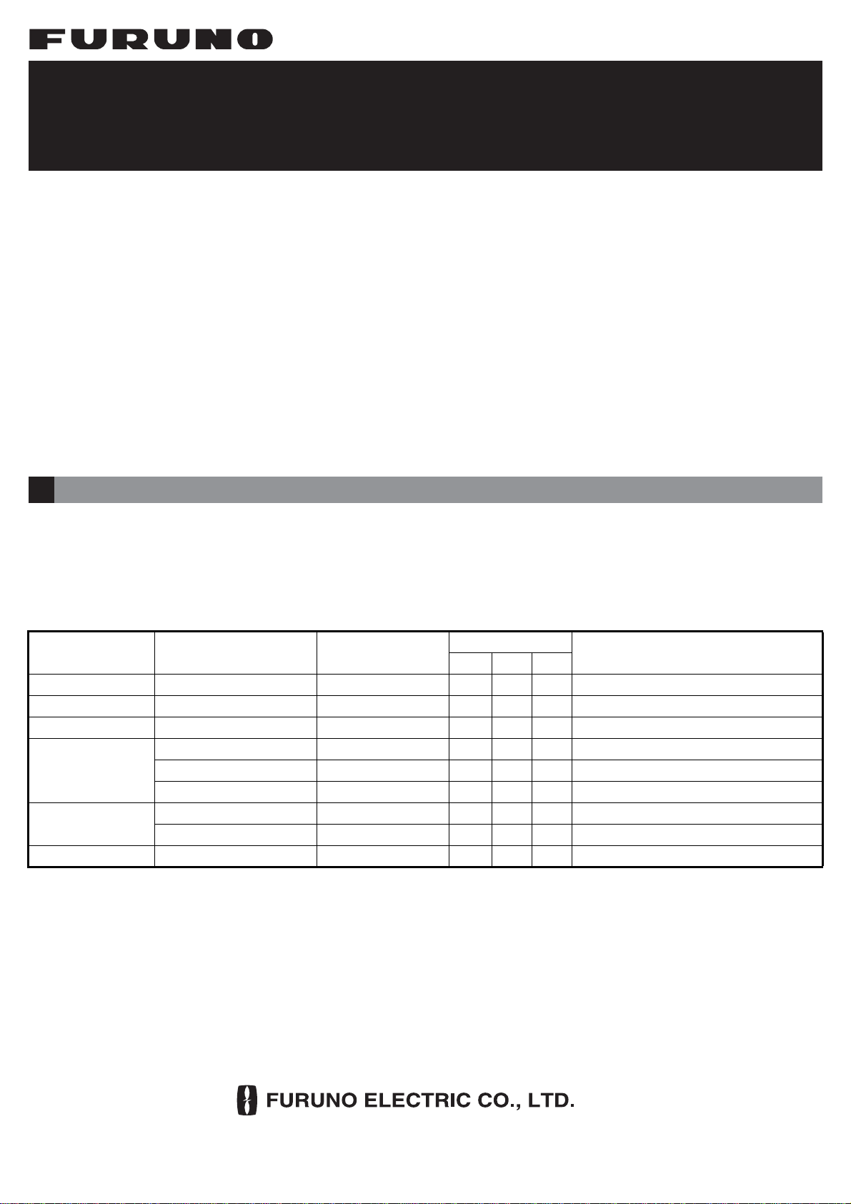
Prepare the materials and tools shown below to install the junction box.
*: Many of the of the cables mentioned are JIS (Japanese Industrial Standards) cables. If not available locally, use
the equivalent. For details of the JIS cables, see the cable guide in the installation manual of the VDR (IME-44850).
Select a mounting location, keeping in mind in the following points:
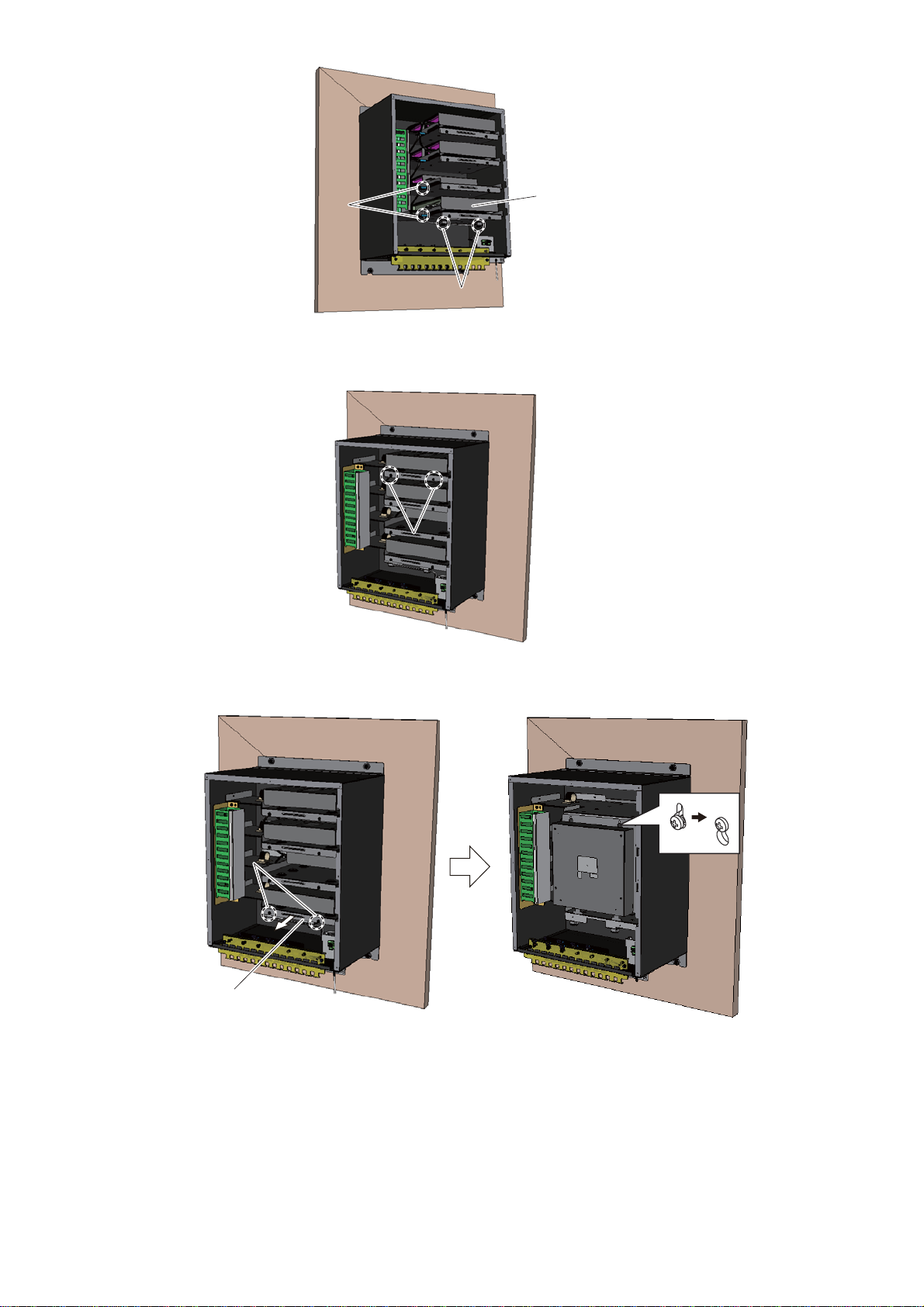
Install the junction box on a bulkhead.
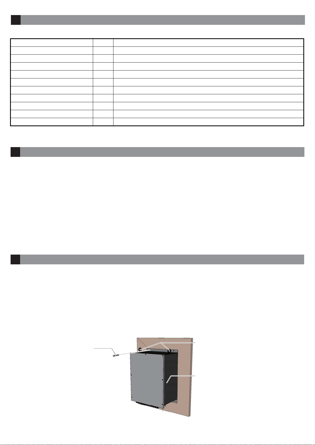
1. Drill four pilot holes in the bulkhead for M10 bolts (or 10 coach screws).
2. Screw in two bolts (local supply) at the bottom two pilot holes, leaving approx. 5 mm of the bolts exposed.
3. Hang the unit on the two bolts screwed in at step 2.
4. Screw in two bolts (local supply) at the top of the unit.
5. Fasten all bolts to fix the unit.
6. Remove two eye bolts at the top of the unit, then attach two cosmetic caps (supplied) to eye bolts holes.
Name Qty Remarks
M10 Bolt 4 For fixing junction box. Coach screws (10) can be also used.
FR-FTPC-CY Cable 1 For LAN connection with DCU (VR-7010)
Ground Wire 1 IV-2sq.
DPYC-1.5 Cable* 1 For power connection (24 VDC)
TTYCSLA Cable* - For analog input
MPYC-12 Cable* - For digital input
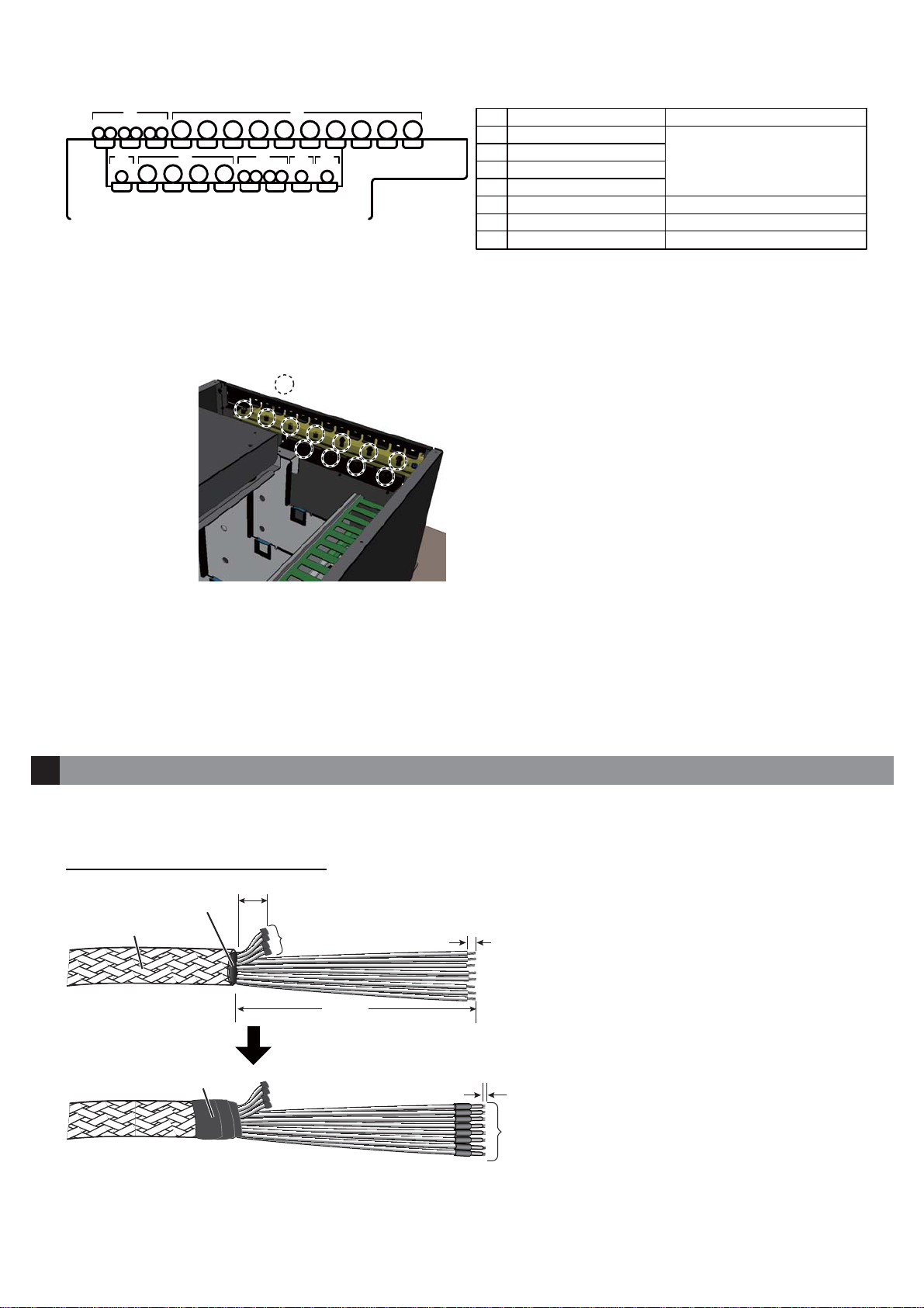
Heat Shrink Tubing - For drain wire of TTYCSLA cable
Cable Tie - For fixing cables
Vinyl Tape - For cable protection
Crimping Tool 1 For attaching rod terminals (Type: CRIMPFOX 10S)
• Locate the unit away from heat sources.
• Select a location where the shock and vibration are minimal.
• Locate the unit away from places subject to water splash
and rain.
• Make the maintenance space shown in the outline drawing
at the middle of this manual for maintenance and checking
purpose.
• Select a mounting location considering the length of the
cables to be connected to this unit.
• Select a location that is strong enough to support the weight
of the unit.
• The cable entrance of the unit must face downward.
• A magnetic compass will be affected if the unit is placed too
close to the magnetic compass. Observe the compass safe
distances to prevent interference to a magnetic compass.
MC-3000S-N: 2.05 m (standard), 1.35 m (steering)
MC-3010A-N: 0.75 m (standard), 0.50 m (steering)
MC-3020D-N: 1.05 m (standard), 0.70 m (steering)
• Select a location where the surface is flat. Ifit is not flat, insert
a number of washers between the unit and the mounting
location as necessary.
Required Materials and Tools2
Mounting Considerations3
Mounting the Junction Box4
M10 bolt
(or coach screw)
Junction box
Eye bolt

3
Install the additional sensor adapter(s) (MC-3010A-N and MC-3020D-N) at the locations “E” and “F” indicated in the
figure below. The unit may be pre-installed at the location “E” and “F”, depending the configuration purchased.
1. Unfasten seven binding screws (M4×10) to remove the junction box cover.
2. Release the internal wiring cable from the wire saddle.
3. Slightly loosen two binding screws (M4×10) to pull out the fixing plate.
Note: Loosen the binding screws only enough to pull out the fixing plate. If the screws are loosened too much,
the plate may fall and be damaged when it is hung in the next step.
Mounting an Additional Sensor Adapter(s) (Option)5
䕆㻌5-1 Mounting an Additional Sensor Adapter(s)䕆㻌5-1 Mounting an Additional Sensor Adapter(s)
• A: MC-3000S-N*1
• B to D: MC-3020D-N*1
• E and F: Mounting location for additional unit*2
A
B
C
DE
F
Front
No use *1: Pre-installed in the junction box.
*2: Additional unit can not be installed when the pre-installed
unit(s) exists.
Binding screw
䠄7 pcs䠅
Junction box cover
Wire saddle:
Release the cable from this wire
saddle to install the first additional
unit.
Wire saddle:
Release the cable from this wire
saddle to install the second
additional unit.
Wire saddle:
Release the cable from this wire
saddle to install the second
additional unit.

4
4. Hang the plate to the screws loosened at step 3.
The figure below is an example for the first additional unit.
5. Unfasten four binding screws (M4×10) to remove the additional sensor adapter cover.
6. Fix the unit to the fixing plate with four binding screws (M4×10, supplied with sensor adapter).
7. Connect the optional cable assy. (AI.14-8AI.34-6L1000) between sensor adapters.
The internal wiring between sensor adapters in the junction box is as shown in the figure below.
8. See“8.WiringforMC-3000S-N”(page7)and “9.Wiringfor MC-3020D-Nand MC-3010A-N”(page 9)to connect
the cable from the external equipment to the sensor adapter.
9. See “5-2. Setting the Termination Resistor and Modbus Address” (page 5) to set the termination resistor and
Modbus address.
Fixing plateFixing plate
Unfasten these binding screws
to pull out the fixing plate.
Unfasten these binding screws
to pull out the fixing plate.
Binding screw
(4 pcs)
Binding screw
(4 pcs) Sensor adapter
(MC-3010A-N or
MC-3020D-N䠅
Sensor adapter
(MC-3010A-N or
MC-3020D-N䠅
J1
24 VDC
MC-3000S-N
MC-3020D-N
MC-3020D-N
MC-3020D-N First additional unit*
Second additional unit*
J2
J1
J1
J2
J1
J2
J1 J2 J1 J2
J1
Front
*: The unit may be pre-installed and the internal
wiring completed depending on the configuration
purchased.

5
10. Reattach the sensor adapter cover.
11. Insert the fixing plate to the original location, then fasten two binding screws loosened at step 3.
12. Fix the internal wiring cable released at step 2 with the wire saddle.
13. Check the checkmark(s) on the label on the rear side of the junction box cover, according to the additional
unit(s).
14. Reattach the junction box cover.
When an additional sensor adapter(s) is installed, set the termination resistor and Modbus address.
• Termination resistor: Use the jumper block J25 to set the termination resistor ON/OFF. For the first and last sensor adapter
in a series, short between 1 and 2 pin to set the termination resisitor ON. For other sensor adaper, short between 2 and 3 pin
of to set the termination resisitor OFF.
• Modbus address: Use the rotary switch U18 to set the Modbus address number.
Check the checkmark(s)
according to the additional unit(s).
The label on the rear side of the junction box cover
䕆㻌5-2 Setting the Termination Resistor and Modbus Address䕆㻌5-2 Setting the Termination Resistor and Modbus Address
J25 J25
MC-ANLG board (24P0115, MC-3010A-N)MC-DIN board (24P0116, MC-3010A-N)
U18
U18
A
B
C
DE
F
Front
Location
D
E
Terminal resistor (J25)
Short between 2 and 3 pin (termination resistor: OFF).
Short between 1 and 2 pin (termination resistor: ON).
Modbus address (U18)
Keep the default setting.
“Set to “4”
.
Location
D
E
F
Terminal resistor (J25)
Short between 2 and 3 pin (termination resistor: OFF).
Short between 1 and 2 pin (termination resistor: ON).
Modbus address (U18)
Keep the default setting.
Set to “4”
.
Set to “5”
.
When additional unit is installed at the location “E” only (
“F” is not used)
When additional unit is installed at both location “E” and “F”

6
Power for the junction box (24 VDC) is supplied from the DCU (VR-7010). Use the DPYC-1.5 (local supply) to con-
nect between the J1 port on the junction box and J313 port on the DCU. For wiring the DCU, see the installation
manual of the VDR (IME-44850).
1. Fabricate the DPYC-1.5 cable as shown below.
2. Unfasten seven binding screws (M4×10) to remove the junction box cover.
3. Pass the wires through the cable entrance, then connect them to the J1 port.
4. Fix the cable to the cable clamp, using a cable tie (local supply).
Note: The armor of the cable should contact the cable clamp.
5. Reattach the junction box cover.
Power Supply (24 VDC)6
6 mm
Armor SheathSheath
80 mm
Vinyl tape (Width: 20 mm) 0.5 to 1 mm
Crimp the rod terminals (AI1.5-6
BK, supplied), using the crimping
tool (CRIMPFOX 10S). After
crimping, confirm that the 0.5 to
1 mm of the wires are exposed.
J1 portJ1 port
OpenerOpener
Insert the wire while pushing the
opener.
䠇䠇䠉䠉
Fix the cable to the cable
clamp, using a cable tie.
Fix the cable to the cable
clamp, using a cable tie.

7
Attach the crimp-on lug (FV2-4 BLU, supplied) to the ground wire (IV-2sq., local supply), then fix it to the ground
terminal.
Connect the external equipment to the MC-3000S-N, using the TTYCSLA and FR-FTPC-CY cables.
1. Fabricate the TTYCSLA and FR-FTPC-CY cables as shown below.
TTYCSLA cable
FR-FTPC-CY cable
2. Unfasten seven binding screws (M4×10) to remove the junction box cover.
Grounding7
Ground wireGround wire
Ground
terminal
Ground
terminal
Wiring for MC-3000S-N8
6 mm
60 mm
Pass the heat shrink tubing (local supply)
onto the drain wire, then attach the crimp-on
lug (FV1.25-4 (LF) RED, supplied) to it.
Crimp-on lug
Drain wireDrain wire
Aluminum tape
600 mm
5 mm
Crimp the rod terminals (AI 0,75-6
GY, supplied), using the crimping
tool (CRIMPFOX 10S). After crimp-
ing, confirm that the 0.5 to 1 mm of
the wires are exposed.
Armor
SheathSheath
Vinyl tape (Width: 20 mm) 0.5 to 1 mm
500 mm
Inner sheath
Cable jacket LAN connector

8
3. Release the internal wiring cable from the wire saddles and CKS clamps.
4. Slightly loosen two binding screws (M4×10) to hang the fixing plate at the step 6.
Note: Loosen the binding screws only enough tohang the fixing plate. If the screws are loosened too much, the
plate may fall and be damaged when it is hung in the step 6.
5. Slightly loosen two binding screws (M4×10) to pull out the bottom fixing plate.
6. Hang the plate (MC-3000S-N) to the screws loosened at step 4.
7. Unfasten four binding screws (M4×10) to remove the sensor adapter cover.
Wire saddle
(2 pcs)
Wire saddle
(2 pcs)
CKS clamp (2 pcs)
CKS clamp (2 pcs)
MC-3000S-N
MC-3000S-N
Unfasten these binding screws.
Unfasten these binding screws
to pull out the fixing plate.
Unfasten these binding screws
to pull out the fixing plate.
Fixing plateFixing plate

9
8. Pass the cables through the cable entrance, then fix the cables to the cable clamp with a cable tie (local supply).
Note 1: The armor of the cable should contact the cable clamp.
Note 2: The fixing locations for the cables are not specified. However, see the figure below for reference.
9. Attach a cableband (supplied) to each cable to be connected to the junction box and record sensor name/equip-
ment name on each cable band.
10. Fix the drain wires of the TTYCSLA cables to the locations shown below.
Fixing screws for the drain wires are preattached to the unit.
11. Connect the cables to respective connectors on the sensor adapter, referring to the interconnection diagram at
the middle of this document and the sticker attached to the rear side of the sensor adapter cover.
12. Reattach the sensor adapter cover and replace the fixing plate to the original location.
13. Fasten the binding screws loosened at step 4 and step 5.
14. Fix the internal wiring cable released at step 3 with the wire saddles and CKS clamps.
15. Reattach the junction box cover.
Connect the external equipment to the MC-3020D-N and MC-3010A-N, using the MPYC-12 and TTYCSLA cables.
1. Fabricate the MPYC-12 and TTYCSLA cables as shown below.
MPYC-12 cable (for MC-3020D-N)
32
6
7
4 1 5
No. Cable Access point
MC-3000S-N
J1 port (IF-8540)
MC-3020D-N
MC-3010A-N
1
2
3
4
5
6
7
FR-FTPC-CY
TTYCSLA-1Q
TTYCSLA-4
TTYCSLA-1
DPYC-1.5
MPYC-12
TTYCSLA-1
: Fixing locations for the drain wires: Fixing locations for the drain wires
Wiring for MC-3020D-N and MC-3010A-N (Option)9
6 mm
50 mm
L
Armor
SheathSheath
Vinyl tape (Width: 20 mm)
Crimp the rod terminals (AI 1-6 RD,
supplied), using the crimping tool
(CRIMPFOX 10S). After crimping,
confirm that the 0.5 to 1 mm of the
wires are exposed.
0.5 to 1 mm
Wrap the unused wires with
vinyl tape for insulating.

10
TTYCSLA cable (for MC-3010A-N)
The length of “L”
2. Unfasten seven binding screws (M4×10) to remove the junction box cover.
3. Release the internal wiring cables from the wire saddles.
4. Slightly loosen two binding screws (M4×10) to pull out the fixing plate.
Note: Loosen the binding screws only enough to pull out the fixing plate. If the screws are loosened too much,
the plate may fall and be damaged when it is hung in the next step.
6 mm
60 mm
Pass the heat shrink tubing (local supply)
onto the drain wire, then attach the crimp-on
lug (FV1.25-4 (LF) RED, supplied) to it.
Crimp-on lug
Drain wire
Drain wire
Aluminum tape
L
5 mm
Crimp the rod terminals (AI 0,75-6
GY, supplied), using the crimping tool
(CRIMPFOX 10S). After crimping,
confirm that the 0.5 to 1 mm of the
Armor
Sheath
Sheath
Vinyl tape (Width: 20 mm) 0.5 to 1 mm
A
B
C
DE
F
Front
Location
B
C
D
E
F
The length of “L”
900 mm
900 mm
1000 mm
1000 mm
900 mm
Wire saddle
Wire saddle

11
5. Hang the plate to the screws loosened at step 4.
The figure below is an example for hanging the second fixing plate from the top.
6. Unfasten four binding screws (M4×10) to remove the sensor adapter cover.
7. Pass the cables through the cable entrance, then fix the cables to the cable clamp with a cable ties (local sup-
ply).
Note 1: The armor of the cable should contact the cable clamp.
Note 2: The fixing locations for the cables are not specified. However, see the figure below for reference.
8. Attach a cableband (supplied) to each cable to be connected to the junction box and record sensor name/equip-
ment name on each cable band.
9. Fix the drain wires of the TTYCSLA cables to the locations in-
dicated in the figure to the right.
Fixing screws for the drain wires are preattached to the unit.
10. Connect the cables to respective connectors on the sensor
adapter,referringtotheinterconnection diagramatthemiddle
of this document and the sticker attached to the rear side of
the sensor adapter cover.
11. Reattach the sensor adapter cover and replace the fixing
plate to the original location.
12. Fasten two binding screws loosened at step 4.
13. Fix the internal wiring cable released at step 3 with the wire saddle.
14. Bundle the cables with the wiring duct and fix them with the CKS clamp.
15. Reattach the junction box cover.
Unfasten these binding screws
to pull out the fixing plate.
Unfasten these binding screws
to pull out the fixing plate.
Fixing plateFixing plate
32
6
7
4 1 5
No. Cable Access point
MC-3000S-N
J1 port (IF-8540)
MC-3020D-N
MC-3010A-N
1
2
3
4
5
6
7
FR-FTPC-CY
TTYCSLA-1Q
TTYCSLA-4
TTYCSLA-1
DPYC-1.5
MPYC-12
TTYCSLA-1
: Fixing locations for the drain wires
Wiring ductWiring duct CKS clampCKS clamp

17/Jul/2015 H.MAKI

%
$
'
&
1$0(
ྡ⛠
7,7/(
NJ
0$66
':* 1R
6&$/(
$33529('
&+(&.('
'5$:1
5()1R
9B*1'
*1'
-
9B287
02'%86$
02'%86%
-
'&9B287
',*,B,1
*1'
*1'
'&9B287
',*,B,1
*1'
*1'
-
'&9B287
',*,B,1
'&9B287
',*,B,1
*1'
*1'
*1'
*1'
',*,B,1
'&9B287
',*,B,1
'&9B287
',*,B,1
'&9B287
'&9B287
',*,B,1
-
-
',*,B571
',*,B571
',*,B571
',*,B571
',*,B571
',*,B571
',*,B571
',*,B571
-
9B*1'
*1'
9B,1
02'%86$
02'%86%
',*,7$/ ,1
0&'
6(1625 $'$37(5
9B*1'
*1'
-
9B287
02'%86$
02'%86%
-
'&9B287
',*,B,1
*1'
*1'
'&9B287
',*,B,1
*1'
*1'
-
'&9B287
',*,B,1
'&9B287
',*,B,1
*1'
*1'
*1'
*1'
',*,B,1
'&9B287
',*,B,1
'&9B287
',*,B,1
'&9B287
'&9B287
',*,B,1
-
-
',*,B571
',*,B571
',*,B571
',*,B571
',*,B571
',*,B571
',*,B571
',*,B571
-
9B*1'
*1'
9B,1
02'%86$
02'%86%
',*,7$/ ,1
0&'
6(1625 $'$37(5
-
'&9B287
',*,B,1
*1'
*1'
'&9B287
',*,B,1
*1'
*1'
-
'&9B287
',*,B,1
'&9B287
',*,B,1
*1'
*1'
*1'
*1'
',*,B,1
'&9B287
',*,B,1
'&9B287
',*,B,1
'&9B287
'&9B287
',*,B,1
-
-
',*,B571
',*,B571
',*,B571
',*,B571
',*,B571
',*,B571
',*,B571
',*,B571
',*,7$/ ,1
0&'
6(1625 $'$37(5
9B*1'
*1'
-
9B287
02'%86$
02'%86%
-
9B*1'
*1'
9B,1
02'%86$
02'%86%
',*,7$/ ,1
0&'
6(1625 $'$37(5
-
9B*1'
*1'
9B,1
02'%86$
02'%86%
᥋⥆⟽
-81&7,21 %2;
,)
ࡲࡓࡣ
25
-
9B*1'
*1'
-
9B287
9B*1'
*1'
9B,1
02'%86$
02'%86%
02'%86$
02'%86%
-
$1B,1
$1B*1'
&855B-3
&855B-3
$1B,1
$1B*1'
&855B-3
&855B-3
-
-
$1B,1
$1B*1'
&855B-3
&855B-3
9B*1'
*1'
-
9B287
02'%86$
02'%86%
-
9B*1'
9B9287
*1'
02'%86$
02'%86%
ࢭࣥࢧ࣮ࢲࣉࢱ࣮
6(1625 $'$37(5
0&66(5,$/ FK
-
9B,1
9B*1'
1&
3:5B)$,/B&20
3:5B)$,/B$
3:5B)$,/B%
7'$
7'%
5'%
5'$
5'+
5'&
-
7'$
7'%
5'$
5'%
5'+
5'&
7'$
7'%
5'$
5'%
5'+
5'&
7'$
7'%
5'$
5'%
5'+
5'&
-
-
-
,62*1'
,62*1'
,62*1'
,62*1'
3
3
3
3
3
3
3
3
-
5'&
5'+
7'%
7'$
5'&
5'+
7'%
7'$
-
7'$
7'%
5'+
5'&
7'$
7'%
5'+
5'&
-
9B*1'
*1'
9B,1
02'%86$
02'%86%
6(1625 $'$37(5
0&$
0&' 25
$1$/2* FK
6(1625 $'$37(5
23(192/7$*( ,1 &/26(&855(17 ,1
㛫ࢪࣕࣥࣃ࣮タᐃ
-803(5 6(77,1*
6(5,$/
6(5,$/
,(&
,(&
6(5,$/
,(&
㑅ᢥ
6(/(&7
77<&6/$
77<&6/$
77<&6/$4
'3<&
)5)73&&<
Pȭ
9'&
',*,7$/ ,1
&217$&7 &/2685(
03<&
03<&
03<&
03<&
03<&
03<&
',772
ྠୖ
,9VT
-
77<&6/$
$/$50
࣮࣒ࣛ
$1$/2* 77<&6/$
ྠୖ
',772
ྠୖ
',772
/$1
0&$
6+,3<$5' 6833/<
127(
㸨㸯㸧㐀⯪ᡤᡭ㓄ࠋ
ὀグ
㸨㸱㸧ࢭࣥࢧ࣮ࢲࣉࢱ࣮ࡣ᭱ྎࡲ࡛ࠋ
-
-
ࢹ࣮ࢱ㞟ࣘࢽࢵࢺ
'$7$ &2//(&7,1* 81,7
95
/
$,$,
/
$,$,
/
$,$,
/
$,$,
$,$,/
0$; 81,76 &$1 %( ,167$//('
-
9
9
1&
㸨㸰㸧ฟⲴ㑅ᢥࠋ
&& &
6(/(&7 $7 385&+$6(
7<$0$6$.,
+0$.,
956
,17(5&211(&7,21 ',$*5$0
┦⤖⥺ᅗ
,)
᥋⥆⟽
-81&7,21 %2;
$XJ
$XJ
30/Aug/2016 H.MAKI

11
㻡㻚㻌 ᡭ㡰 㻠 䛷⦆䜑䛯䝛䝆䛻䝉 䞁䝃䞊䜰䝎 䝥 䝍 䞊ྲྀ䛡ྎ䜢䛡䜎䛩䚹
ḟᅗࡣࠊୖࡽ 2ẁ┠ࡢࢭࣥࢧ࣮ࢲࣉࢱ࣮ྲྀࡅྎࢆࡅࡓࡁࡢ࡛ࡍࠋ
㻢㻚㻌 䝞䜲 䞁 䝗 䝛䝆 㻠 ᮏ 䠄㻹㻠㽢㻝㻜䠅 䜢⦆䜑䛶䚸 䝉 䞁䝃䞊䜰䝎 䝥 䝍 䞊䛾 䜹䝞䞊䜢ྲྀ 䜚 እ 䛧 䜎䛩䚹
㻣㻚㻌 ྛ䜿䞊䝤䝹䜢 䜿䞊䝤䝹ᑟධཱྀ䛻㏻ 䛧 䛯䛒 䛸 䚸 ᮰⥺䝞䞁 䝗 䠄⌧ᆅᡭ㓄䠅 䜢 䛳 䛶䜿䞊䝤䝹 䜽 䝷 䞁 䝥䛻䜿䞊䝤䝹
䜢ᅛᐃ䛧䜎䛩䚹
ὀ1㸧ࢣ࣮ࣈࣝࡢ࠶ࡌࢁእࢆࢣ࣮ࣈࣝࢡࣛࣥࣉᅛᐃࡋ࡚ࡃࡔࡉ࠸ࠋ
ὀ2㸧ྛࢣ࣮ࣈࣝࡢᅛᐃ⨨ᣦᐃࡣ࠶ࡾࡲࡏࢇࠋḟᅗࡣࠊࢣ࣮ࣈࣝᅛᐃ⨨ࡢཧ⪃ࣞ࢘ࢺ࡛ࡍࠋ
㻤㻚㻌 ᥋⥆䛩䜛䝉 䞁䝃䞊ྡ䜔ᶵჾྡ䛜䜟䛛䜛 䜘 䛖 䛻䚸 ྛ䜿䞊䝤䝹䛻ᨭ⤥䛾䜿䞊䝤䝹䝞䞁 䝗 䜢ᕳ䛝䛴䛡䜎䛩䚹
㻥㻚㻌 㼀㼀㼅㻯㻿㻸㻭 䜿䞊䝤䝹䛾ሙྜ䛿䚸 䝗 䝺 䜲 䞁⥺䜢ྑᅗ䛾⨨䛻䝛 䝆Ṇ䜑 䛧
䜎䛩䚹
ࢻࣞࣥ⥺ᅛᐃ⏝ࡢࢿࢪࡣࠊᮏయྲྀࡾࡅࡽࢀ࡚࠸ࡲࡍ
㻝㻜㻚㻌 ᮏ᭩䛻ᥖ㍕ 䛥 䜜䛶䛔 䜛┦⤖⥺ᅗ䜔䝉 䞁䝃䞊䜰䝎 䝥 䝍 䞊䛾 䜹䝞䞊
㠃䛻䛒䜛㈞䜚 䝬䞊䜽 䜢ཧ↷䛧 䛶䚸 ྛ䜿䞊䝤䝹䛾ⰺ⥺䜢 䝁 䝛䜽 䝍 䛻᥋
⥆䛧䜎䛩䚹
㻝㻝㻚㻌 䝉䞁䝃䞊䜰䝎䝥 䝍 䞊䛾䜹䝞䞊䜢ඖ䛾⨨䛻ྲྀ䜚 䛡䚸 䝉䞁䝃䞊䜰䝎
䝥 䝍 䞊ྲྀ䛡ྎ䜢ඖ䛾⨨䛻ᡠ 䛧 䜎䛩䚹
㻝㻞㻚㻌 ᡭ㡰 㻠 䛷⦆䜑䛯䝞䜲 䞁 䝗 䝛䝆 㻞 ᮏ䜢⥾䜑䛡䜎䛩䚹
㻝㻟㻚㻌 ᡭ㡰 㻟 䛷እ 䛧 䛯䝽 䜲䝲䞊䝃 䝗 䝹䜢䛳 䛶䚸 ෆ㒊㓄⥺⏝䛾䜿䞊䝤䝹䜢
ᅛᐃ䛧 䜎䛩䚹
㻝㻠㻚㻌 ྛ䜿䞊䝤䝹䛾వ㛗㒊ศ䜢ḟᅗ䛾⨨䛻䛒䜛 䜿䞊䝤䝹䝎 䜽 䝖 䛻㏻ 䛧䚸 㻯㻷㻿 䜽 䝷 䞁 䝥 䛷ᅛᐃ 䛧 䜎䛩䚹
㻝㻡㻚㻌 ᥋⥆⟽䛾䜹䝞䞊䜢ྲྀ 䜚 䛡䜎䛩䚹
䝞䜲䞁䝗䝛䝆䝞䜲䞁䝗䝛䝆
䝉䞁䝃䞊䜰䝎䝥䝍䞊
ྲྀ䛡ྎ
䝉䞁䝃䞊䜰䝎䝥䝍䞊
ྲྀ䛡ྎ
㻟㻞
㻢
㻣
㻠 㻝 㻡
㻺㼛㻚 䜿䞊䝤䝹 ᥋⥆ඛ
㻹㻯㻙㻟㻜㻜㻜㻿㻙㻺
㻶㻝 䝫䞊䝖 䠄㻵㻲㻙㻤㻡㻠㻜 ᮏయ䠅
㻹㻯㻙㻟㻜㻞㻜㻰㻙㻺
㻹㻯㻙㻟㻜㻝㻜㻭㻙㻺
㻝
㻞
㻟
㻠
㻡
㻢
㻣
㻲㻾㻙㻲㼀㻼㻯㻙㻯㼅
㼀㼀㼅㻯㻿㻸㻭㻙㻝㻽
㼀㼀㼅㻯㻿㻸㻭㻙㻠
㼀㼀㼅㻯㻿㻸㻭㻙㻝
㻰㻼㼅㻯㻙㻝㻚㻡
㻹㻼㼅㻯㻙㻝㻞
㼀㼀㼅㻯㻿㻸㻭㻙㻝
䠖 䝗䝺䜲䞁⥺ᅛᐃ⨨䠖 䝗䝺䜲䞁⥺ᅛᐃ⨨
㻯㻷㻿 䜽䝷䞁䝥
㻯㻷㻿 䜽䝷䞁䝥
䜿䞊䝤䝹䝎䜽䝖
䜿䞊䝤䝹䝎䜽䝖

10
㼀㼀㼅㻯㻿㻸㻭 䜿䞊䝤䝹䛾➃ᮎฎ⌮ 䠄㻹㻯㻙㻟㻜㻝㻜㻭㻙㻺 ⏝䠅
㻸䛾㛗䛥
ࢭࣥࢧ࣮ࢲࣉࢱ࣮ࡢྲྀ⨨ᛂࡌ࡚ࠊⰺ⥺ࡢ㛗ࡉ㸦L㸧ࢆㄪᩚࡋ࡚ࡃࡔࡉ࠸㸦ḟ⾲ཧ↷㸧ࠋ
㻞㻚㻌 䝞䜲 䞁 䝗 䝛䝆 㻣 ᮏ 䠄㻹㻠㽢㻝㻜䠅 䜢⦆䜑䛶䚸 ᥋⥆⟽䛛䜙 䜹䝞䞊 䜢ྲྀ 䜚 እ 䛧 䜎䛩䚹
㻟㻚㻌 ḟᅗ䛾⨨䛻䛒䜛䝽 䜲䝲䞊䝃 䝗 䝹䛛䜙䚸 ෆ㒊㓄⥺⏝䛾䜿䞊䝤䝹䜢ゎᨺ 䛧 䜎䛩䚹
㻠㻚㻌 䝞䜲 䞁 䝗 䝛䝆 㻞 ᮏ 䠄㻹㻠㽢㻝㻜䠅 䜢⦆䜑䛶䚸 䝉 䞁䝃䞊䜰䝎䝥 䝍 䞊ྲྀ䛡ྎ䜢ᘬ䛝ฟ 䛧 䜎䛩䚹
ὀ㸧ࣂࣥࢻࢿࢪࢆ⦆ࡵࡍࡂࡿࠊḟࡢᡭ㡰࡛ࢭࣥࢧ࣮ࢲࣉࢱ࣮ྲྀࡅྎࢆࡅࡿࡁࠊྲྀࡅྎࡀⴠ
ୗࡍࡿᜍࢀࡀ࠶ࡾࡲࡍࠋ
㻢㼙㼙
㻢㻜㼙㼙
䝗䝺䜲䞁⥺䛻䛿䚸⇕⦰䝏䝳䞊䝤䠄⌧ᆅᡭ㓄䠅䜢ᕳ䛝䚸ᨭ
⤥䛾ᅽ╔➃Ꮚ䠄㻲㼂㻝㻚㻞㻡㻙㻠㻔㻸㻲㻕㻌㻾㻱㻰䠅䜢ྲྀ䜚䛡䜎䛩䚹
ᅽ╔➃Ꮚ
䛒䛨䜝䛜䛔
䝡䝙䞊䝹䝅䞊䝇
䝡䝙䞊䝹䝅䞊䝇
䝡䝙䞊䝹䝔䞊䝥㻌䠄ᖜ䠖㻞㻜㼙㼙䠅
䝗䝺䜲䞁⥺
䝗䝺䜲䞁⥺
䜰䝹䝭䝔䞊䝥
㻸
㻡㼙㼙
㻜㻚㻡䡚㻝㼙㼙
ⰺ⥺䛻ᨭ⤥䛾Წ➃Ꮚ䠄㻭㻵㻌㻜㻘㻣㻡㻙㻢㻌㻳㼅䠅䜢ྲྀ䜚
䛡䚸ᅽ╔ᕤල䠄㻯㻾㻵㻹㻼㻲㻻㼄㻌㻝㻜㻿䠅䛷ᅽ╔䛧䜎䛩䚹
ᅽ╔ᚋ䚸ⰺ⥺䛜Წ➃Ꮚ䛛䜙㻜㻚㻡䡚㻝㼙㼙⛬ᗘ✺䛝
ฟ䜛䛣䛸䜢☜ㄆ䛧䛶䛟䛰䛥䛔䚹
㻭
㻮
㻯
㻰㻱
㻲
๓
ഛሙᡤ
㻮
㻯
㻰
㻱
㻲
㻸 䛾㛗䛥
㻥㻜㻜㼙㼙
㻥㻜㻜㼙㼙
㻝㻜㻜㻜㼙㼙
㻝㻜㻜㻜㼙㼙
㻥㻜㻜㼙㼙
䝽䜲䝲䞊䝃䝗䝹䝽䜲䝲䞊䝃䝗䝹

9
㻤㻚㻌 ྛ䜿䞊䝤䝹䜢 䜿䞊䝤䝹ᑟධཱྀ䛻㏻ 䛧 䛯䛒 䛸 䚸 ᮰⥺䝞䞁 䝗 䠄⌧ᆅᡭ㓄䠅 䜢 䛳 䛶䜿䞊䝤䝹 䜽 䝷 䞁 䝥䛻䜿䞊䝤䝹
䜢ᅛᐃ䛧䜎䛩䚹
ὀ1㸧ࢣ࣮ࣈࣝࡢ࠶ࡌࢁእࢆࢣ࣮ࣈࣝࢡࣛࣥࣉᅛᐃࡋ࡚ࡃࡔࡉ࠸ࠋ
ὀ2㸧ྛࢣ࣮ࣈࣝࡢᅛᐃ⨨ᣦᐃࡣ࠶ࡾࡲࡏࢇࠋḟᅗࡣࠊࢣ࣮ࣈࣝᅛᐃ⨨ࡢཧ⪃ࣞ࢘ࢺ࡛ࡍࠋ
㻥㻚㻌 ᥋⥆䛩䜛䝉 䞁䝃䞊ྡ䜔ᶵჾྡ䛜䜟䛛䜛 䜘 䛖 䛻䚸 ྛ䜿䞊䝤䝹䛻ᨭ⤥䛾䜿䞊䝤䝹䝞䞁 䝗 䜢ᕳ䛝 䛴䛡䜎䛩䚹
㻝㻜㻚㻌 㼀㼀㼅㻯㻿㻸㻭 䜿䞊䝤䝹䛾 䝗 䝺 䜲 䞁⥺䜢ḟᅗ䛾⨨䛻䝛䝆Ṇ䜑 䛧 䜎䛩䚹
ࢻࣞࣥ⥺ᅛᐃ⏝ࡢࢿࢪࡣࠊᮏయྲྀࡾࡅࡽࢀ࡚࠸ࡲࡍ
㻝㻝㻚㻌 ᮏ᭩䛻ᥖ㍕䛥䜜䛶䛔䜛┦⤖⥺ᅗ䜔䝉䞁䝃䞊䜰䝎䝥䝍䞊䛾䜹䝞䞊㠃䛻䛒䜛㈞䜚 䝬䞊䜽䜢ཧ↷䛧䛶䚸 ྛ䜿䞊
䝤䝹䛾ⰺ⥺䜢䝁䝛䜽 䝍䛻᥋⥆䛧 䜎䛩䚹
㻝㻞㻚㻌 䝉 䞁䝃䞊䜰䝎 䝥 䝍 䞊䛾䜹 䝞䞊䜢ඖ䛾⨨䛻ྲྀ 䜚 䛡䚸 䝉 䞁䝃䞊䜰䝎䝥 䝍 䞊ྲྀ䛡ྎ䜢ඖ䛾⨨䛻ᡠ 䛧 䜎䛩䚹
㻝㻟㻚㻌 ᡭ㡰㻠䛚䜘䜃ᡭ㡰㻡䛷⦆䜑䛯䝞䜲䞁䝗䝛䝆䜢⥾䜑䛡䜎䛩䚹
㻝㻠㻚㻌 ᡭ㡰 㻟 䛷እ 䛧 䛯䝽 䜲 䝲䞊䝃 䝗 䝹䚸 䛚䜘 䜃 㻯㻷㻿 䜽 䝷 䞁 䝥 䜢 䛳 䛶䚸 ෆ㒊㓄⥺⏝䛾䜿䞊䝤䝹䜢ᅛᐃ 䛧 䜎䛩䚹
㻝㻡㻚㻌 ᥋⥆⟽䛾䜹䝞䞊䜢ྲྀ 䜚 䛡䜎䛩䚹
㻹㻼㼅㻯㻙㻝㻞 䜿䞊䝤䝹 䠄㻹㻯㻙㻟㻜㻞㻜㻰㻙㻺䠅䚸 䛚䜘 䜃 㼀㼀㼅㻯㻿㻸㻭 䜿䞊䝤䝹 䠄㻹㻯㻙㻟㻜㻝㻜㻭㻙㻺䠅 䜿䞊䝤䝹䜢⏝䛧 䛶䚸 䝉䞁䝃䞊
䜰䝎䝥 䝍 䞊 䛸 እ㒊ᶵჾ䜢᥋⥆ 䛧 䜎 䛩䚹
㻝㻚㻌 㻹㻼㼅㻯㻙㻝㻞䚸 䛚䜘䜃䜿䞊䝤䝹 㼀㼀㼅㻯㻿㻸㻭 䜿䞊䝤䝹䜢ḟᅗ䛾䜘 䛖 䛻➃ᮎฎ⌮䛧 䜎䛩䚹
㻹㻼㼅㻯㻙㻝㻞 䜿䞊䝤䝹䛾➃ᮎฎ⌮ 䠄㻹㻯㻙㻟㻜㻞㻜㻰㻙㻺 ⏝䠅
㻟㻞
㻢
㻣
㻠 㻝 㻡
㻺㼛㻚 䜿䞊䝤䝹 ᥋⥆ඛ
㻹㻯㻙㻟㻜㻜㻜㻿㻙㻺
㻶㻝 䝫䞊䝖 䠄㻵㻲㻙㻤㻡㻠㻜 ᮏయ䠅
㻹㻯㻙㻟㻜㻞㻜㻰㻙㻺
㻹㻯㻙㻟㻜㻝㻜㻭㻙㻺
㻝
㻞
㻟
㻠
㻡
㻢
㻣
㻲㻾㻙㻲㼀㻼㻯㻙㻯㼅
㼀㼀㼅㻯㻿㻸㻭㻙㻝㻽
㼀㼀㼅㻯㻿㻸㻭㻙㻠
㼀㼀㼅㻯㻿㻸㻭㻙㻝
㻰㻼㼅㻯㻙㻝㻚㻡
㻹㻼㼅㻯㻙㻝㻞
㼀㼀㼅㻯㻿㻸㻭㻙㻝
䠖 䝗䝺䜲䞁⥺ᅛᐃ⨨
䠖 䝗䝺䜲䞁⥺ᅛᐃ⨨
㻹㻯㻙㻟㻜㻞㻜㻰㻙㻺 䛚䜘䜃 㻹㻯㻙㻟㻜㻝㻜㻭㻙㻺 䛾⤖⥺㻥
㻢㼙㼙
㻡㻜㼙㼙
䛒䛨䜝䛜䛔
䝡䝙䞊䝹䝅䞊䝇
䝡䝙䞊䝹䝅䞊䝇
㻸
ⰺ⥺䛻ᨭ⤥䛾Წ➃Ꮚ䠄㻭㻵㻌㻝㻙㻢㻌㻾㻰䠅䜢ྲྀ䜚
䛡䚸ᅽ╔ᕤල䠄㻯㻾㻵㻹㻼㻲㻻㼄㻌㻝㻜㻿䠅䛷ᅽ╔
䛧䜎䛩䚹ᅽ╔ᚋ䚸ⰺ⥺䛜Წ➃Ꮚ䛛䜙㻜㻚㻡䡚
㻝㼙㼙⛬ᗘ✺䛝ฟ䜛䛣䛸䜢☜ㄆ䛧䛶䛟䛰䛥䛔䚹
⏝䛧䛺䛔ⰺ⥺䛿䚸
䝡䝙䞊䝹䝔䞊䝥䜢
ᕳ䛔䛶⤯⦕䛧䜎䛩䚹
⏝䛧䛺䛔ⰺ⥺䛿䚸
䝡䝙䞊䝹䝔䞊䝥䜢
ᕳ䛔䛶⤯⦕䛧䜎䛩䚹
䝡䝙䞊䝹䝔䞊䝥㻌䠄ᖜ䠖㻞㻜㼙㼙䠅
㻜㻚㻡䡚㻝㼙㼙

8
㻟㻚㻌 ḟᅗ䛾⨨䛻䛒䜛 䝽 䜲䝲䞊䝃 䝗 䝹 䛸 㻯㻷㻿 䜽 䝷 䞁 䝥䛛 䜙䚸 ෆ㒊㓄⥺⏝䛾䜿䞊䝤䝹䜢ゎᨺ 䛧 䜎䛩䚹
㻠㻚㻌 䝉䞁䝃䞊䜰䝎䝥 䝍 䞊ྲྀ䛡ྎ䜢䛡䜛䛯䜑䚸 ୗグ䛾⨨䛻䛒䜛䝞䜲 䞁 䝗 䝛䝆 㻞 ᮏ 䠄㻹㻠㽢㻝㻜䠅 䜢⦆䜑䜎䛩䚹
ὀ㸧ࣂࣥࢻࢿࢪࢆ⦆ࡵࡍࡂࡿࠊᡭ㡰 6࡛ࢭࣥࢧ࣮ࢲࣉࢱ࣮ྲྀࡅྎࢆࡅࡿࡁࠊྲྀࡅྎࡀⴠୗ
ࡍࡿᜍࢀࡀ࠶ࡾࡲࡍࠋ
㻡㻚㻌 䝞䜲 䞁 䝗 䝛䝆 㻞 ᮏ 䠄㻹㻠㽢㻝㻜䠅 䜢⦆䜑䛶䚸 ᭱ୗẁ䛾䝉 䞁䝃䞊䜰䝎䝥 䝍 䞊ྲྀ䛡ྎ 䠄㻹㻯㻙㻟㻜㻜㻜㻿㻙㻺䠅 䜢ᘬ䛝ฟ 䛧
䜎䛩䚹
㻢㻚㻌 ᡭ㡰 㻠 䛷⦆䜑䛯䝛䝆䛻䝉 䞁䝃䞊䜰䝎䝥 䝍 䞊ྲྀ䛡ྎ䜢䛡䜎䛩 䠄ḟᅗཧ↷䠅䚹
㻣㻚㻌 䝞䜲 䞁 䝗 䝛䝆 㻠 ᮏ 䠄㻹㻠㽢㻝㻜䠅 䜢⦆䜑䛶䚸 䝉 䞁䝃䞊䜰䝎䝥 䝍 䞊䛾䜹 䝞䞊䜢ྲྀ 䜚 እ 䛧 䜎䛩䚹
䝽䜲䝲䞊䝃䝗䝹
䠄㻞 䜹ᡤ䠅
䝽䜲䝲䞊䝃䝗䝹
䠄㻞 䜹ᡤ䠅
㻯㻷㻿 䜽䝷䞁䝥 䠄㻞 䜹ᡤ䠅
㻯㻷㻿 䜽䝷䞁䝥 䠄㻞 䜹ᡤ䠅
㻹㻯㻙㻟㻜㻜㻜㻿㻙㻺
㻹㻯㻙㻟㻜㻜㻜㻿㻙㻺
䝞䜲䞁䝗䝛䝆
䝞䜲䞁䝗䝛䝆
䝉䞁䝃䞊䜰䝎䝥䝍䞊ྲྀ䛡ྎ䝉䞁䝃䞊䜰䝎䝥䝍䞊ྲྀ䛡ྎ
䝞䜲䞁䝗䝛䝆䝞䜲䞁䝗䝛䝆

7
䜰䞊䝇⥺ 䠄㻵㼂㻙㻞㼟㼝㻚㻘㻌⌧ᆅᡭ㓄䠅 䛻ᨭ⤥䛾ᅽ╔➃Ꮚ 䠄㻲㼂㻞㻙㻠㻌㻮㻸㼁䠅 䜢ྲྀ 䜚 䛡䛯 䛒 䛸 䚸 ḟᅗ䛾⨨䛻䛒 䜛 䜰䞊䝇➃
Ꮚ䛻䝛䝆Ṇ䜑䛧 䜎䛩䚹
㼀㼀㼅㻯㻿㻸㻭 䜿䞊䝤䝹䚸 䛚䜘䜃 㻲㻾㻙㻲㼀㻼㻯㻙㻯㼅 䜿䞊䝤䝹䜢⏝䛧 䛶䚸 㻹㻯㻙㻟㻜㻜㻜㻿㻙㻺 䛸 እ㒊ᶵჾ䜢᥋⥆䛧 䜎䛩䚹
㻝㻚㻌 㼀㼀㼅㻯㻿㻸㻭 䜿䞊䝤䝹䚸 䛚䜘䜃 㻲㻾㻙㻲㼀㻼㻯㻙㻯㼅 䜿䞊䝤䝹䜢ḟᅗ䛾䜘 䛖 䛻➃ᮎฎ⌮ 䛧 䜎䛩䚹
㼀㼀㼅㻯㻿㻸㻭 䜿䞊䝤䝹䛾➃ᮎฎ⌮
㻲㻾㻙㻲㼀㻼㻯㻙㻯㼅 䜿䞊䝤䝹䛾➃ᮎฎ⌮
㻞㻚㻌 䝞䜲 䞁 䝗 䝛䝆 㻣 ᮏ 䠄㻹㻠㽢㻝㻜䠅 䜢⦆䜑䛶䚸 ᥋⥆⟽䛛䜙 䜹䝞䞊 䜢ྲྀ 䜚 እ 䛧 䜎䛩䚹
䜰䞊䝇⥺䛾᥋⥆㻣
䜰䞊䝇⥺
䜰䞊䝇⥺
䜰䞊䝇➃Ꮚ
䜰䞊䝇➃Ꮚ
㻹㻯㻙㻟㻜㻜㻜㻿㻙㻺 䛾⤖⥺㻤
㻢㼙㼙
㻢㻜㼙㼙
䝗䝺䜲䞁⥺䛻䛿䚸⇕⦰䝏䝳䞊䝤䠄⌧ᆅᡭ㓄䠅䜢ᕳ䛝䚸ᨭ
⤥䛾ᅽ╔➃Ꮚ䠄㻲㼂㻝㻚㻞㻡㻙㻠㻔㻸㻲㻕㻌㻾㻱㻰䠅䜢ྲྀ䜚䛡䜎䛩䚹
ᅽ╔➃Ꮚ
䛒䛨䜝䛜䛔
䝡䝙䞊䝹䝅䞊䝇䝡䝙䞊䝹䝅䞊䝇
䝡䝙䞊䝹䝔䞊䝥㻌䠄ᖜ䠖㻞㻜㼙㼙䠅
䝗䝺䜲䞁⥺䝗䝺䜲䞁⥺
䜰䝹䝭䝔䞊䝥
㻢㻜㻜㼙㼙
㻡㼙㼙
㻜㻚㻡䡚㻝㼙㼙
ⰺ⥺䛻ᨭ⤥䛾Წ➃Ꮚ䠄㻭㻵㻌㻜㻘㻣㻡㻙㻢㻌㻳㼅䠅䜢ྲྀ䜚
䛡䚸ᅽ╔ᕤල䠄㻯㻾㻵㻹㻼㻲㻻㼄㻌㻝㻜㻿䠅䛷ᅽ╔䛧
䜎䛩䚹ᅽ╔ᚋ䚸ⰺ⥺䛜Წ➃Ꮚ䛛䜙㻜㻚㻡䡚㻝㼙㼙
⛬ᗘ✺䛝ฟ䜛䛣䛸䜢☜ㄆ䛧䛶䛟䛰䛥䛔䚹
㻡㻜㻜㼙㼙
ෆ㒊䝡䝙䞊䝹䝅䞊䝇
⿕そ 㻸㻭㻺䝁䝛䜽䝍

6
᥋⥆⟽䛾㟁※ 䠄㻰㻯㻞㻠㼂䠅 䛿䚸 㻰㻯㼁 䠄㼂㻾㻙㻣㻜㻝㻜䠅 䛛 䜙౪⤥ 䛧 䜎䛩䚹 㻰㻼㼅㻯㻙㻝㻚㻡 䜿䞊䝤䝹 䠄⌧ᆅᡭ㓄䠅 䜢䛳 䛶䚸 ᥋
⥆⟽䛾 㻶㻝 䝫䞊 䝖 䛸 㻰㻯㼁 䛾 㻶㻟㻝㻟 䝫䞊 䝖 㛫䜢᥋⥆ 䛧 䛶 䛟 䛰 䛥 䛔䚹 㻰㻯㼁 ഃ䛾᥋⥆䛻䛴䛔䛶䛿䚸 㼂㻰㻾 䛾ഛせ㡿᭩
䠄㻵㻹㻶㻙㻠㻠㻤㻡㻜䠅 䜢ཧ↷ 䛧 䛶 䛟 䛰 䛥 䛔䚹
㻝㻚㻌 㻰㻼㼅㻯㻙㻝㻚㻡 䜿䞊䝤䝹䜢ḟᅗ䛾䜘 䛖 䛻➃ᮎฎ⌮ 䛧 䜎䛩䚹
㻞㻚㻌 䝞䜲 䞁 䝗 䝛䝆 㻣 ᮏ 䠄㻹㻠㽢㻝㻜䠅 䜢⦆䜑䛶䚸 ᥋⥆⟽䛛䜙 䜹䝞䞊 䜢ྲྀ 䜚 እ 䛧 䜎䛩䚹
㻟㻚㻌 ⰺ⥺䜢䜿䞊䝤䝹ᑟධཱྀ䛻㏻䛧䚸 㻶㻝 䝫䞊䝖䛻᥋⥆䛧䜎䛩䚹
㻠㻚㻌 ᮰⥺䝞䞁 䝗 䠄⌧ᆅᡭ㓄䠅 䜢䛳 䛶䚸 㻰㻼㼅㻯㻙㻝㻚㻡 䜿䞊䝤䝹䜢 䜿䞊䝤䝹䜽 䝷 䞁 䝥䛻ᅛᐃ 䛧 䜎䛩䚹
ὀ㸧ࢣ࣮ࣈࣝࡢ࠶ࡌࢁእࢆࢣ࣮ࣈࣝࢡࣛࣥࣉᅛᐃࡋ࡚ࡃࡔࡉ࠸ࠋ
㻡㻚㻌 ᥋⥆⟽䛾䜹䝞䞊 䜢ඖ䛻⨨䛻ྲྀ 䜚 䛡䜎䛩䚹
㟁※ 䠄㻰㻯㻞㻠㼂䠅 䛾᥋⥆㻢
㻢㼙㼙
䛒䛨䜝䛜䛔
䝅䞊䝇
䝅䞊䝇
㻤㻜㼙㼙
䝡䝙䞊䝹䝔䞊䝥㻌䠄ᖜ䠖㻞㻜㼙㼙䠅
㻜㻚㻡䡚㻝㼙㼙
ⰺ⥺䛻ᨭ⤥䛾Წ➃Ꮚ䠄㻭㻵㻝㻚㻡㻙㻢㻌㻮㻷䠅䜢ྲྀ䜚
䛡䚸ᅽ╔ᕤල䠄㻯㻾㻵㻹㻼㻲㻻㼄㻌㻝㻜㻿䠅䛷ᅽ╔
䛧䜎䛩䚹ᅽ╔ᚋ䚸ⰺ⥺䛜Წ➃Ꮚ䛛䜙㻜㻚㻡䡚
㻝㼙㼙⛬ᗘ✺䛝ฟ䜛䛣䛸䜢☜ㄆ䛧䛶䛟䛰䛥䛔䚹
㻶㻝 䝫䞊䝖
㻶㻝 䝫䞊䝖
䝒䝯
䝒䝯
䝁䝛䜽䝍䛾䝒䝯䜢ᢲ䛧䛺䛜䜙䚸 ⰺ⥺
䜢ᤄධ䛧䜎䛩䚹
䠇
䠇
䠉
䠉
᮰⥺䝞䞁䝗䜢䛳䛶䜿䞊䝤䝹
䜽䝷䞁䝥䛻ᅛᐃ䛧䜎䛩䚹
᮰⥺䝞䞁䝗䜢䛳䛶䜿䞊䝤䝹
䜽䝷䞁䝥䛻ᅛᐃ䛧䜎䛩䚹

5
㻝㻜㻚㻌 䝉 䞁䝃䞊䜰䝎 䝥 䝍 䞊䛾 䜹䝞䞊䜢ඖ䛾⨨䛻ྲྀ 䜚 䛡䜎䛩䚹
㻝㻝㻚㻌 䝉䞁䝃䞊䜰䝎䝥 䝍 䞊ྲྀ䛡ྎ䜢ඖ䛾⨨䛻ᡠ 䛧䚸 ᡭ㡰 㻟 䛷⦆䜑䛯䝞䜲 䞁 䝗 䝛䝆 㻞 ᮏ䜢⥾䜑䛡䜎䛩䚹
㻝㻞㻚㻌 ᡭ㡰 㻞 䛷እ 䛧 䛯䝽 䜲䝲䞊䝃 䝗 䝹䜢䛳 䛶䚸 ෆ㒊㓄⥺⏝䛾䜿䞊䝤䝹䜢ᅛᐃ 䛧 䜎䛩䚹
㻝㻟㻚㻌 ᥋⥆⟽䛾䜹䝞䞊⫼㠃䛻䛒䜛 䝇䝔 䝑 䜹 䞊䛻䚸 ㏣ຍഛ 䛧 䛯䝴䝙 䝑 䝖 䛻ᛂ䛨 䛶䝏 䜵 䝑 䜽 䝬䞊 䜽 䜢ධ䜜䜎䛩䚹
㻝㻠㻚㻌 ᥋⥆⟽䛾䜹 䝞䞊䜢ඖ䛾⨨䛻ྲྀ 䜚 䛡䜎䛩䚹
䝉 䞁䝃䞊䜰 䝎䝥 䝍 䞊䜢㏣ຍഛ䛩 䜛 ሙྜ䛿䚸 ⤊➃ᢠ䛚 䜘 䜃 㻹㼛㼐㼎㼡㼟 䜰 䝗 䝺 䝇 䛾タᐃ䜢⾜䛳 䛶 䛟 䛰 䛥 䛔䚹
䡡 ⤊➃ᢠ 䠖 䝉䞁䝃䞊䜰䝎䝥 䝍 䞊ෆ㒊䛾䝆 䝱 䞁䝟䞊䝤 䝻 䝑 䜽 㻶㻞㻡 䛻 䜘 䛳 䛶䚸 ⤊➃ᢠ䛾᭷↓䜢タᐃ䛧 䜎 䛩䚹 䝅
䝸 䞊䝈᥋⥆ 䛥 䜜䛯 䝉䞁 䝃䞊䜰 䝎䝥 䝍 䞊䛾ึẁ 䛸 ᭱⤊ẁ䛿䚸 㻝㻙㻞 䝢 䞁㛫䜢 䝅 䝵 䞊 䝖 䛥 䛫䛶 䛂⤊➃ᢠ䛒 䜚 䛃 䛻タ
ᐃ 䛧 䜎䛩䚹 䛭䜜௨እ䛾䝉 䞁䝃䞊䜰 䝎䝥 䝍 䞊䛿䚸 㻞㻙㻟 䝢 䞁㛫䜢 䝅 䝵 䞊 䝖 䛥 䛫䛶 䛂⤊➃ᢠ䛺 䛧 䛃 䛻タᐃ 䛧 䜎䛩䚹
䡡㻹㼛㼐㼎㼡㼟 䜰 䝗 䝺 䝇 䠖 䝉䞁䝃䞊䜰䝎䝥 䝍䞊ෆ㒊䛾 䝻䞊䝍 䝸 䞊䝇 䜲 䝑 䝏 㼁㻝㻤 䛻 䜘 䛳䛶䚸 㻹㼛㼐㼎㼡㼟 䜰 䝗 䝺 䝇䛾␒ྕ䜢タ
ᐃ䛧䜎䛩䚹
㏣ຍഛ䛧䛯䝴䝙䝑䝖䛻ᛂ䛨䛶䚸
䝏䜵䝑䜽䝬䞊䜽䜢ධ䜜䜎䛩䚹
䜹䝞䞊⫼㠃䛾䝇䝔䝑䜹䞊
䕆㻌㻡㻙㻞㻌⤊➃ᢠ䛚䜘䜃㻹㼛㼐㼎㼡㼟䜰䝗䝺䝇䛾タᐃ䕆㻌㻡㻙㻞㻌⤊➃ᢠ䛚䜘䜃㻹㼛㼐㼎㼡㼟䜰䝗䝺䝇䛾タᐃ
㻶㻞㻡 㻶㻞㻡
㻹㻯㻙㻭㻺㻸㻳 ᇶᯈ 㻔㻞㻠㻼㻜㻝㻝㻡㻘㻌㻹㻯㻙㻟㻜㻝㻜㻭㻙㻺㻕㻹㻯㻙㻰㻵㻺 ᇶᯈ 㻔㻞㻠㻼㻜㻝㻝㻢㻘㻌㻹㻯㻙㻟㻜㻝㻜㻭㻙㻺㻕
㼁㻝㻤
㼁㻝㻤
㻭
㻮
㻯
㻰㻱
㻲
๓
ഛሙᡤ
㻰
㻱
⤊➃ᢠ䛾タᐃ 䠄㻶㻞㻡䠅
㻞㻙㻟 䝢䞁㛫䜢䝅䝵䞊䝖 䠄⤊➃ᢠ䛺䛧䠅
㻝㻙㻞 䝢䞁㛫䜢䝅䝵䞊䝖 䠄⤊➃ᢠ䛒䜚䠅
㻹㼛㼐㼎㼡㼟 䜰䝗䝺䝇䛾タᐃ 䠄㼁㻝㻤䠅
ኚ᭦せ
䛂㻠䛃 䛻タᐃ
ഛሙᡤ
㻰
㻱
㻲
⤊➃ᢠ䛾タᐃ 䠄㻶㻞㻡䠅
㻞㻙㻟 䝢䞁㛫䜢䝅䝵䞊䝖 䠄⤊➃ᢠ䛺䛧䠅
㻝㻙㻞 䝢䞁㛫䜢䝅䝵䞊䝖 䠄⤊➃ᢠ䛒䜚䠅
㻹㼛㼐㼎㼡㼟 䜰䝗䝺䝇䛾タᐃ 䠄㼁㻝㻤䠅
ኚ᭦せ
䛂㻠䛃 䛻タᐃ
䛂㻡䛃 䛻タᐃ
㻱 䛾⨨䛻䛾䜏䝉䞁䝃䞊䜰䝎䝥䝍䞊㏣ຍഛ䛩䜛ሙྜ 䠄㻲 䛿ᮍ⏝䠅 䠖
㻱 䛚䜘䜃 㻲 䛾⨨䛻䝉䞁䝃䞊䜰䝎䝥䝍䞊㏣ຍഛ䛩䜛ሙྜ 䠖
Table of contents
Other Furuno Cables And Connectors manuals