The processor is position sensitive -
Configuration is required; set [INST MENU] settings accordingly. (See manual; section 1.3)
Antenna Mounting - The antenna must be mounted above all other structures for an unobstructed view.
SC50/110
antenna
required horizontal seperation
1.5 meters 3 meters
10cm mast 30cm mast
Horizontal separation between antenna and structure
must be: 10 cm =1.5 m, 30 cm =3 m (minimum)
Distance increases for larger obstructions. See diagram
Failure to comply will cause multi-path reflection problems and heading loss (see “check install section”)
Confirming Satellite Status
Check the receiving condition of each antenna unit as follows:
• Press the [MENU] key to open the menu, select SATELLITE and press the [ENT] key.
• Use ◄or ►to select between antenna elements to confirm receiving status.
• Press the [DISP] key to close the menu.
SC50/110 Operations and Information Quick Guide GP Page 2 3/7/2005
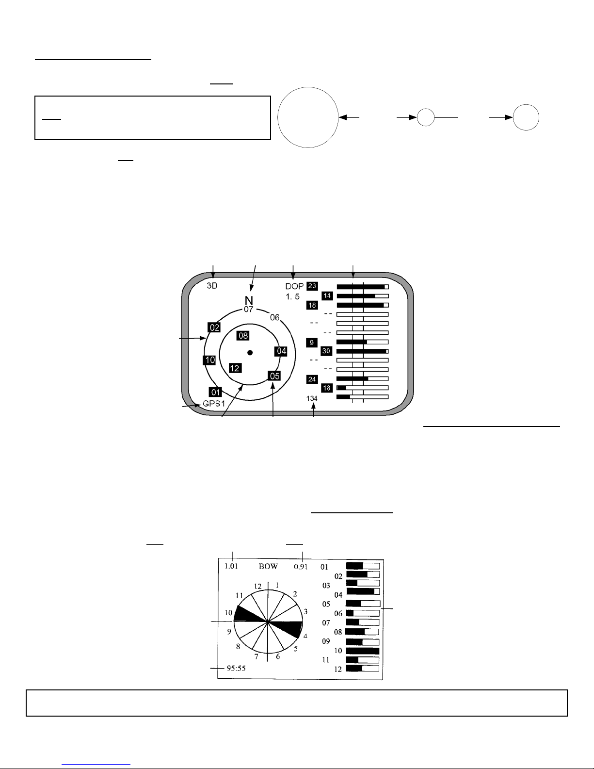
Position status North DOP RX signal level
lower is better
Bars that extend past first vertical line
are used in the headin
calculation
Elevation 5 °
(More accurate)
Antenna element no.
Troubleshooting: No RX signal on antenna 1, 2, or 3.
Switch antenna cable with one of the other known good
antennas to confirm antenna or processor problem
Elevation 45 °
(Less accurate)
Satellites
highlighted in
black used for
calculation
W
AS
Checking Installation- multi-path and receive problems (re-confirm after adding any new near-by structures on the vessel)
Maintenance Menu Access - Press and hold [MENU] and [ENT] keys simultaneously (~ 8 sec.), at third beep release
[MENU] key first, then [ENT] key. Access [ANT MONI] from the maintenance menu and press [ENT].
Multipath Index for the baseline
between antenna 1 and antenna 3
Must be 1.5 or lower
Multipath Index for the baseline
between antenna 1 and antenna 2
Must be 1.5 or lower
Circular Graph displays (in 12 directions) tracking
error in relation to the vessel bow. The highest error
and its opposing direction are shown in black
(illustration shows error at 10 and 4 o’clock
position). Note: Two (2) sectors will always be
illuminated even when no heading loss is present
Bar Graph displays tracking error in 12 directions
Longer bars = more error (caused by obstacles)
Sectors opposite to obstacle may have most error
Elapsed time displays accumulated tracking data
(up to 99 hrs 59 mins). Collect a minimum 12 hrs
of data for valid information.
After confirming above information, turn the vessel in a complete circle to check for correct and stable heading


