Furuno PP-505-FE User manual

PRINTER
PP-505-FE
OPERATOR'S MANUAL
www.furuno.com
Model
(For FE-700/FE-800)


i
IMPORTANT NOTICES
General
• The operator of this equipment must read and follow the descriptions in this manual. Wrong op-
eration or maintenance can cancel the warranty or cause injury.
• Do not copy any part of this manual without written permission from FURUNO.
• If this manual is lost or worn, contact your dealer about replacement.
• The contents of this manual and equipment specifications can change without notice.
• The example screens (or illustrations) shown in this manual can be different from the screens
you see on your display. The screens you see depend on your system configuration and equip-
ment settings.
• Save this manual for future reference.
• Any modification of the equipment (including software) by persons not authorized by FURUNO
will cancel the warranty.
• All brand and product names are trademarks, registered trademarks or service marks of their
respective holders.
How to discard this product
Discard this product according to local regulations for the disposal of industrial waste. For disposal
in the USA, see the homepage of the Electronics Industries Alliance (http://www.eiae.org/) for the
correct method of disposal.
How to discard a used battery
Some FURUNO products have a battery(ies). To see if your product has a battery(ies), see the
chapter on Maintenance. Follow the instructions below if a battery(ies) is used.
In the European Union
The crossed-out trash can symbol indicates that all types of batteries
must not be discarded in standard trash, or at a trash site. Take the
used batteries to a battery collection site according to your national
legislation and the Batteries Directive 2006/66/EU.
In the USA
The Mobius loop symbol (three chasing arrows) indicates that Ni-Cd
and lead-acid rechargeable batteries must be recycled. Take the used
batteries to a battery collection site according to local laws.
In the other countries
There are no international standards for the battery recycle symbol. The number of symbols can
increase when the other countries make their own recycle symbols in the future.
Cd
Ni-Cd Pb

ii
SAFETY INSTRUCTION
WARNING
WARNING
Do not open the cover of
the equipment.
This equipment uses high
voltage electricity which can
shock or burn.
Only qualified personnel
should work inside the
equipment.
Do not disassemble or modify the
equipment.
Fire, electrical shock or serious injury can
result.
Immediately turn off the power at the
ship's mains switchboard if water or
foreign object falls into the equipment
or the equipment is emitting smoke or
fire.
Continued use of the equipment can cause
fire, electrical shock or serious injury.
Do not operate the unit with wet hands.
Electrical shock can result.
Use the correct fuse.
Use of the wrong fuse can cause fire or
damage the equipment.
WARNING
WARNING
ELECTRICAL SHOCK HAZARD
Only qualified personnel
should work inside the
equipment.
This equipment uses high
voltage electricity which can
shock or burn.
Turn off the power at the ship's mains
switchboard before beginning the
installation. Post a warning sign near
the switchboard to ensure that the
power will not be applied while the
equipment is being installed.
Serious injury can result if the power is
not turned off, or is applied while the
equipment is being installed.
CAUTION
CAUTION
Observe the following compass safe
distances to prevent interference to a
magnetic compass:
CAUTION
CAUTION
PP-505 1.1 m 0.8 m
standard
compass
steering
compass
Safety Information for Operator Safety Information for Installer
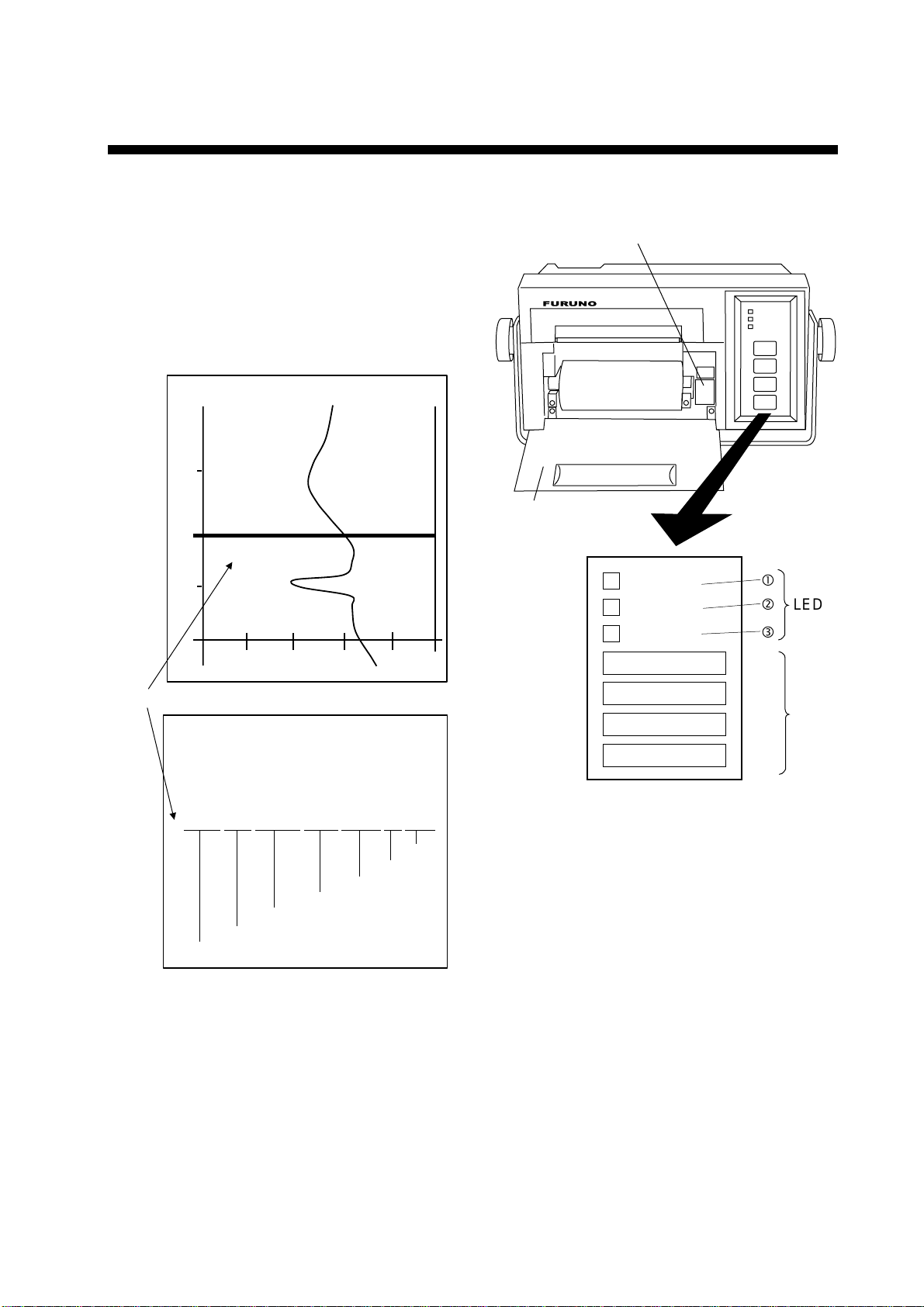
A warning label is attached
to the printer. Do not remove
the label. If the label is missing
or damaged, contact your dealer
about replacement.
WARNING
To avoid electrical shock, do not
remove cover. No user-serviceable
parts inside.
Name: Warning Label (1)
Type: 86-003-1011
Code No.: 100-236-231
WARNING LABEL
WARNING
Indicates a condition that can cause death or serious
injury if not avoided.
CAUTION
Indicates a condition that can cause minor or moderate
injury if not avoided.
Warning, Caution Mandatory Action
Prohibitive Action
Read these safety instructions before you operate the equipment.

iii
FOREWORD
A Word to the Owner of the PP-505
Congratulations on your choice of the FURUNO PP-505 Printer.
For 60 years FURUNO Electric Company has enjoyed an enviable reputation for innovative and
dependable marine electronics equipment. This dedication to excellence is furthered by our
extensive global network of agents and dealers.
Your printer is designed and constructed to meet the rigorous demands of the marine
environment. However, no machine can perform its intended function unless installed, operated
and maintained properly. Please carefully read and follow the recommended procedures for
installation, operation and maintenance.
We would appreciate hearing from you, the end-user, about whether we are achieving our
purposes.
Thank you for considering and purchasing FURUNO equipment.
The PP-505 prints a depth graph or a log consisting of date, time, depth, draft, latitude,
longitude and heading.
You can choose which to print with the [MODE] key.
The main features are
• Automatic operation; just turn on the power and the printer readies itself for printing.
• Selectable printing interval.
• LEDs show equipment status.

i
v
TABLE OF CONTENTS
1. OPERATION..................................................................................................... 1
1.1 General .........................................................................................................................1
1.2 Panel.............................................................................................................................1
1.3 Turning on the Power ....................................................................................................2
2. REPLACEMENT OF THERMAL PAPER......................................................... 3
3. INSTALLATION ................................................................................................ 4
3.1 Complete Set ................................................................................................................4
3.2 General Mounting Considerations .................................................................................4
3.3 Tabletop/Bulkhead Mount ..............................................................................................5
3.4 Flush Mount ..................................................................................................................5
3.5 Wiring............................................................................................................................6
4. MAINTENANCE ............................................................................................... 7
APPENDIX
REPLACEMENT OF PRINTER ASSEMBLY/THERMAL HEAD
........ AP-1
SPECIFICATIONS........................................................................................... SP-1
PACKING LIST.................................................................................................. A-1
OUTLINE DRAWING......................................................................................... D-1
INTERCONNECTION DIAGRAM ......................................................................S-1

1
1. OPERATION
1.1 General
Operation of the PP-505 is simple; just turn
on the power. The depth graph or the log,
whichever is selected for printing, is printed
out at the interval set.
Below are example printouts.
60m 80m 100m20m 40m
Marker
2003/12/01 13:05:00 038.6m/01.0m 35 20.02’N/135 45.15’E 15.1kt 008.0deg
M
Date Time Depth,
Draft
Latitude
Longitude
Heading
Speed
Depth graph
Depth data log
2003/12/01 13:05:00 038.6m/01.0m 35 20.02’N/135 45.15’E 15.1kt 008.0deg
M
13:05:00
1.2 Panel
PRINTER
PP-505
POWER
ON
GRAPH
LOG
PAPER
MODE
INTERVAL
RANGE
FEED/MARK
Power Switch
Thermal Paper
Cover
GRAPH
MODE
INTERVAL
RANGE
FEED/MARK
LOG
PAPER
LED
Key
Indicators
There are three (red) LEDs on the front
panel which light or blink according to
equipment status.
!GRAPH
Lights while the depth graph is being
printed.
"LOG
Lights while the depth data log is being
printed.
#PAPER
Blinks when the paper has run out, and is
accompanied by the audible alarm. The
audible alarm sounds for five seconds; you
may silence it sooner by hitting any key.

OPERATION
2
Changing the mode
Press the [MODE] key to change the printing
mode from depth graph to log printing
alternately.
The printing interval setting is printed
whenever the [MODE] key is pressed.
Changing the printing interval
Press the [INTERVAL] key to choose printing
interval.
Depth graph: 9 s →45 s →90 s →450 s
Log: 10 s →30 s →1 m →10 m
The latest data of the printing interval is
printed.
When the printing interval is changed, the
printing interval setting is printed and marked
with an asterisk.
Note: You can skip over setting(s) by
pressing the key consecutively within
one second.
Changing the depth range
Press the [RANGE] key to change the depth
range.
When the depth range is changed, the depth
is printed and marked with an asterisk.
Range: 5 m →10 m →20 m →40 m →
100 m →200 m →400 m→800 m
Note1: Depth range automatically changes
depending on the depth range on the
navigational echo sounder.
Note2: You can skip over setting(s) by
pressing the key consecutively within
one second.
Feeding the paper/Printing the marker
To feed the paper, press and hold down the
[FEED/MARK] key.
Press the [FEED/MARK] key momentarily to
print the marker.
1.3 Turning on the Power
Flip down the thermal paper cover and turn
on the [POWER] switch. The PP-505 then
carries out the diagnostic test. After the test
has been completed, the printer is ready to
print depth data.
Note: “Disconnect” is printed if data from the
navigation echo sounder is not being
received during printing or the
navigation echo sounder is displaying
the system menu.
To turn off the power, press the [POWER]
switch.

3
2. REPLACEMENT OF THERMAL
PAPER
When the thermal paper runs out, the PAPER
LED blinks, printing stops automatically and the
aural alarm sounds for five seconds.
With 1 meter of paper remaining, a red paper
end mark appears on the paper. When the red
mark appears, replace the thermal paper as
shown in the procedure below.
1. Press the [FEED/MARK] key to draw out the
remaining thermal paper.
2. Pull the thermal paper cover forward and
take out the paper spool.
3. Curve the leading edge of the new roll paper
to ensure smooth feeding, and set the paper
spool to the new roll paper.
4. Insert the paper into the paper insertion slot
just above the paper container and press the
[FEED/MARK] key to feed out the paper.
5. Set the paper in the paper container.
6. Press the [FEED/MARK] key to confirm that
the paper is properly aligned.
If the paper comes out with its edges wrin-
kled, continue to press the [FEED/MARK]
key. Correct alignment will be made automat-
ically.
7. Close the thermal paper cover.
8. Press the [MODE] key to complete the
replacement of thermal paper. (The PAPER
LED goes off.)
Note: If the PP-505 receives data when there is
no paper it doesn't print them out after replacing
the thermal paper.
Remedy for paper jam
If the paper is jammed cut it off at the front panel
and rewind it into the paper container by hands.
REQUIRED THERMAL PAPER
Type: TP0340 (112 mmx40 m)
Code No.: 000-801-765
Be sure to use the specified
thermal paper.
RED mark
Reel
Thermal paper cover
Tape
Adhesive may
remain on paper
after tape is removed.
This may cause a
paper jam, so cut
paper to remove
adhesive.
Adhesive
Confirm that paper
is fed out
through the slot. Insertion slot

4
3. INSTALLATION
3.1 Complete Set
Name Type Mass Qty Remark
Main Unit PP-505 3.1 kg
(with hanger) 1
Spare Parts SP08-01600 1
Installation
Materials CP16-00800 1
Accessories FP08-00500 1
Flush Mount Kit OP08-4 1 Option (004-511-330)
3.2 General Mounting
Considerations
This equipment can perform its intended
functions only if it is installed properly. Keep
in mind the following when selecting a
mounting location.
Water spray
The PP-505 is designed and constructed to
be able to withstand the humidity and
corrosive atmosphere common to the
pilothouse, but it is not designed to be used
outside, directly exposed to the environment.
Salt water spray will most assuredly cause
damage to the sensitive components inside.
Mechanical shock and vibration
The PP-505 is constructed to withstand minor
shocks and engine vibration, but excessive
and continued shock can shorten the life of
the precision printer mechanism. Shock may
also degrade the print quality due to uneven
contact between the printer head and the
thermal paper.
Heat accumulation
The PP-505 consumes very little power, so
there is no need for forced air ventilation.
However, it is recommended to provide at
least some space around the unit to allow for
circulation of cooling air.
The unit should be kept out of direct sunlight
because of heat that can build up inside the
cabinet. Excessive heat can darken the
thermal paper.
Onboard noise
To avoid mutual interference with other power
equipment, do not install this unit near a
power cable or equipment having a motor.
Compass safe distance
A magnetic compass will be affected if the
printer is placed too close to the compass.
Observe the following compass safe
distances to prevent deviation to the
compass.
Standard: 1.1 m
Steering: 0.8 m

5
3.3
Tabletop/Bulkhead Mount
3.4 Flush Mount
The main unit can be mounted on a desktop,
bulkhead, or in a panel. Make sure the
selected location is strong enough to support
the main unit against possible vibration and
shock. If necessary, appropriate
reinforcement measures should be made on
the mounting area.
Tabletop mount
1. Drill four pilot holes for the hanger.
2. Fix the hanger with the tapping screws
(5×20) supplied.
3. Place the unit in the hanger and tighten
knobs.
268
2.9 kg
107
141
Knob bolt
Hanger washer
0.2
Tapping screw
Flat washer
Hanger
90
60
120
200
480
Bulkhead mount
When the unit is installed on the bulkhead,
fix the hanger as shown below.
Flush mount panel kit is optionally supplied.
Flush mount kit OP08-4 (Code No.:
004-511-330)
Name Type Code No.
Qty.
Flush
mount
panel
22-008-0125 100-103-351 1
Ta p p in g
screw
5x20 000-163-867-10 4
Nylon
washer
2.8x7x0.5 000-800-728 4
Pan
head
screw
M3x8 000-163-669-10 4
Hex.
bolt
M8x16 000-162-291-10 2
Flat
washer
M5 000-864-128 4
Flat
washer
M8 000-864-130 2
Spring
washer
M8 000-864-262 2
Rosette
washer
M3 000-864-900 4
Flush
mount
angle
22-008-0126 100-103-361-10 2
Liner 22-008-0127 100-103-371 2

3. INSTALLATION
6
1. Referring to the illustration below, prepare
a cutout in the mounting area and drill four
pilot holes for the flush mount angles.
Refer to the outline drawing at end of manual.
2. Fix the liner and the flush mount angles to
the main unit.
3. Connect the cables at the rear of main
unit.
4. Fix the main unit to the panel cutout with
four tapping screws.
5. Fix the flush mount panel to the flush
mount angles with the screws and
washers supplied.
Tapping screws Pan head screw
Flat washer
Nylon washer
Rosette washer
Flush mount
panel
Flush mount angle
Flat
washer
Spring
washer
Hex. bolt
295
280 156
7
10
Liner
116
3.5 Wiring
Refer to the interconnection diagram at end
of manual for connection.

7
4. MAINTENANCE
Checking the power connector
Check for loosened or disconnected power
connector.
WARNING
Do not open the cover of
the equipment.
This equipment uses high
voltage electricity which
can shock or burn.
Only qualified personnel
should work inside the
equipment.
Do not disassemble or modify the
equipment.
Fire, electrical shock or serious injury
can result.
Diagnostic test
When turning on the power, if any fault is
detected, the appropriate LED lights.
GRAPH: ROM error
LOG: RAM1 error
PAPER: RAM2 error
If any LEDs light, contact your dealer.
Cleaning
Accumulated dust should be regularly
removed from both exterior surfaces and the
interior. The only recommended cleaning
material for exterior surfaces is a soft cloth.
For the interior, use a handheld vacuum. BE
SURE TO TURN OFF THE POWER
BEFORE CLEANING THE INSIDE OF THE
UNIT. Do not use chemical-based cleaners to
clean the display unit-they can remove paint
and markings.
Fuse Replacement
To protect the equipment from serious
damage, a 3A fuse is provided on the rear
cabinet of the main unit. The fuse protects
against overvoltage/reverse polarity of the
ship’s mains or internal fault of the equipment.
If the fuse has blown, first find out the cause
of the trouble before replacing it. A fuse rated
for more than 3 A should not be used, since it
may permanently damage the equipment.
Damage due to overfusing is not covered by
the warranty.
CAUTION
Use the correct fuse.
Use of the wrong fuse can cause fire
or damage the equipment.

A
P-1
APPENDIX REPLACEMENT OF
PRINTER ASSEMBLY/TERMAL HEAD
1. Loosen the four M4 × 15 screws fixing the
rear cabinet to the main unit assembly.
2. Disconnect the connectors connected to
the rear cabinet to detach the rear
cabinet.
Rear
Cabinet
Main Unit Assembly
P1
NH
4P P5
NH
6P M4 ×15
screw
(4 pcs.)
3. Separate the panel assembly from the
main unit assembly by removing the
recording paper from the paper container.
Main Unit
Assembly Printer
Assembly
PANEL CPU Board
Do not
Disconnect.
Panel
Assembly
P4
PH
12P P8
PH
10P
P10
PH12P
M4 × 8
screw
(4 pcs.)
4. Move the carriage to position
A
by
rotating the carriage shaft by fingers, as
shown below, where the thermal head
assembly can be replaced easily.
Carriage Shaft Carriage
A
5. Remove the flexible cable support from
the carriage by lifting it toward direction
B
as in the figure below.
Flexible Cable Support
Carriage

A
P-2
6. Pull out the connector end of the flexible
cable from the connector. Take care not to
damage the flexible cable.
End of Flexible
Cable (Connector) 180°
7. Remove the thermal head from the head
holder with a screwdriver as shown below,
and then take the thermal head assembly
out of the printer assembly.
Thermal Head
Head Holder
Screwdriver
8. As shown below, pass the flexible cable
(connector side) of a new thermal head
assembly beneath the guide pins.
End of Flexible
Cable
Guide Pin
9. Hold the flexible cable end with a
tweezers and pull it out until it is
positioned as shown below.
Thermal
Head
Head Holder
90°
10.Turn the head by 90° so that it is parallel
with the head holder as shown below.
While pulling the head holder toward you,
insert the head into the head holder.
Head Holder
Flexible Cable
Head
Hole
Projection
Carriage

A
P-3
11. Fix the flexible cable to the carriage with
the flexible cable support, inserting the
projection on the carriage into the hole of
the cable.
Flexible Cable Support
Carriage
Projection
12.Fold back the end of the cable and insert
it into the connector.
End of Flexible
Cable
180°

FURUNO
PP-505-FE
SP - 1 E2366S02B
SPECIFICATIONS OF PRINTER
PP-505-FE (PRINTER FOR FE-700/800)
1 DATA FORMAT
1.1 Receiving system RS-232C
1.2 Speed 9600 bps
1.3 Data length 8 bits
1.4 Parity Non
1.5 Stop bit 1 bit
2 PRINTER SECTION
2.1 Printing system 9 dots serial thermal head printing system
2.2 Character Alphanumeric
2.3 Dot pitch 0.28 mm/ dot
2.4 Number of dot in line 300 dots
2.5 Number of characters Max. 80 characters/ line
2.6 Print speed 31 cps
2.7 Roll paper TP-0340, 112 mm (W) x 40 m (L)
3 POWER SUPPLY
12-24 VDC, 15 W max. (receiving), 9 W (stand-by)
4 ENVIRONMENTAL CONDITION
4.1 Ambient temperature -15°C to +55°C
4.2 Relative humidity 95% at 40°C
4.3 Waterproofing IPX0
4.4 Bearing vibration IEC 60945
5 COATING COLOR
Chassis: 2.5GY5/1.5, Panel: N3.0

㧼㧭㧯㧷㧵㧺㧳ޓ㧸㧵㧿㨀
#':
22('
0#/' 176.+0' &'5%4+26+10%1&'ͳ 36;
࡙࠾࠶࠻ 70+6
㩖㩩㩢㩧㩊㨺
24+06'4
22('
ຠ 52#4'2#465 52
⸥㍳⚕ᗵᾲ
4'%14&+0)2#2'46*'4/#.
62//:/
ຠ
52#4'2#465
52
ઃዻຠ #%%'5514+'5 (2
㩓㩖㩨㩘㩨㩣㩎
*#0)'4(+:+0)5%4'9-+6
(2
㩔㩧㩀㩨㨺⚵ຠ
*#0)'4#55;
(2
Ꮏ᧚ᢱ +056#..#6+10/#6'4+#.5 %2
㩃㨺㩖㩨㩣⚵ຠ
219'4%#$.'#55;
5
5
㩄㩒㩂㩊
%100'%614
%2
࿑ᦠ &1%7/'06
ขᛒ⺑ᦠ⧷
12'4#6145/#07#.
1/'
ขᛒ⺑ᦠ㧕
12'4#6145/#07#.
1/,
䋨⇛࿑䈱ኸᴺ䈲䇮ෳ⠨୯䈪䈜䇯㩷㩷㪛㪠㪤㪜㪥㪪㪠㪦㪥㪪㩷㪠㪥㩷㪛㪩㪘㪮㪠㪥㪞㩷㪝㪦㪩㩷㪩㪜㪝㪜㪩㪜㪥㪚㪜㩷㪦㪥㪣㪰㪅䋩
ဳᑼ㪆䍘䍎䍢䍼⇟ภ䈏䋲Ბ䈱႐ว䇮Ბ䉋䉍Ბ䈮ઍ䉒䉎ㆊᦼຠ䈪䈅䉍䇮䈬䈤䉌䈎䈏䈦䈩䈇䉁䈜䇯䇭䈭䈍䇮ຠ⾰䈲ᄌ䉒䉍䉁䈞䉖䇯
㪫㪮㪦㩷㪫㪰㪧㪜㪪㩷㪘㪥㪛㩷㪚㪦㪛㪜㪪㩷㪤㪘㪰㩷㪙㪜㩷㪣㪠㪪㪫㪜㪛㩷㪝㪦㪩㩷㪘㪥㩷㪠㪫㪜㪤㪅㩷㩷㪫㪟㪜㩷㪣㪦㪮㪜㪩㩷㪧㪩㪦㪛㪬㪚㪫㩷㪤㪘㪰㩷㪙㪜㩷㪪㪟㪠㪧㪧㪜㪛㩷㪠㪥㩷㪧㪣㪘㪚㪜㩷㪦㪝㩷㪫㪟㪜㩷㪬㪧㪧㪜㪩㩷
㪧㪩㪦㪛㪬㪚㪫㪅㩷㪨㪬㪘㪣㪠㪫㪰㩷㪠㪪㩷㪫㪟㪜㩷㪪㪘㪤㪜㪅
%<%
A
-1
%1&'01
6;2'
%2
⇛ޓޓ࿑
176.+0'
ฬޓޓ⒓
0#/'
ᢙ㊂
36;
↪ㅜ㧛⠨
4'/#4-5
⇟ภ
01
ဳฬ㧛ⷙᩰ
&'5%4+26+105
+056#..#6+10/#6'4+#.5
Ꮏ᧚ᢱ
#':
22
㨻㨺㩇✢
)4170&+0)9+4' 5
%1&'01
㩄㩒㩂㩊(/
%100'%614 (/2
%1&'01
㩄㩒㩂㩊㧔:/
%100'%614&57$ :/55
%1&'01
㧔⇛࿑ߩኸᴺߪޔෳ⠨୯ߢߔޕޓ&+/'05+105+0&4#9+0)(144'('4'0%'10.;㧕
㧲㨁㧾㨁㧺㧻ޓ㧱㧸㧱㧯㨀㧾㧵㧯ޓ㧯㧻ޓ㧚㧘㧸㨀㧰
ဳᑼ㩄㨺㩎㩨⇟ภ߇㧞Ბߩ႐วޔᲑࠃࠅᲑߦઍࠊࠆㆊᦼຠߢࠅޔߤߜࠄ߆߇ߞߡ߹ߔޕޓߥ߅ޔຠ⾰ߪᄌࠊࠅ߹ߖࠎޕ
6916;2'5#0&%1&'5/#;$'.+56'&(14#0+6'/6*'.19'4241&7%6/#;$'5*+22'&+02.#%'1(6*'722'4241&7%6
37#.+6;+56*'5#/'
%/'
A
-2

%1&'01
6;2'
(2
⇛ޓޓ࿑
176.+0'
ฬޓޓ⒓
0#/'
ᢙ㊂
36;
↪ㅜ㧛⠨
4'/#4-5
⇟ภ
01
ဳฬ㧛ⷙᩰ
&'5%4+26+105
#%%'5514+'5
ઃዻຠ
#5:
㩔㩧㩀㩨㨺㩦㨹㩆㨶㨺
*#0)'49#5*'4
%1&'
01
41*5
㩏㩗㩨㩊㨹㩕㩩㩧7+㩆㨷
5'.(6#22+0)5%4'9 :575
%1&'
01
㩓㩖㩨㩘㩨㩣㩎
-01$$1.6 -)$/:575
%1&'
01
㩚㩀㩨㩁ᐔᐳ㊄
(.#69#5*'4 /575
%1&'
01
㧔⇛࿑ߩኸᴺߪޔෳ⠨୯ߢߔޕޓ&+/'05+105+0&4#9+0)(144'('4'0%'10.;㧕
㧲㨁㧾㨁㧺㧻ޓ㧱㧸㧱㧯㨀㧾㧵㧯ޓ㧯㧻ޓ㧚㧘㧸㨀㧰
ဳᑼ㩄㨺㩎㩨⇟ภ߇㧞Ბߩ႐วޔᲑࠃࠅᲑߦઍࠊࠆㆊᦼຠߢࠅޔߤߜࠄ߆߇ߞߡ߹ߔޕޓߥ߅ޔຠ⾰ߪᄌࠊࠅ߹ߖ
ࠎޕ
6916;2'5#0&%1&'5/#;$'.+56'&(14#0+6'/6*'.19'4241&7%6/#;$'5*+22'&+02.#%'1(6*'722'4
241&7%637#.+6;+56*'5#/'
%(%
A
-3
%1&'01
6;2'
52
+6'/
01
0#/'1(
2#46 176.+0'
&9)01
14
2'4
5'6
2'4
8'5
52#4'
914-+0)
37#06+6; 4'/#4-5%1&'01
$1:012
5*+201
52#4'2#465.+56(14 75'
5'652'4
8'55'.
6;2'01
#5:
㩕㨷㨺㩇㩨
()/$8#
2$(
(75').#55
67$'6;2'
/(450#/'
(74701'.'%64+%%1.6&
&9)01
㧔⇛࿑ߩኸᴺߪޔෳ⠨୯ߢߔޕޓ&+/'05+105+0&4#9+0)ޓ(144'('4'0%'10.;㧕
%2'
ဳᑼ㩄㨺㩎㩨⇟ภ߇㧞Ბߩ႐วޔᲑࠃࠅᲑߦઍࠊࠆㆊᦼຠߢࠅޔߤߜࠄ߆߇ߞߡ߹ߔޕޓߥ߅ޔຠ
⾰ߪᄌࠊࠅ߹ߖࠎޕ
6916;2'5#0&%1&'5/#;$'.+56'&(14#0+6'/6*'.19'4241&7%6/#;$'5*+22'&+02.#%'1(
6*'722'4241&7%637#.+6;+56*'5#/'
A
-4

Dec.08 '03
D-1
Table of contents
Other Furuno Printer manuals