CONTENTS
SYSTEM CONFIGURATION................................................................................1
1. FUNCTION OF EACH UNIT
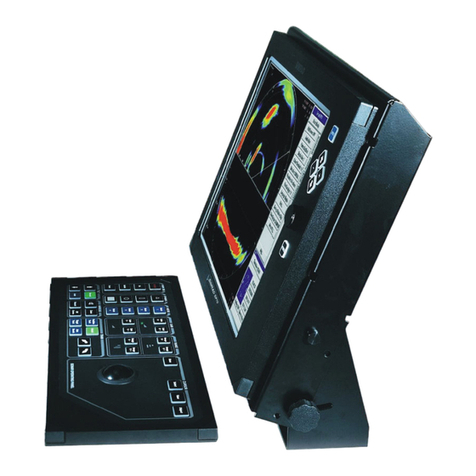
1.1 Display Unit (MU-100C)..................................................................................3
1.2 Control Unit (CH-252)......................................................................................4
1.3 Transceiver Unit (CH-273) ...............................................................................5
1.3.1 CPU Board (06P0258)............................................................................5
1.3.2 TRX Board (06P0241) ...........................................................................6
1.3.3 PWR Board (06P0242)...........................................................................7
1.3.4 PRA Board (06P0259)............................................................................8
2. FUNCTIONAL DESCRIPTION
2.1 Transmission.....................................................................................................9
2.2 Reception..........................................................................................................9
2.3 Raising/Lowering Transducer.........................................................................12
2.4 Tilting Transducer...........................................................................................13
2.5 Training Transducer........................................................................................15
2.6 Braking Tilt/Train Motor ................................................................................17
3. CHECK AND ADJUSTMENT
3.1 Test Points.......................................................................................................18
3.2 LED Indication................................................................................................21
3.3 Adjustment......................................................................................................22
4. PARTS LOCATION
4.1 Display Unit....................................................................................................24
4.2 Control Unit....................................................................................................26
4.3 Transceiver Unit..............................................................................................26
5. MAINTENANCE
5.1 Replacement of Grease Cotton .......................................................................32
5.2 Soundome (D) Replacement...........................................................................32
5.3 Transducer Replacement.................................................................................34
5.4 Tilt Gear Box Replacement.............................................................................35
5.5 Slip Ring Replacement....................................................................................36
5.6 Carbon Brush Replacement ............................................................................37
5.7 Tilt Code Disk Alignment...............................................................................38
6. TROUBLESHOOTING
6.1 Flow Chart ......................................................................................................40
Appendix A CH-250 vs CH-270..............................................................................46
Mechanical Parts List ................................................................................... 48
Exploded view .............................................................................................D-1
Schematic Diagram .......................................................................................S-1


