manuals.online logo
Brands
  1. Home
  2. •
  3. Brands
  4. •
  5. FUTABA
  6. •
  7. Receiver
  8. •
  9. FUTABA R6303SB User manual

FUTABA R6303SB User manual

Usage condition for conventional system output
(Ch1-3) on "High Speed mode"
󾾝CAUTION
󾾙The "High Speed mode" accept the digital servos only or
most type of peripherals.
•Ifananalogservoisconnectedtotheseoutputsitwillcausea
malfunction.Pleasechecktheperipheralsifthereisamalfunctionfull
stickmovement.Ifthereisamalfunctionchangethereceiverbackto
"Normal mode."
Applicable systems: FASST-2.4GHz 7ch or 8ch/10ch/Multi-ch system
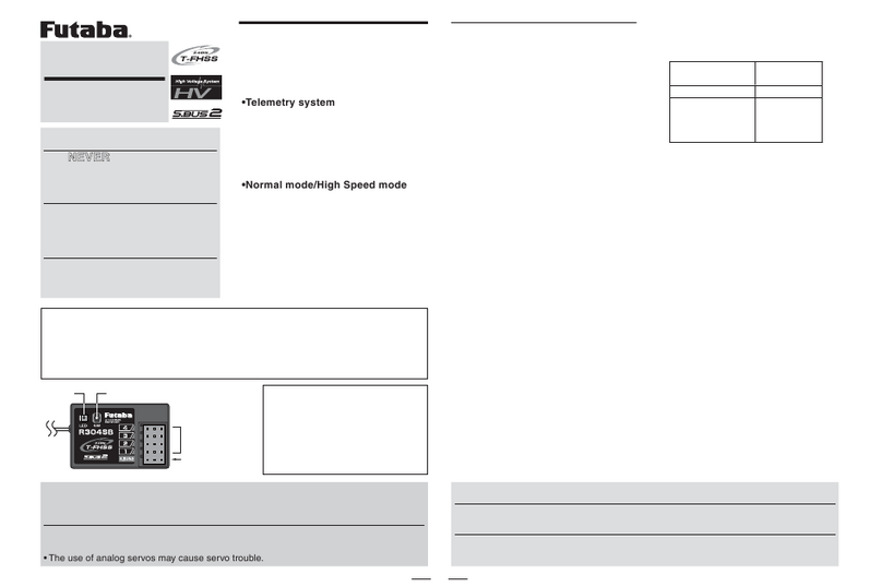
R6303SB FASST-2.4GHz (7ch/8ch/10ch/Multi-ch) system
S.BUS port and 3 channels for conventional system
High-Speed receiver
Compliance Information Statement
(for U.S.A.)
This device, trade name Futaba Corporation of America, model number R6303SB,
complies with part15 of the FCC Rules. Operation is subject to the following two
conditions:
(1) This device may not cause harmful interference, and
(2) This device must accept any interference received, including interference that may
cause undesiredoperation.
The responsible party of this device compliance is:
Futaba Service Center
3002 N Apollo Drive Suite 1, Champaign, IL 61822 U.S.A.
TEL (217)398-8970 or E-mail: [email protected] (Support)
R6303SB Specications
FASST-2.4GHz (7ch/8ch/10ch/Multi-ch) system/S.BUS port and 3 channels for
conventional system/high-speed receiver
• Dual antenna diversity
• Size: 0.89 x 1.47 x 0.37 in. (22.5 x 37.4 x 9.3 mm)
• Weight: 0.25 oz. (7.2g)
• Power requirement: 3.7V to 7.4V(Voltage range: 3.5 to 8.4V)
* Be sure that when using ESC's regulated output the capacity of the ESC must meet your usage
condition.
*The Battery F/S voltage is set for 4-cell NiCd/NiMH battery. Battery F/S function doesn't
work properly when other type battery is used.
* The fail safe function can be set for each channel when on "Multi-ch" mode, however, it differs
according to the transmitter. When on "7ch" mode, the fail safe function can be set for 3-channel
only.
*S.BUS port: R6303SB can be used up to 7 channels or less on the "7ch" mode and 16 channels +
DG1/2 or less on the "8ch/10ch/Multi-ch" mode, however, it differs according to the transmitter.
Thank you for purchasing a Futaba R6303SB FASST-2.4GHz receiver.
The R6303SB has an S.BUS system output port and 3 conventional
system channel outputs. It can also be used with conventional system
servos, etc. in addition to S.BUS system compatible servos and gyros,
etc. When the linking procedure is performed, R6303SB recognizes the
signal mode (FASST-2.4GHz 7ch mode or 8ch/10ch/Multi-ch mode)
automatically.
The R6303SB can change the output CH from seven groups (CH group
table).
In addition, the operating mode (high-speed mode/normal mode) can be
selected.
󾾝WARNING
󾾛DonotperformtheLinkingprocedurewiththe
motorpoweredup.Thiscouldresultinserious
injury.
󾾙OncetheLinkingprocessiscompletedplease
cyclethepowertothereceivertomakesurethat
itislinkedandunderthecontroloftheTransmitter.
Link to the Transmitter
1PressandholdtheLink/Modebuttonbetween2and5
seconds.
Re-adjust the 3CH F/S position (only for TM-8)
1PressandholdtheLink/Modebuttonbetween1and2
seconds.
0 to 1 sec. 1 to 2 sec. 2 to 5 sec. More than 5 sec.
0 sec. 1 sec. 2 sec.
Press and Hold
No function
With TM-8
(not included in this set)
To set the F/S
position(No re-link)
Re-link(ID set) and to
set the F/S position
No function
Other than TM-8
(not included in this set)
Re-link(ID set)
CH change mode
CH change mode
5 sec.
Power Source Precautions
It is not recommended to use a power source of less then 4.0V.
However if less than 4.0V is used please keep in mind the conditions
below..
•The FailSafeFunctionMUSTbe set to"OFF"since itwilldisturb the
normal operation of the receiver.
•Please makesure that the fully loaded conditionontheESCand the
Servos will not disturb normal receiver operation before the start of
youright.
 This isVERY Important once the voltage drops below 3.5 volts the
receiverwillnolongercontinuetooperate.
•Please be sure that everything on continues to work correctly all the
waydownto3.5volts.ie:Servos,ESC...
The input voltage must not exceed the servo rating or 8.4V which ever
is lower.
Antenna installation precaution
󾾝WARNING
󾾙Besurethatthetwoantennasareplacedat90degreesto
each other.
•Futaba's dual antenna diversity, or DAD, then seamlessly selects the
best signal reception between these antennas to ensure that there is
no loss of signal.
Antenna installation for carbon fuse
󾾝WARNING
󾾙Thelast30mmoftheantennatipmustbefullyexposed.
•Please makesure thatthe exposedportion will notbe ableto
slidebackinsidetheaircraftbyanyforcesduringight.
(Antenna installation)
90˚
Link/Mode button
LED
R6303SB
•Port2(InitialsettingistheChannel2)
•Port1(InitialsettingistheChannel1)
•Channel3outputforconventionalsystem/Battery
terminal
•S.BUSPort
(Connectors)
1M23N17462
Operation Normal/High Speed Mode Select
The operation mode is set on "Normal Mode" from the factory. To
change the mode please follow the steps below.
1Turnoffthereceiver.
2PressandholdtheLink/Modebuttonandturnonthereceiver.
Pressandhold the buttonformore then1second. TheLED
willstarttoashandwillindicatethecurrentstatus.
3Releasethebutton.
4Turnoffthereceiver.
By following these steps the receiver modes can be switched back and
forth between normal and high speed modes.
0 to 1 sec. More than 1 sec.
0 sec. 1 sec.
Press and Hold
Turn on the receiver.
No function
Showing the CURRENT
mode with blink.
Red Blink = Normal
Green/Red Blink =
High Speed
Solid as the mode changed.
Red Solid = Normal
Green/Red Solid = High
Speed
(Become Red after
1second)
(Function)To change the mode between
Normal and High Speed
(LED
Status)
Please check the operation mode by observing the LED when turning on
the receiver. The best way to conrm the mode you are on is to make sure
that there are no other
FASST
transmitters turned on around you.
When turning on the receiver, the LED will be;
•Redwhenon"Normalmode"
•GreenandRed(makingorange)whenon"HighSpeedmode". (After2
seconds,theLEDwillchangetored.)
If there are any FASST transmitters turned on around the receiver, the
LED may show the above status, but just for a brief moment and then
change to the status indicated in the "LED indication" table below.
How to Set the Operation Channel
It is possible to choose the operation channel mode of the port 1 and 2
from 7 setting groups.
1Turn onthe receiver.  (At this moment, the transmittershould
beoff.)Then, ensure theLEDis lit inRED or ashinggreen
light.
2PressandholdtheLink/Modebuttonmorethan5seconds.
3Releasethebutton whentheLEDblinksREDandGREEN
simultaneously.
4Thereceiverisnowinthe "OperationCHSet" mode. At this
moment,theLEDindicatescurrentsetstatusthroughashing
apatternthatcorrespondstotheCHgroup.
*Cannot exit this CH setting mode before the operation mode is xed.
**See the below table that shows correspondence between "CH group" and way
of ashing LED.
***Default CH mode is "Group 1".
5By pressing the Link/Modebutton,theoperationCHisswitched
sequentiallyas"group1""group2""group3"....
6Theoperation modewillbesetby pressingtheLink/Mode
buttonmorethan2secondsatthedesiredCHgroup.
7Releasethebutton whentheLEDblinksREDandGREEN
simultaneously.Afterreleasingthebutton,theREDand
GREENLEDarelit1secondsimultaneously.Then,the
operationCHisxed.
8 After conrming the operation CH mode is changed, turn off
andbackonthereceiverpower.
*The “Operation CH Set” mode cannot be changed during the receiver
communicates to the transmitter.
FUTABA CORPORATION
1080 Yabutsuka, Chosei-mura, Chosei-gun, Chiba-ken, 299-4395, Japan
Phone: +81 475 32 6982, Facsimile: +81 475 32 6983
©FUTABA CORPORATION 2012, 4 (1)
LED Indication
Green Red Status
Solid Solid Initializingwhenon"HighSpeedmode"
Off Solid No signal reception
Solid Off Receivingsignals
Blink Off ReceivingsignalsbutIDisunmatched
Alternate blink Unrecoverableerror(EEPROM,etc.)
CH group table
CH group LED blink Port 1 Port 2
group 1 Red 1time CH1 CH2
group 2 Red 2time CH1 CH4
group 3 Red 3time CH2 CH4
group 4 Green 1time CH1 CH5
group 5 Green 2time CH2 CH7
group 6 Green 3time CH4 CH8
group 7 Red/Green 1time CH11 CH12
group 8 Red/Green 2time not used not used
group 9 Red/Green 3time not used not used
※Initial setting is group 1.
※The groups 8 and 9are not usually used.
※3CH port and S.BUS port never change.
R6303SB
[Example:ConnectingGYA431toGroup3]
(GYA431isusedfortheaileronofanairplane)
CH4
Rudderservo
CH6
2ndAileronservo
CH2
Elevatorservo
Port1
Port2
S.BUS
3/B CH1
Aileronservo
Battery CH3
Throttleservo
GYA431
HUB
When using the R6303SB Receiver with the
GYA430, 431 and CGY750
The following table corresponds to the gyro's functions. A port can be
used effectively. The servo which a gyro controls is connected to a gyro.
* Please refer to the description of each gyro manual.
S.BUS gyro group table
Gyro control CHCH group
Rudder group 1
Elevator group 2
Aileron group 3
Elevator+Rudder group 4
Aileron+Rudder group 5
Aileron+Elevator group 6
Aileron+Elevator+Rudder
or CGY750 group 7
When S.BUS is used
* Set the channel of S.BUSservosbyusinganSBC-1channelchanger,CIU-2
USBserialinterfaceortheprogrammingsoftwareinthe18MZ transmitter.
* Can also be used together with conventional servos. However, conventional
servos cannot be used by the S.BUS output.
* When using servos with a remote battery pack, use S.BUS Hub with Cable
(2-way/remote battery pack use).
Please refer to the instruction manual of S.BUS Hub with Cable (2-way/re-
mote battery pack use) for the connection method.
*Turn on the power in transmitter→receiver order. In addition, always check
the operation of all the servos before ight.
*Do not insert or remove the servo connector while the receiver power is ON.
What is S.BUS?
S.BUS is different from conventional radio control systems in that it
uses data communication to transmit control signals from the receiver
to a servo, gyro, or other S.BUS compatible devices. The S.BUS
devices only execute only those comands for there own set channel.
This is why a single signal can be used to connect multiple servos.
Other FUTABA Receiver manuals

FUTABA R314SB-E User manual

FUTABA

FUTABA R314SB-E User manual

FUTABA R404SBS-E User manual

FUTABA

FUTABA R404SBS-E User manual

FUTABA R7008SB User manual

FUTABA

FUTABA R7008SB User manual

FUTABA R304SB User manual

FUTABA

FUTABA R304SB User manual

FUTABA R404SBS-E User manual

FUTABA

FUTABA R404SBS-E User manual

FUTABA T-FHSS Air R3001SB User manual

FUTABA

FUTABA T-FHSS Air R3001SB User manual

FUTABA T10PX User manual

FUTABA

FUTABA T10PX User manual

FUTABA R7308SB User manual

FUTABA

FUTABA R7308SB User manual

FUTABA 4PM How to use

FUTABA

FUTABA 4PM How to use

FUTABA 4GRS User manual

FUTABA

FUTABA 4GRS User manual

FUTABA R404SBS User manual

FUTABA

FUTABA R404SBS User manual

FUTABA R3206SBM User manual

FUTABA

FUTABA R3206SBM User manual

FUTABA R6208SB User manual

FUTABA

FUTABA R6208SB User manual

FUTABA R6004FF FASST User manual

FUTABA

FUTABA R6004FF FASST User manual

FUTABA R6303SBE User manual

FUTABA

FUTABA R6303SBE User manual

FUTABA R3004SB User manual

FUTABA

FUTABA R3004SB User manual

FUTABA R204GF-E User manual

FUTABA

FUTABA R204GF-E User manual

FUTABA R2006GS User manual

FUTABA

FUTABA R2006GS User manual

FUTABA R607FS User manual

FUTABA

FUTABA R607FS User manual

FUTABA R304SB User manual

FUTABA

FUTABA R304SB User manual

FUTABA R6008HS User manual

FUTABA

FUTABA R6008HS User manual

FUTABA R324SBS User manual

FUTABA

FUTABA R324SBS User manual

FUTABA 2PSK User manual

FUTABA

FUTABA 2PSK User manual

FUTABA R6203SB User manual

FUTABA

FUTABA R6203SB User manual

Popular Receiver manuals by other brands

Nice NiceOne OX4T Programming guide

Nice

Nice NiceOne OX4T Programming guide

Pioneer VSX-D814 operating instructions

Pioneer

Pioneer VSX-D814 operating instructions

Goodmans GDVD750R manual 

Goodmans

Goodmans GDVD750R manual 

Grundig DSR 5450 HD user manual

Grundig

Grundig DSR 5450 HD user manual

Rittal SV 9677.900 Assembly instructions

Rittal

Rittal SV 9677.900 Assembly instructions

Sewell HD Link Plus HL17 user manual

Sewell

Sewell HD Link Plus HL17 user manual

Sony STR-DA50ES - Fm Stereo/fm-am Receiver operating instructions

Sony

Sony STR-DA50ES - Fm Stereo/fm-am Receiver operating instructions

LG ARX5000 owner's manual

LG

LG ARX5000 owner's manual

Pioneer AVH-X8600BT installation manual

Pioneer

Pioneer AVH-X8600BT installation manual

Denon RC-7001RCI - Remote Control RF/IR Base... owner's manual

Denon

Denon RC-7001RCI - Remote Control RF/IR Base... owner's manual

DRS WJ-8770-1 manual

DRS

DRS WJ-8770-1 manual

Tibo TI 1000 HC user guide

Tibo

Tibo TI 1000 HC user guide

Crystal Acoustics Wi-DAPTOR quick guide

Crystal Acoustics

Crystal Acoustics Wi-DAPTOR quick guide

Topfield SRP-2110 user guide

Topfield

Topfield SRP-2110 user guide

Dish TV S9000 Operation manual

Dish TV

Dish TV S9000 Operation manual

Hallicrafters CRX-2 Mark I Operating and service instructions

Hallicrafters

Hallicrafters CRX-2 Mark I Operating and service instructions

Yupiteru MVT-7100 owner's manual

Yupiteru

Yupiteru MVT-7100 owner's manual

Onkyo TXSR507 - 5.1 Ch HT Receiver instruction manual

Onkyo

Onkyo TXSR507 - 5.1 Ch HT Receiver instruction manual

manuals.online logo
manuals.online logoBrands
  • About & Mission
  • Contact us
  • Privacy Policy
  • Terms and Conditions

Copyright 2025 Manuals.Online. All Rights Reserved.