LCF Tension and Compression Sensor Family Manual 10
Sensor Solution Source
Load · Torque · Pressure · Multi-Axis · Calibration · Instruments · Software
www.futek.com
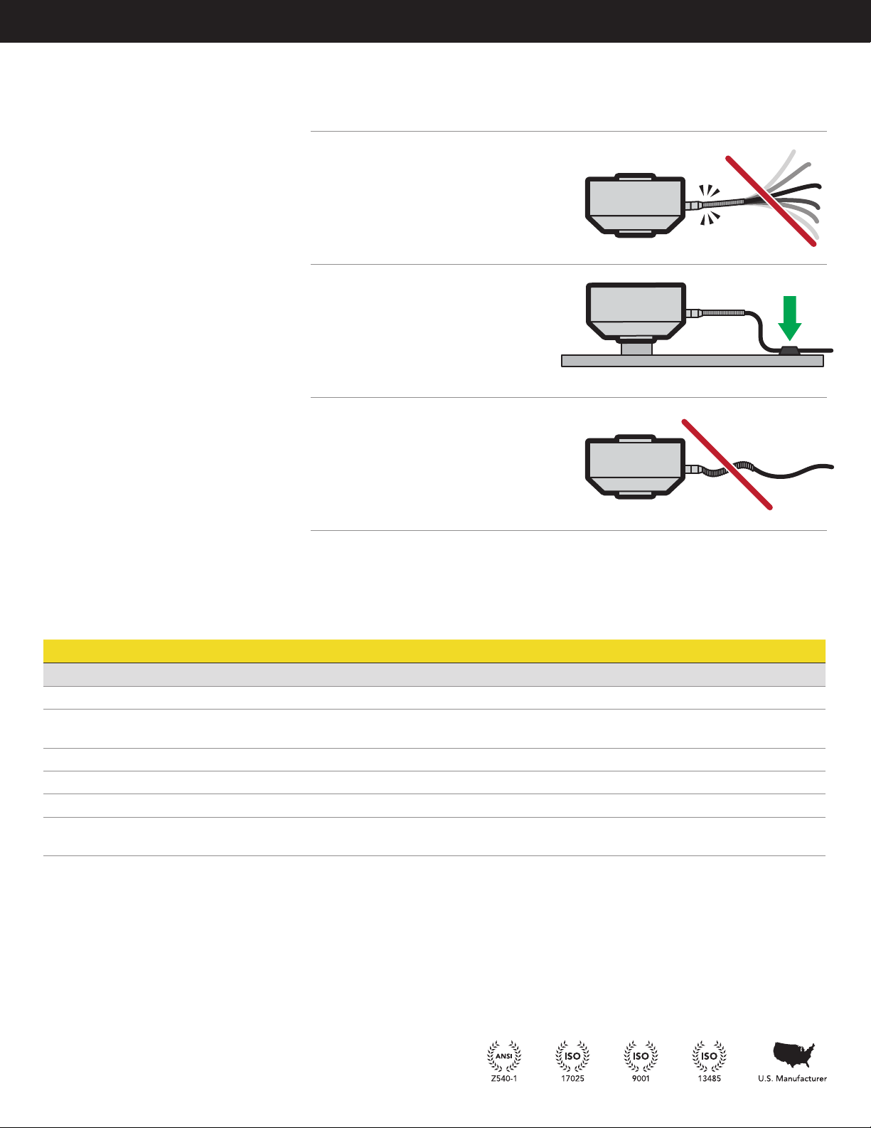
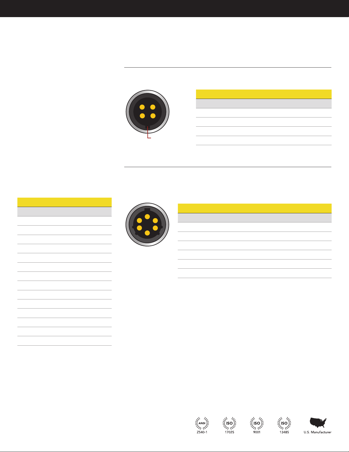
Shield Usage and Connections
• Cable shielding should be grounded on one
end, either the sensor side or instrument
side to avoid ground loops.
• A shield connection listed as floating on a
sensors spec sheet means the cable shield is
not connected on the sensor side and may
be connected on the instrument side
to ground.
Calibration
• A yearly calibration is recommended. But
verification and calibration period shall be
defined based on application, conditions,
endurance and usage.
• FUTEK offers NIST calibrations as well
as A2LA accredited calibrations for total
uncertainty.
• For more information on available
calibrations visit FUTEK calibration web
page at: http://www.futek.com/calibration-
services.aspx
• For recalibration orders visit the FUTEK
recalibration page at: http://www.futek.com/
recalibration.aspx
• An online summary of calibration results
is available at: http://www.futek.com/
calibrationData.aspx
SHUNT
A shunt is an external resistance applied across
two points on the load cell’s Wheatstone
bridge to generate a known, fixed output from
the sensor.
Shunt results can be used to set up instruments
as well as compare changes to the load cell
output over time and usage.
When selecting the appropriate shunt
resistance for your load cell, we recommend a
resistance that generates an output of about
80% of the sensor’s rated output. It is important
to have a shunt resistance that results in an
output that is less than the full output of the
load cell.
An online shunt calculator can be found at
http://www.futek.com/shuntcalc.aspx to find
a resistance that will generate a certain shunt
output level, or to estimate the output for a
known shunt resistance.
Additionally, recommended shunt resistance
levels may be available on the sensor spec
sheet.
TEDS
Transducer Electronic Data Sheet (TEDS)
IEEE1451.4 standard is available for FUTEK
sensors and is utilized by select FUTEK
instruments.
Through the use of TEDS load cell calibration
information can be stored with sensor, or
sensor cable, for use with TEDS capable
instruments.
FUTEK utilizes the Bridge Sensor template 33
for the LCF family.
The following FUTEK instruments are TEDS and
LCF compatible:
IPM Series
Panel Mount Display
IHH Series
Handheld Instrument
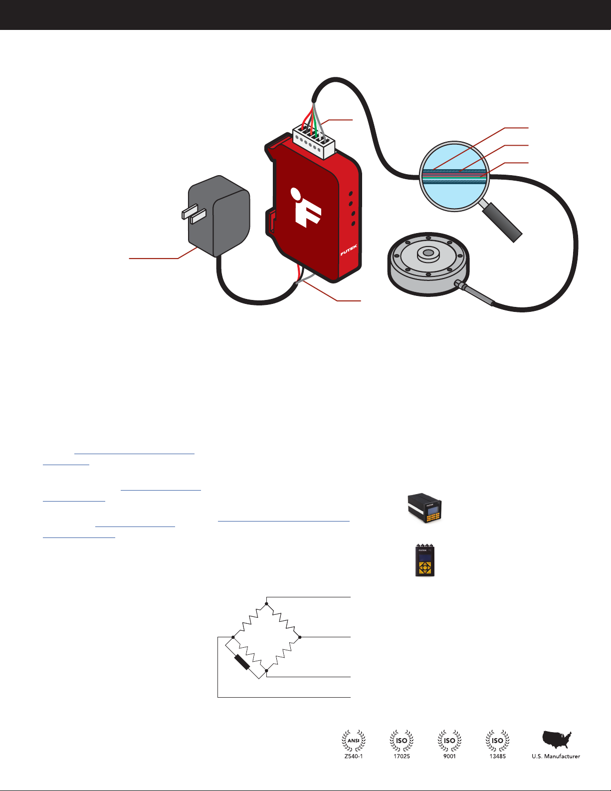
Bridge Sensor
XXXΩ
+ Excitation
+ Signal
Shunt Cal
– Signal
– Excitation
Shield
Power Supply
Shield Jacket
Shield
Wires