Futek TFF Series User manual

Sensor Solutions Source
Load · Torque · Pressure · Multi-Axis · Calibration · Instruments · Software
www.futek.com
TFF Series
Torque Sensor Family Manual

TFF Torque Sensor Family Manual 2
Sensor Solution Source
Load · Torque · Pressure · Multi-Axis · Calibration · Instruments · Software
www.futek.com
Table of Contents
Key Features ......................................3
Mechanical Installation ..............................4
Mounting and Installation............................5
Maximum Installation Torque .........................6
Cable Care and Routing .............................7
Electrical Installation ................................8
Shield Usage and Connections........................9
Calibration........................................9
Troubleshooting ..................................10
Further Support Resources ..........................12

Sensor Solution Source
Load · Torque · Pressure · Multi-Axis · Calibration · Instruments · Software
www.futek.com
Key Features
TFF Torque Sensor Family Manual 3
The TFF (Torque Flange to Flange) sensor series
measures the torque between a stationary or
resistive moment or torque. Since the TFF sensor
measures a static moment, it does not fully
rotate with an applied torque.
The updated TFF400 has a built-in overload
protection system allowing up to 300% for the 5
to 1,000 in-oz capacities, and 150% for the 100
to 500 in-lb capacities.
The standard TFF line can be modified or
customized to meet your requirements. Contact
FUTEK’s application team for further information.
The TFF series features a through hole design
with tapered edges, which helps to center the
sensor.
Although not officially part of the TFF line,
our QTA141 is a unique micro reaction torque
sensor. It features a 1Nm capacity with a 0.866
in. outer diameter and 0.394 in. height.
The through hole design allows for a shaft (or
other rotating items) to pass through the sensor.
In order to create the optimal solution for your
application, our team has designed a large
selection of fixtures for the sensor including
square-drives, and flanges.

Sensor Solution Source
Load · Torque · Pressure · Multi-Axis · Calibration · Instruments · Software
www.futek.com
Mechanical Installation
The following precautions should be observed
to avoid damage to the TFF sensor during
installation and usage.
• Avoid conditions that exceed the sensor’s
spec sheet IP rating.
• Store in a dry area without fixtures.
• Sensors with overload protection wire
cut gaps, if exposed, should be regularly
cleaned to maintain proper deflection
path.
1. Do not pull on or carry sensor
by cable.
2. Monitor sensor output for
effects on zero output during
installation to avoid damage.
3. Install in a dry, clean
environment.
4. TFF325 and TFF350 are OEM
type sensors and require extra
care in handling as they have
exposed elements.
TFF Torque Sensor Family Manual 4
OK
Non-loading surface (cover), do not
contact while loading
Active end (top of loading flexure)
Fixed end (bottom support of flexure)

TFF Torque Sensor Family Manual 5
Sensor Solution Source
Load · Torque · Pressure · Multi-Axis · Calibration · Instruments · Software
www.futek.com
1. TFF325 and TFF350 come with
dowel pin holes to help with
alignment.
2. TFF325 had additional flats
that can assist with fixture
attachment and sensor
placement.
3. Loading surface must be flat
and inline.
4. Support surfaces must be flat
and inline
Mounting and Installation
• Refer to the sensor spec sheet for
information on proper torque sensor
orientation for best performance and
to limit cable influence.
• Measurements are called out on the
sensor spec sheet and have the following
tolerances based on the number of decimal
points present.
DECIMAL FORMAT TOLERANCE
0.x ±0.1"
0.xx ±0.01"
0.xxx ±0.005"
0.xxxx ±0.001"
• Bolt hole placements are called out in a Bolt
Circle Diameter (BCD) which is an imaginary
circle passing through the centers of all the
bolts in a round pattern.
• Maintain inline torque if the fixture doesn’t
include coupling or flexible joints
90°

TFF Torque Sensor Family Manual 6
Sensor Solution Source
Load · Torque · Pressure · Multi-Axis · Calibration · Instruments · Software
www.futek.com
INSTALLATION TORQUE
MODEL CAPACITY RECOMMENDED TORQUE
(lbf-in)
TFF325 20 in-oz 3-5
50 in-oz 3-5
12 in-lb 5-10
50 in-lb 10-15
100 in-lb 15-20
TFF350 100 in-lb 10-15
500 in-lb 20-30
1300 in-lb 40-50
TFF400 5 in-oz 5-10
10 in-oz 5-10
50 in-oz 5-10
160 in-oz 15-20
400 in-oz 15-20
1000 in-oz 15-20
100 in-lb 25-30
200 in-lb 25-30
500 in-lb 25-30
TFF425 5 in-oz 5-10
10 in-oz 5-10
50 in-oz 5-10
160 in-oz 15-20
400 in-oz 15-20
1000 in-oz 15-20
100 in-lb 25-30
200 in-lb 25-30
500 in-lb 25-30
TFF500 100 in-lb 5-10
TFF600 2000 in-lb 150-200
10000 in-lb 150-200
Maximum moments and
off-axis loading
• Use extraneous load information to
determine if the sensor can withstand any
unavoidable off-axis loads and moments.
Extraneous load information can be found
at: http://www.futek.com/extraneous-load-
factor
• An Extraneous how-to-guide can be
found at: http://www.futek.com/files/
pdf/Extraneous_Load_Factors/How_To_
Calculate_Extraneous_Loads.pdf
• Torsional stiffness is an indication of how
much torque will result in one radian of
angular deflection. The torsional stiffness
can be found on the sensor’s spec sheet.
• Note: To avoid damage when applying
torque, only constrain the flange attached to
the fastener.

TFF Torque Sensor Family Manual 7
Sensor Solution Source
Load · Torque · Pressure · Multi-Axis · Calibration · Instruments · Software
www.futek.com
Cable Care and Routing
• Cable material type and length can be
found online in the sensor description page.
1. Avoid stress and movement on cable to
avoid damage.
2. Properly secure sensor cable to limit cable
movement influence
3. Avoid bending the strain relief. Bends in
the cable should not exceed a radius of 10
times the diameter of the sensor cable for
dynamic, or moving, applications. When
permanently routing a cable in a static
installation, the minimal bend radius
should not fall below 2-3 times the
diameter of the cable.

TFF Torque Sensor Family Manual 8
Sensor Solution Source
Load · Torque · Pressure · Multi-Axis · Calibration · Instruments · Software
www.futek.com
Electrical Installation
WIRING AND CONNECTIONS
• The TFF torque sensor series utilizes a
four-wire bare lead connection, a four-pin
Lemo connection or a DB9 with TEDS.
• Standard four-wire connections are
+Excitation, –Excitation, +Signal, and
–Signal. The standard coloring code for
the above listed connections are Red,
Black, Green, and White.
• Note: the Lemo connection is considered
a quick release connection and is slipped
out rather than twisted for removal.
• A right angle exit Lemo connector is
available. Note: Connection position is
not standard, and position may vary.
WC1
STANDARD 4-WIRE
WC1
Bridge Sensor
XXXΩ
+ Excitation (Red)
+ Signal (Green)
– Signal (White)
– Excitation (Black)
Shield (Sensor Body)
WC1S
w/shield
Bridge Sensor
XXXΩ
+ Excitation (Red)
+ Signal (Black)
– Signal (Green)
Voltage Output (+) (Green)
– Excitation (White)
WC3
Bridge Sensor
XXXΩ
WC6
Bridge Sensor
XXXΩ
Power Supply (+) (Red)
Current Output (+) (Green)
Power Supply (+) (Red)
Ground (–) (Black)
WC5
Bridge Sensor
XXXΩ
+ Excitation (Red)
+ Signal (Green)
– Signal (White)
– Excitation (Black)
Shield (Floating)
Shield (Floating)
TFF500 Non-Amplified
CC4
TFF EXCITATION VOLTAGE LEVELS
SENSOR FAMILY MAX. EXCITATION
TFF325 18 V
TFF350 18 V
TFF400 18 V
TFF425 18 V
TFF500 18 V
TFF600 18 V
DB9 9-PIN
PIN COLOR DESCRIPTION
1Green + Signal out
2Red + Excitation
5Orange TEDS data
6White – Signal out
7Black – Excitation
9Blue TEDS gnd
LEMO 4-PIN
PIN COLOR DESCRIPTION
1Red + Excitation
2Green + Signal
3White – Signal
4Black – Excitation
PT02E-10-6P, PC04E-10-6P or
PT02H-10-6P RECEPTACLE
PT06A-10-6S-SR, PC06E-10-6S-SR
MATING CONNECTOR
WHITE
BLACK
GREEN
RED
ALIGN WITH KEY EGG.0B.304.CLL
RECEPTACLE
FGG.0B.304.CLAD35
GREEN
RED
WHITE
BLACK
KEY
DR-4S-6 RECEPTACLE
DP-4S-1 MATING
CONNECTOR
DIN #43650
B
A
C
D
C
D
B
A
5
9 8 7 6
4321
1
6 7 8 9
2345
1 8
9 15
3
FB
A
E C
D
3
BF
A
CE
D
2 3
1 4
3 2
4 1
C B
D A
B C
A D
B C
A D
Key
Align with key

Power Supply
Shield Jacket
Shield
Wires
TFF Torque Sensor Family Manual 9
Sensor Solution Source
Load · Torque · Pressure · Multi-Axis · Calibration · Instruments · Software
www.futek.com
Shield Usage and Connections
• Cable shielding should be grounded on one
end, either the sensor side or instrument
side to avoid ground loops.
• A shield connection listed as floating on a
sensor’s spec sheet means the cable shield
is not connected on the sensor side and may
be connected on the instrument side
to ground.
• Shield connections are located
on the sensor’s spec sheet.
Calibration
• A yearly calibration is recommended. But
verification and calibration period shall be
defined based on application, conditions,
endurance and usage.
• FUTEK offers NIST calibrations as well
as A2LA certified calibrations for total
uncertainty.
• For more information on available
calibrations visit FUTEK calibration web
page at: http://www.futek.com/calibration-
services.aspx
• For recalibration orders visit the FUTEK
recalibration page at: http://www.futek.com/
recalibration.aspx
• An online summary of calibration results
is available at: http://www.futek.com/
calibrationData.aspx
SHUNT
A shunt is an external resistance applied across
two points on the load cell’s Wheatstone
bridge to generate a known, fixed output from
the sensor.
Shunt results can be used to set up instruments
as well as compare changes to the load cell
output over time and usage.
When selecting the appropriate shunt
resistance for your load cell, we recommend a
resistance that generates an output of about
80% of the sensor’s rated output. It is important
to have a shunt resistance that results in an
output that is less than the full output of the
load cell.
An online shunt calculator can be found at
http://www.futek.com/shuntcalc.aspx to find
a resistance that will generate a certain shunt
output level, or to estimate the output for a
known shunt resistance.
TEDS
Transducer Electronic Data Sheet (TEDS)
standard is available for FUTEK sensors and is
utilized by select FUTEK instruments.
Through the use of TEDS load cell calibration
information can be stored with sensor, or
sensor cable, for use with TEDS capable
instruments.
FUTEK utilizes the Bridge Sensor template 33
for the TFF family.
The following FUTEK instruments are TEDS and
TFF compatible:
IPM650
Panel Mount Display
IHH500
Handheld Instrument
Bridge Sensor
XXXΩ
+ Excitation
+ Signal
Shunt Cal
– Signal
– Excitation

TFF Torque Sensor Family Manual 10
Sensor Solution Source
Load · Torque · Pressure · Multi-Axis · Calibration · Instruments · Software
www.futek.com
Troubleshooting
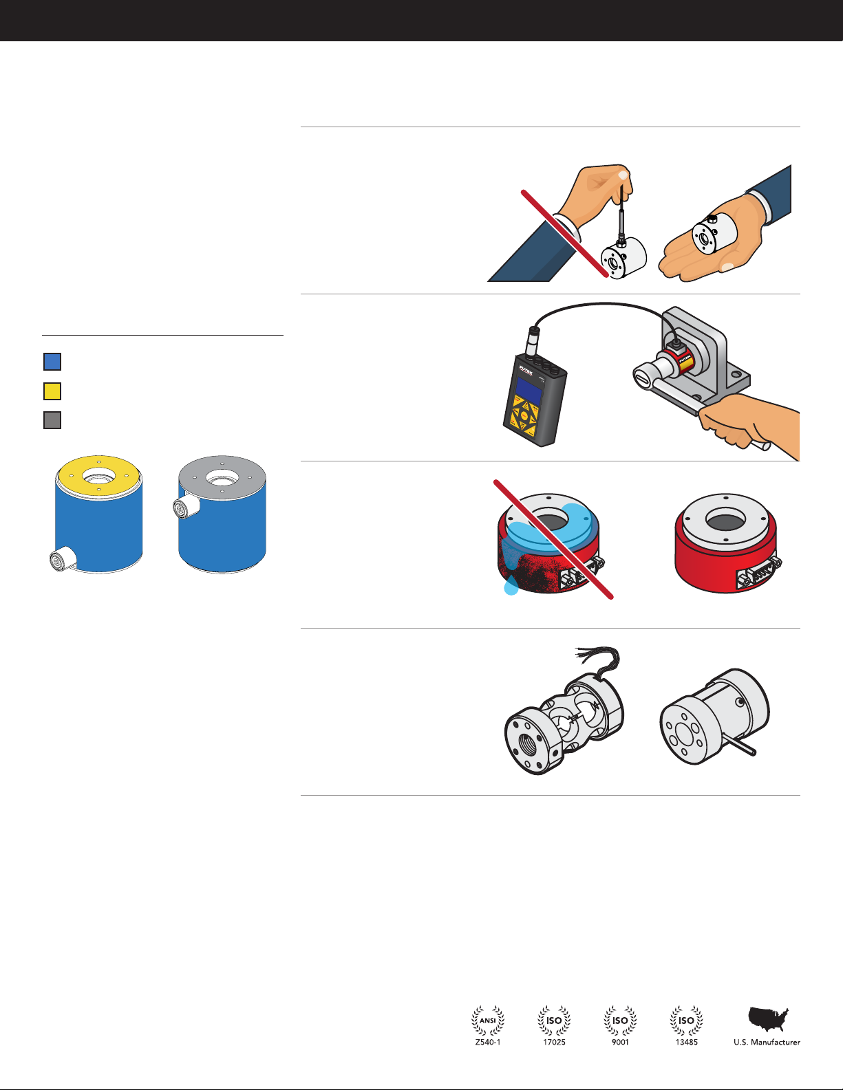
When troubleshooting, we recommend that the sensor be removed from any fixtures. In order to confirm that that sensor
is operating correctly, we suggest placing the sensor on a firm surface, and to apply a known load.
We also recommend using a volt meter with a clean power supply to confirm the sensor is operating correctly.
SYMPTOM POSSIBLE CAUSE CHECK REPAIRABILITY
High zero output • Sensor is under preload
• Sensor has been overloaded from too
much load, off axis load, or moment.
• Fixtures or bolting stress for causes of
pre-load.
• Loading and support placement for off
axis loads.
• Avoid excessive moments during
installation.
• Overload shift would not be repairable.
• If zero offset is stable it may be
possible to use sensor by use of Tare
or subtracting zero from sequential
readings.
Non-responsive
zero output
• Sensor or instrument is not powered.
• Sensor is not properly connected.
• Load is not displaced properly onto
sensor.
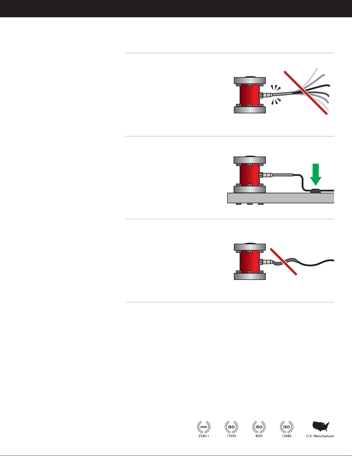
• Sensor is not supported correctly and
not allowing deflection to occur to
measure load.
• Internal disconnect or short.
• Power and wiring to sensor and instru-
ment.
• Sensor bridge resistance for possible
opens or shorts.
• Perform continuity test on cable.
• Load is placed correctly on sensor
loading surface.
• Sensor loading surface is not obstruct-
ed or supported and able to flex under
load.
• Sensor support is not giving while
sensor is loaded.
• Internal disconnections or shorts would
not be available for repair.
• Sensor cable repair may be available
if disconnect or short is not too close
to sensor.
Non-responsive
high output
• Sensor is disconnected from
instrument.
• An opening has occurred in sensor or
cable connection.
• Sensor has been overloaded and de-
formed causing permanent high stress
on internal gauges.
• Fixture, applied load, or mounting is
causing a high pre-load on sensor.
• Power and wiring to sensor and instru-
ment.
• Sensor bridge resistance for possible
opens or shorts.
• Perform continuity check on cable.
• Sensor zero output to see if sensor
returns to zero or has a high zero load
output due to overloading.
• Remove load and loosen mounting
bolts or fixtures to check if sensor is
being preloaded.
• Overload shift would not be repairable.
• Internal disconnections or shorts would
not be available for repair.
• Sensor cable repair may be available
if disconnect or short is not too close
to sensor.
Incorrect output for
applied load
• Load is not applied correctly to sensor
loading surface or is off axis.
• Fixtures are not secure or obstruct
loading.
• Sensor loading surface is not able to
deflect with applied load.
• Sensor support is not ridged and firm.
• Incorrect sensor output is utilized.
• Placement of load on sensor.
• Fixtures are not impeding ability to
load.
• Support surface is not giving with
applied load.
• Calibration verified outputs are being
used.
• Recalibration is available for confirma-
tion of sensor performance.

TFF Torque Sensor Family Manual 11
Sensor Solution Source
Load · Torque · Pressure · Multi-Axis · Calibration · Instruments · Software
www.futek.com
SYMPTOM POSSIBLE CAUSE CHECK REPAIRABILITY
Zero output drift • Unstable power supply, or noisy power
supply, to sensor.
• Sensor exposed to temperature
change.
• Sensor exposed to pre-load from
fixture or mounting.
• Sensor exposed to liquid or humidity.
• Stability of power supply and noise
levels.
• For temperature changes or unevenly
distributed temperature changes.
• Possible loose fixtures and bolts
• Internal damage from liquid exposure
is not repairable.
• Recalibration is available for confirma-
tion of sensor performance.
Creep in output
while under load
• Load or fixtures are not stable.
• Power supply is unstable or noisy.
• Sensor is exposed to temperature
change.
• Sensor support is not rigid and firm.
• Sensor exposed to liquid or humidity.
• Stability of power supply and noise
levels.
• Fixtures for stability.
• For temperature changes or unevenly
distributed temperature changes.
• Confirm support surfaces are not giv-
ing while under load.
• Internal damage from liquid exposure
is not repairable.
• Recalibration is available for confirma-
tion of sensor performance.
Noisy or unstable
output
• Power supply is noisy.
• Load is not stable.
• Sensor or cable is placed close to high
power equipment.
• Sensor or instrument is exposed to
ground loop with other equipment
grounds.
• Power supply stability.
• Load is stable and fixtures are secure.
• Reroute cables away from high power
equipment.
• Confirm wiring and grounds are not
connected to unintended equipment
ground.
• There are no active electronics in a
load cell, such as capacitors or IC chips
that may contribute to noise.

TFF Torque Sensor Family Manual 12
10 Thomas, Irvine, CA 92618 USA
Tel: (949) 465-0900
Fax: (949) 465-0905
www.futek.com
Drawing Number: EM1040
Further Support Resources
• Support information for FUTEK instruments can be
found online at: http://www.futek.com/manuals.aspx
• A one year recalibration is recommended. But
verification and calibration period shall be defined
based on application, conditions, endurance and
usage. Calibration data may be available online at
http://www.futek.com/calibrationData.aspx
• To send in your sensor or system for recalibration
visit our FUTEK calibration web page at: http://
www.futek.com/recalibration.aspx
• FUTEK Technical Support may be reached at: http://
www.futek.com/contact.aspx?form=technical
• To send in your sensor or system for evaluation and
repair visit our FUTEK RMA web page at: http://
www.futek.com/contact.aspx?form=repair
• FUTEK contact information can be found online at:
http://www.futek.com/contact
• Warranty information can be found online at
http://www.futek.com/remWarranty.aspx
This manual suits for next models
6
Table of contents
Other Futek Accessories manuals
Popular Accessories manuals by other brands

Tekkeon
Tekkeon myPower ALL Plus MP3450i R2 Web and catalog content

NORDIQZENZ
NORDIQZENZ PB20000 instruction manual

Cardinal
Cardinal SMARTCELL 825D Installation and technical manual

Nordmann Engineering
Nordmann Engineering NRC-5V installation instructions

IFM
IFM SB1 Series operating instructions

BOMANN
BOMANN KSG 235 instruction manual