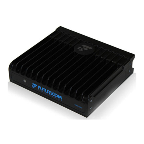
Futurecom VRX1000 Operating and installation instructions

Futurecom Systems Group, ULC
VRX1000
Functional Description

8K087X02 R13
VRX1000 Functional Description
January 2020
Page 2 of 74
NOTES

8K087X02 R13
VRX1000 Functional Description
January 2020
Page 3 of 74
Contents
Contents............................................................................................................................. 3
List of Tables................................................................................................................... 6
List of Figures.................................................................................................................. 6
Manual Revisions............................................................................................................ 7
Computer Software Copyrights ...................................................................................... 8
Disclaimer ....................................................................................................................... 8
Trademarks..................................................................................................................... 8
Introduction ....................................................................................................................... 9
Firmware ......................................................................................................................... 9
VRX1000 Compatibility................................................................................................. 10
VRX1000 Models.......................................................................................................... 11
Frequency Band of Operation........................................................................................11
Cross-Band..................................................................................................................11
In-Band........................................................................................................................12
Band Locking ...............................................................................................................13
VRX1000 Features Supported on Motorola Infrastructure................................................14
‘DVRS/VRX1000 Enabled’ PSUs ...................................................................................15
‘VRX1000 Enabled’ PSU Features Supported on Non-Motorola Infrastructure.......... 16
VRX1000 Operation and Basic Features..................................................................... 17
VRX1000 Status Display ...............................................................................................17
‘DVRS/VRX Enabled’ Mobile Radio TGs / Channels .......................................................17
‘DVRS/ VRX Disabled’ Mobile Radio TGs / Channels ......................................................18
Activating the VRX1000 via the MSU Control Head.........................................................18
Automatic VR Activation (AVRA)....................................................................................18
Remote Activation of the VRX1000.............................................................................. 19
VRX1000 Modes of Operation...................................................................................... 20
OFF Mode....................................................................................................................21
SYSTEM Mode.............................................................................................................21
LOCAL Mode ...............................................................................................................22
Selecting VRX1000 Mode and Channel....................................................................... 23
In Car Monitor (ICM)..................................................................................................... 24
Primary / Secondary Operation Basics ........................................................................ 25
Permanent Primary Activation .......................................................................................27
Permanent Primary Deactivation....................................................................................27
Legacy Mobexcom II Voting Compatibility Mode .............................................................27
VRX1000 Voting Compatibility Modes............................................................................27
MSU Scan..................................................................................................................... 28
MSU ISSI Roaming....................................................................................................... 29
Unsupported Features.................................................................................................. 29

8K087X02 R13
VRX1000 Functional Description
January 2020
Page 4 of 74
P25 Digital Mode Operation........................................................................................... 31
PSU Affiliation............................................................................................................... 32
Group Calls ................................................................................................................... 32
MSU Priorities............................................................................................................... 32
PSU Proxy Request Priorities....................................................................................... 32
MSU Voice and Signaling Proxy Interactions............................................................... 33
Talk Group Proxying..................................................................................................... 33
Talk Group Translation................................................................................................. 33
Private Calls.................................................................................................................. 34
PSU Talk Permit Tones ................................................................................................ 34
Status Broadcast........................................................................................................... 35
Local Mode Indication................................................................................................... 35
Radio Check / Inhibit..................................................................................................... 35
P25 Trunking OTAR...................................................................................................... 35
Patch............................................................................................................................. 36
Dynamic Regrouping .................................................................................................... 37
Phone Interconnect....................................................................................................... 37
Adaptive Power Control................................................................................................ 37
Digital Audio Buffering .................................................................................................. 37
P25 Encryption.............................................................................................................. 38
Remote VRX1000 Activation and Steering by PSU Call Alert (Page)......................... 39
Emergency in Digital Mode........................................................................................... 41
Emergency Alarm.........................................................................................................41
Emergency Call............................................................................................................42
Emergency Revert through VRX1000.............................................................................42
Emergency Revert through PSU....................................................................................42
Emergency operation during TG Translation...................................................................42
Fireground (FG) Signaling ............................................................................................ 43
PSU IV&D..................................................................................................................... 43
PSU Location Reporting ............................................................................................... 43
PSU Call Alert............................................................................................................... 43
PSU Message............................................................................................................... 43
PSU Status Update and Status Request...................................................................... 43
Automatic PSU Revert to Talk Around (TA)................................................................. 43
PSU Group Services..................................................................................................... 44
Group Text...................................................................................................................44
Group Alias Update ......................................................................................................45

8K087X02 R13
VRX1000 Functional Description
January 2020
Page 5 of 74
Personnel Accountability .............................................................................................. 45
DVRS PSU Authentication............................................................................................ 45
Digital Mode –P25 Conventional Support ................................................................... 46
P25 Digital VRX1000 Mode with P25 Conventional Mode Selected on MSU.....................46
P25 Digital VRX1000 Mode (Generic P25 PSUs) with P25 Trunked (FDMA) Mode Selected
on MSU........................................................................................................................47
Digital Mode –P25 Enhanced Trunking Features Support ......................................... 48
P25 Digital VRX1000 Mode with P25 Conventional Mode Selected on MSU.....................48
P25 Digital VRX1000 Mode with P25 Trunked (FDMA) Mode Selected on MSU ...............49
Forced Analog Mode ...................................................................................................... 50
Forced Analog All DVR Mode- Operation and Programming Overview...................... 50
Forced Analog Mode –Summary of Features ............................................................. 51
Forced Analog VRX1000 Mode with P25 Trunking TDMA Mode Selected on MSU ...........51
Forced Analog VRX1000 Mode with 3600 Trunking Mode Selected on MSU ....................52
Forced Analog VRX1000 Mode with Conventional Analog Mode Selected on MSU...........53
Analog Mode Operation ................................................................................................. 54
VRX1000 Channel Setup for Analog Mode.................................................................. 54
Group Calls ................................................................................................................... 54
Emergency in Analog Mode.......................................................................................... 55
Emergency Alarm.........................................................................................................55
Emergency Call............................................................................................................55
Emergency Revert........................................................................................................56
Analog Audio Buffering ................................................................................................. 56
Tactical Public Safety (TPS)......................................................................................... 56
Fireground (FG) Signaling ............................................................................................ 56
Remote VRX1000 Activation via DTMF....................................................................... 57
P25 Encryption in Analog Mode................................................................................... 57
Leading & Trailing Tones.............................................................................................. 57
Mobile Mode Steering via PL/DPL................................................................................ 58
Steering and Emergency...............................................................................................58
MSU Operating onTDMA (P25, Phase 2) ................................................................... 58
Analog Mode –Summary of Features.......................................................................... 59
Analog VRX1000 Mode with P25 Trunking Mode (FDMA) Selected on MSU ....................59
Analog VRX1000 Mode with P25 Conventional Mode Selected on MSU...........................60
Analog VRX1000 Mode with Conventional Analog Mode Selected on MSU......................61
Analog VRX1000 Mode with 3600 Baud Analog or Digital Trunking Mode Selected on MSU
....................................................................................................................................62
Analog VRX1000 Mode with P25 Phase II (TDMA) Trunking Mode Selected on MSU .......63
Mixed VRX1000 Mode..................................................................................................... 64
Special Features Support .............................................................................................. 65

8K087X02 R13
VRX1000 Functional Description
January 2020
Page 6 of 74
TPS Signaling ............................................................................................................... 65
Contact Information........................................................................................................ 66
Glossary........................................................................................................................... 69
Index................................................................................................................................. 72
List of Tables
Table 1 VRX1000 Compatible MSUs............................................................................... 10
Table 2 VRX1000 vs Infrastructure Compatibility ............................................................ 10
Table 3 VRX1000 Features vs Type of PSU.................................................................... 14
Table 4 DVRS/VRX1000 Enabled PSU Models............................................................... 15
Table 5 'VRX1000 Enabled' PSU Features Supported on Non-Motorola Infrastructure. 16
Table 6 OFF Mode Operation........................................................................................... 21
Table 7 SYSTEM Mode Operation................................................................................... 21
Table 8 LOCAL Mode Operation...................................................................................... 22
Table 9 Primary VRX1000 Definitions.............................................................................. 26
Table 10 VRX1000 Voting Compatibility .......................................................................... 27
Table 11 MSU Priorities.................................................................................................... 32
Table 12 PSU Proxy Request Priorities ........................................................................... 32
Table 13 Inbound P25 Encryption Rules.......................................................................... 38
Table 14 Outbound P25 EncryptionRules....................................................................... 38
Table 15 MSU MIC PTT P25 Encryption Rules ............................................................... 38
Table 16 Typical Remote Steering Scenarios.................................................................. 40
List of Figures
Figure 1 Cross-Band VRX1000 - Conceptual Diagram ................................................... 11
Figure 2 In-Band VRX1000 - Conceptual Diagram.......................................................... 12

8K087X02 R13
VRX1000 Functional Description
January 2020
Page 7 of 74
Manual Revisions
Rev #
Date
By
Notes & References
0
November 11, 2014
KG
Original Release
1
November 20, 2014
KG
Updated MIL-STD-810G
2
July 22, 2015
KG
Firmware R1.20/SR7.15.5 Update
3
October 15, 2015
KG
Firmware R1.21/Q4 SER 2015
Update
4
February 11, 2016
KG
Firmware R1.22/Q1 SER 2016
Update
5
October 12, 2016
SN
Firmware R1.30/ SR7.17 Update
6
October 19,2016
SN
Removed CH Firmware version.
Updated VRX10000 features for MSU
mode tables
7
April 17, 2017
AJK/SN
Firmware R1.40/ SR7.17.5 update
8
May 1, 2017
AJK/SN
Updated APX8500 Firmware version
9
January 22, 2018
AJK/SN
Firmware R1.41/SR7.18 Update
10
June 12, 2018
AJK/SN
Firmware R1.42/SR7.18.5 Update
11
January 29, 2019
AJK/SN
Firmware R1.43/SR 7.18.8 Update
12
July 24, 2019
AJK/SN
Firmware R1.50/SR 7.19.2 Update
13
January 22, 2020
AJK/SN
Firmware R1.51/SR 7.19.2 Update

8K087X02 R13
VRX1000 Functional Description
January 2020
Page 8 of 74
Computer Software Copyrights
The products described inthis manualinclude copyrighted Futurecom computer programs
stored insemiconductor memories or other media. Laws in the United States, Canada and
other countries preserve for Futurecom certain exclusive rights for copyrighted computer
programs, including but not limited to, the exclusive right to copy or reproduce inany form
the copyrighted computer programs. Any copyrighted computer program contained in the
Futurecom products described in this manual may not be copied, reproduced, modified,
reverse-engineered, or distributed in any manner without the express written permission
of Futurecom. The purchase of Futurecom products shall not be deemed to grant either
directly or by implication, estoppels, or otherwise, any license under the copyrights,
patents or patent applications of Futurecom, except for the normal non-exclusive license
to use that arises by operation of law in the sale of a product.
Disclaimer
The information in this document is carefully examined and is believed to be entirely
reliable. However, no responsibility is assumed for inaccuracies. Futurecom Systems
Group, ULC. reserves the right to make changes to any products herein to improve
reliability, function or design. Futurecom does not assume any liability arising out of the
application or use of any product or circuit described herein.
Trademarks
Futurecom, PDR8000, the Futurecom Logo and the Stylized FC logo are registered
trademarks of Futurecom Systems Group, ULC. All other trademarks are the property of
their respective owner. © 2020 Futurecom Systems Group, ULC. All rights reserved.
MOTOROLA, MOTO, MOTOROLA SOLUTIONS and the Stylized M logo are trademarks
or registered trademarks of Motorola Trademark Holdings, LLC and are used under
license. All other trademarks are the property of their respective owners.

8K087X02 R13
VRX1000 Functional Description
January 2020
Page 9 of 74
Introduction
The VRX1000 is a simplex radio coverage extender, which is interfaced to a compatible
remote mount Motorola Solutions Mobile Radio (see Table 1) and enables Portable
Subscriber Units (PSUs) to be used in areas where only Mobile Subscriber Unit (MSU)
coverage is available and PSU coverage is either intermittent or completely absent.
Installed in the trunk of a car, fire truck, armored vehicle, ambulance, the VRX1000
extends radio communications to the PSU users who are outside of the vehicle, inside a
nearby building or in any marginal portable radio coverage areas. The VRX1000 extends
voice (analog, P25 clear or P25 encrypted) communications and supports key trunking
system features. The VRX1000 can be configured to provide various advanced options to
the users.
Unlike the Digital Vehicular Repeater System (DVRS), which can be configured for either
simplex or full duplex operation, the VRX1000 supports only simplex mode and can’t
extend local PSU-to-PSU communications. When using the VRX1000, the Local PSUs
communicate with each other in Talk Around (TA) mode and with the System users via
the VRX1000.
The DVRS is required in applications where local radio coverage extension is needed
(between the Local PSUs) in addition to the System-to-Local PSU and Local PSU-to-
System coverage extension.
This document only describes the VRX1000 operation.
Firmware
The VRX1000 Operation described in this Document requires the following
Firmware:
APX2500/APX4500/APX6500/APX7500/APX8500- firmware release: Host R20.02.00 or
later
APX Mobile Radios operating as the host mobile for the VRX1000 require subscriber
option GA00631 for operation.
APX2000/APX4000/APX6000/APX7000/APX8000 –firmware release R20.02.00 or later.
APX Portable Radios operating through a DVR/VRX1000, utilizing the DVR/VRX1000
Enabled digital feature set require subscriber option QA00631.
VRX1000 must be loaded with application firmware 4C083X11 R1.51 or later.
Tweaker Programming software version 1.22 or later.

8K087X02 R13
VRX1000 Functional Description
January 2020
Page 10 of 74
VRX1000 Compatibility
The Vehicular Radio Extender (VRX1000) is designed to be seamlessly interfaced to the
following Motorola Solutions Mobile Radios:
Mobile Radio Model
Firmware Requirements
Notes
APX2500
R19 R20.02.00 or later
R
Requires option GA00631
APX4500
R20.02.00 or later
APX6500
R20.02.00 or later
APX7500
R20.02.00 or later
APX8500
R20.02.00 or later
NOTE:
Mobile Radio must be configured as Remote Mount in order to be compatible with the
VRX1000.
Table 1 VRX1000 Compatible MSUs
The VRX1000 is a simplex radio coverage extender, which is interfaced to a compatible
remote mount Motorola Solutions Mobile Radio and enables Portable Subscriber Units
(PSU) to be used in areas where only Mobile Subscriber Unit (MSU) coverage is available
and PSU coverage is either intermittent or completely absent.
Installed in the trunk of a car, fire truck, armored vehicle, ambulance, the VRX1000
extends radio communications to the PSU users who are outside of the vehicle, inside a
nearby building or in any marginal portable radio coverage areas. The VRX1000 extends
voice (analog, digital clear or digitalencrypted) communications and supports key trunking
system features. The VRX1000 can be configured to provide various advanced options to
the users.
Table 2 provides information on the VRX1000 infrastructure compatibility options.
FIXED NETWORK TYPE / MOBILE RADIO MODE
Portable
Radio Type /
Mode
Conventional
Analog incl.
Mixed Receive
Conventional
P25 incl.
Mixed Receive
3600 Analog /
Digital
Trunking
9600 P25
Trunking
FDMA
9600 P25
Trunking
TDMA
Conventional
Analog
YES
A
YES
A/M
YES
A
YES
A/M
YES
A
Generic P25
Conventional
NO
YES
D/M/FA
NO
YES
D/M/FA
NO
P25
Conventional
‘DVRS
Enabled’
YES
FA/FA-All
YES
D/FA/FA-
All/M
YES
FA/FA-All
YES
D/FA/FA-
All/M
YES
D/FA/FA-
All/M
Table 2 VRX1000 vs Infrastructure Compatibility
VRX Channel Types:
A = Analog, D = Digital, M = Mixed, FA = Forced Analog, FA-All=Forced Analog All
(See Part II of this manual)

8K087X02 R13
VRX1000 Functional Description
January 2020
Page 11 of 74
VRX1000 Models
Frequency Band of Operation
Depending on the frequency band of operation of the APX Mobile Subscriber Unit (MSU)
and VRX1000, the VRX1000 models are classified as follows:
•In-Band –when the MSU and VRX1000 operate in the same frequency band.
•Cross-Band –when the MSU and VRX1000 operate in two different frequency
bands.
Cross-Band
Cross-Band VRX1000 models do not include any filters on the MSU side since the MSU
and VRX1000 are not intended to simultaneously operate in the same frequency band. In
single band MSU configurations the MSU and VRX1000 operate in different frequency
bands.
In dual band MSU configuration either the MSU & VRX1000 operate in 3 different
frequency bands or one of the MSU frequency bands is locked out when VRX operation
is enabled as shown on Figure 1.
Figure 1 Cross-Band VRX1000 - Conceptual Diagram

8K087X02 R13
VRX1000 Functional Description
January 2020
Page 12 of 74
In-Band
The in-band VRX1000 models are equipped withtwo sets of filters, which are required in
order to ensure interference-free operation when both the MSU and VRX1000 are
transmitting and receiving simultaneously inthe same frequency band. The VRX1000 filter
provides 40 dB isolation on the Mobile radio transmit / receive frequencies. The filter
installed at the output of the MSU is designed to provide 40dB isolation on the VRX1000
TX/RX Frequency Range.
IMPORTANT!
The above filter isolation must be complemented by 30dB minimum antenna
isolation (between the VRX1000 and Mobile Radio antennas) in order to ensure
interference-free operation. It is recommended that the MSU in-band antenna is
mounted on the roof top of the vehicle while the VRX antenna is mounted on the
trunk. Each VRX1000 is shipped equipped with custom filters tuned to the specified
frequency bands –note the frequency range specified on the filter labels.
Programming the VRX / MSU radio to operate on frequencies outside of the original
specified bands may result in intermittent or complete loss of communications.
Frequency changes may require filter retuning or replacement.
NOTE:
The VRX1000 and MSU require two or three (in the case of dual band MSU) separate
antennas.
NOTE:
The In-Band filters connected to the APX MSU are rated for maximum 50 Watts Tx power
and have typical insertion loss of 1.5dB.
Figure 2 In-Band VRX1000 - Conceptual Diagram

8K087X02 R13
VRX1000 Functional Description
January 2020
Page 13 of 74
Band Locking
Two in-band sets of filters –one placed at the MSU Antenna port and another placed at
the VRX1000 Antenna port are required when both the MSU and VRX1000 are configured
to operate in the same frequency band. Thefrequency specific in-band filters are required
in order to prevent interference when the VRX1000 is receiving & MSU is transmitting and
vice versa.
When the in-band filter is not present, the Band Lock feature must be enabled (by using
the Tweaker programming software) in order to prevent VRX1000 operation on MSU
channels that are explicitly using the same frequency band as the VRX1000. On MSU
channels where the frequency band is not explicitly known such as in multi-site trunking
systems, the MSU will be prevented from using frequencies in the same band while the
VRX1000 is active (i.e. in SYSTEM or LOCAL mode). In this case the MSU will no longer
allow roaming to sites using the locked out band. If the MSU is currently on a trunking site
that uses the locked out band, the MSU will roam to another site. If no other sites are
available, the MSU will enter Out Of Range state. When the VRX1000 is inactive (OFF
mode), the MSU frequency band is unlocked.
Inthe case of a single band MSU (suchas the APX4500 and APX6500), in-band VRX1000
applications always require in-band filters and the Band Locking feature must be disabled.
For MSU conventional channels where the band is known and fixed, the VRX1000 restricts
access to channels using the locked out frequency band.
If Band locking is enabled in the VRX1000 and SCAN is enabled in the MSU, the MSU
will skip over any channels in the scan list that are configured to operate in the same
frequency band as the VRX1000.
IMPORTANT!
A 700MHz VRX1000 interfaced to an APX MSU operating on 800MHz as well as an
800MHz VRX1000 interfaced to an APX MSU operating on 700MHz are considered
In-Band applications and either In-Band filters must be provided or band locking
must be enabled (if the MSU is dual band and VRX operation can be supported on
the non 700/800MHz band).
The above is also valid for any of the UHF Bands –if the MSU operates on any of
the UHF ranges, an UHF VRX interfaced to it will require in-band filters to be
installed or band locking to be enabled.

8K087X02 R13
VRX1000 Functional Description
January 2020
Page 14 of 74
VRX1000 Features Supported on Motorola Infrastructure
When the PSU user is out of system radio coverage, the PSU can be switched to a
dedicated VRX1000 channel so that the PSU can communicate via the VRX1000. The
features available to the PSU user depend on the PSU type, programming and selected
mode. The table below specifies what features are supported by the different PSU types.
PSU FEATURE SUPPORT BY
VRX1000
DVRS/VRX
Enabled PSU
[Note 5]
Generic
P25 PSU
Analog PSU
Registration / Deregistration
Yes
Yes [Note 1]
Yes [Note 3]
Talk Group Proxying /
Translation
Yes
Yes
No
Group Calls
Yes
Yes
Yes
Private Calls
Yes
No
No
PSU PTT ID
Yes
Yes
Yes[Note 2]
Announcement Group
No
No
No
Phone Interconnect
No
No
No
Patch
Yes
No
No
Dynamic Regrouping
Yes
No
No
Selector Lock / Unlock
No
No
No
Emergency Call / Alarm
Yes
Yes
Yes
Emergency ID Pass through
Yes
Yes
Yes [Note 2]
PSU Hot Mic
Yes [Note 4]
No
No
PSU Emergency Revert
Yes
Yes
Yes
P25 Encryption
Yes
Yes
No
Call Alert Page
Yes
Yes
No
System Status Broadcast
(Failsoft, Out Of Range, Site
Trunking)
Yes
No
No
Local Mode Indication
Yes
No
No
Adaptive Power Control
Programmable
Yes [Note 6]
No
PSU Revert to Talk Around when
no VRX1000 present
Yes
No
No
Talk Permit Tones (generated by
PSU)
Yes
No
No
Leading / Trailing Tones (sent
over the air)
No
No
Yes
Radio Check / Radio Inhibit
Yes
Yes
No
P25 Trunking OTAR
Yes
No
No
PSU GPS
Yes
No
No
PSU Group Services
Yes [Note 7]
No
No
PSU SCAN
No
Yes
Yes
Remote VRX Activation by PSU
Yes (Call Alert)
Yes (Call Alert)
Yes (DTMF)
Remote VRX Activation by PSU
Emergency Alarm
Yes
Yes
Yes
(MDC1200)
End to End digital on TDMA P25
Phase 2
Yes
No
No
PSU Authentication
Yes
No
No
Table 3 VRX1000 Features vs Type of PSU
Note 1 When selecting a VRX1000 Mode on the Generic P25 PSU, it registers upon first Group Call. Generic
PSU is deregistered after a preprogrammed timer counting the period of inactivity expires.
Note 2 Supported only with MDC1200 capable portables. Emergency Alert ID Pass through only supported.

8K087X02 R13
VRX1000 Functional Description
January 2020
Page 15 of 74
Note 3 Analog PSU is registered on the P25 system with its MDC1200 ID.
Note 4 Requires firmware R12.00.13 or later if using XTS and R07.00.05 or later if using APX ‘DVRS/VRX
Enabled’ PSU.
Note 5 The PSU models that can be programmed as DVRS/VRX Enabled are described in Table 4.
Note 6: Motorola Solutions XTS or APX series PSUs in non DVRS/VRX Enabled mode.
Note 7: Group Services only supported on APX ‘DVRS Enabled’ PSUs (R14.50.00 or later in PSU/MSU).
‘DVRS/VRX1000 Enabled’ PSUs
The following Portable Radios have firmware that allows enhanced communications with
the DVR / VRX1000 and support of an extended list of features.
PSU Models that can be
‘VRX1000/DVRS Enabled’
PSU Firmware Revision Required
XTS1500
XTS2500
XTS5000
R9.00.00 and higher
Note: It is highly recommended to always use the latest
released PSU firmware to ensure all fixes and new features
are included.
APX4000
APX6000
APX7000
APX8000
R20.01.00 and higher
Note: It is highly recommended to always use the latest
released PSU firmware to ensure all fixes and new
features are included.
APX portable radios operating through a DVR,
utilizing the enhanced DVR digital feature set
require subscriber option QA00631.
Table 4 DVRS/VRX1000 Enabled PSU Models
All other P25 capable PSU models or the above models with either olderfirmware versions
or when not programmed as ‘DVRS/VRX Enabled’, can only be programmed as ‘P25
Generic’ since they are not capable of enhanced communications with the VRX1000.
IMPORTANT!
The VRX1000 must have Option TT05953AA in order to be able to use with
VRX/DVRS Enabled portable radios.

8K087X02 R13
VRX1000 Functional Description
January 2020
Page 16 of 74
‘VRX1000 Enabled’ PSU Features Supported on Non-Motorola
Infrastructure
‘VRX1000 ENABLED’ PSU FEATURE
SUPPORT
HARRIS
P25 Trunked
FDMA
CASSIDIAN
P25 Trunked
FDMA
PSU Registration / Deregistration
Yes
Yes
PSU Talk Group Proxying / Translation
Yes
Yes
In Car Monitor
Yes
Yes
MSU MIC PTT with VRX1000 ON
Yes
Yes
PSU Group Calls
Yes
Yes
PSU Private Call II*
Yes
Yes
PSU Emergency Call / Alarm
Yes
Yes
PSU Emergency ID Pass Through
Yes
Yes
PSU Hot Mic
Yes
Yes
PSU P25 Encryption
Yes
Yes
PSU Call Alert Page
Yes
Yes
Out Of Range / Site Trunking indication on
PSU
Yes
Yes
VRX1000 OOR indication on PSU
Yes
Yes
FNE NO COMMS indication through DVRS
Yes
Yes
VRX1000 Local Mode Indication on PSU
Yes
Yes
Talk Permit Tones (generated by PSU)
Yes
Yes
PSU Radio Check / Radio Inhibit
Yes
Yes
PSU P25 Trunking OTAR
Yes - Limited
Yes
PSU Adaptive Power Control
Yes
Yes
PSU Phone Interconnect
No
No
PSU Patch & Simulselect
Yes
Yes
PSU Dynamic Regrouping
Not Supported
Not Supported
PSU GPS
Yes
Yes
Remote VRX1000 Activation by PSU Call Alert
Page to VRX1000 ID
Yes
Yes
Remote VRX1000 Activation by PSU
Emergency Alarm Retries
Yes
Yes
PSU Status / Message
Yes
Yes
Remote MSU Channel Steering via PSU Call
Alert Page to VRX1000 ID
Yes
Yes
Data
Not Supported
Not Supported
PSU OTAP
Not Supported
Not Supported
MSU Votescan
Not Supported
Not Supported
Limited Features support on P25 TDMA FNE
Yes
(Group Voice, PTT-ID
and Emerg Alarm/Call)
Not Supported
Table 5 'VRX1000 Enabled' PSU Features Supported on Non-Motorola Infrastructure
*PC II support only; Enhanced Private Calls are only supported onMotorola infrastructure.

8K087X02 R13
VRX1000 Functional Description
January 2020
Page 17 of 74
VRX1000 Operation and Basic Features
The operation of the VRX1000 is determined by the following:
•Firmware, Tier Options and programming settings of the VRX1000 (VRX1000
personality).
•Firmware options and programming settings of the MSU that is interfaced to the
VRX1000.
•Configuration capabilities and programmed settings of the radio system.
•Type and programming settings of the portable radios used for communications
through the VRX1000.
IMPORTANT!
Depending on the selected personality settings and configuration capabilities of the
complete radio system infrastructure, the features / options described throughout
this document may or may not be applicable to the specific VRX1000 operation.
VRX1000 Status Display
The VRX1000 Status is displayed on the MSU Control Head. The VRX1000 current mode
and channel alias are displayed on the top line (for example VR SYS CHAN1) and a
dedicated icon indicates if a VRX1000 is transmitting, receiving, is a Primary or a Non-
Primary etc.
‘DVRS/VRX Enabled’ Mobile Radio TGs / Channels
VRX1000 operation may be enabled (by the VRX1000 and MSU programming) on
selected mobile radio Talk Groups / channels and disabled on others.
Whenthe user selects a DVRS/ VRX1000 Enabled TG / channel onthe MSU control head,
the VRX1000 operation is enabled in the following manner:
•The VRX1000 automatically enters the pre-programmed VRX1000 mode/channel
associated (‘Strapped’) with the selected MSU TG / channel if VRX1000 strapping
is programmed in the VRX1000.
OR
•The user may change the VRX1000 mode / channel (if ‘strapping’ is not enabled)
by pressing the assigned DVRS/VRX1000 button and entering the ‘DVR/
VRX1000 control mode’.
•The VRX1000 can be activated and used to repeat messages betweenthe system
users of the TG/channel selected on the MSU and the PSU users onthe selected
VRX1000 channel.
•If enabled in the VRX1000 personality, ‘VRX1000 Enabled’ tones will be heard
every fewseconds (5-255 sec. programmable) in the MSU speaker, regardless of
the Primary / Secondary status.

8K087X02 R13
VRX1000 Functional Description
January 2020
Page 18 of 74
‘DVRS/ VRX Disabled’ Mobile Radio TGs / Channels
VRX1000 operation may be enabled on selected mobile radio TalkGroups / channels and
disabled on others.
When the user selects a “DVRS/VRX1000 Disabled” TG / channel on the control head:
•Pressing the DVRS/VRX1000 button results in a VRX1000 Invalid Option Tone
(single low-pitched tone).
•VRX1000 operationis prohibited i.e. all VRX1000 functions are disabled.
•Call Alert Page from the local PSU, sent on the last used VRX1000 channel, can
steer the MSU to a ‘VR Enabled’ mode if programmed accordingly.
Activating the VRX1000 via the MSU Control Head
The VRX1000 mode of operation and status can be changed from the ‘DVRS’ button as
programmed in the APX MSU. The VRX1000 channel can be controlled by pressing the
‘DVRS’button and subsequently pressing the up / down navigation keys to scroll through
the available channel selection.
Automatic VR Activation (AVRA)
The VRX1000 can be activated automatically (switched from OFF or LOCAL to SYSTEM
Mode) if one of the VIP inputs on the MSU control head is wired to the desired trigger
source –portable charger switch or door switch or custom manual switch. When AVRA
is enabled inthe VRX1000, the user still has the optionof manually changing the VRX1000
mode from the MSU Control Head or remotely.
IMPORTANT!
The VRX1000 can be activated via AVRA only if a ‘DVR/VRX Enabled’ TG / Channel
is selected on the MSU.

8K087X02 R13
VRX1000 Functional Description
January 2020
Page 19 of 74
Remote Activation of the VRX1000
Via Call Alert (Page) to VRX1000
NOTE:
This feature requires the use of a P25 PSU and implies Digitalor Forced Analog VRX1000
Mode of operation.
To remotely activate a VRX1000, the PSU user can send a Call Alert (Page) with the ID
of the specific VRX1000.
Uponreceipt of a Call Alert (Page) from the PSU the VRX1000 will:
•Switch from OFF or LOCAL mode to SYSTEM mode (unless it is already in the
SYSTEM mode). If the selected VRX1000 / MSU channel is programmed as
LOCAL only, the VRX1000 will switch from OFF to LOCAL mode.
•Switch to Primary status and force any other Primary VRX1000 to become a
Secondary unless there is a Permanent Primary (on the same VRX1000 channel)
already present in the same area.
•Force the MSU to revert to a TG selected on the PSU (if programmed).
Via PSU Emergency Alarm
The VRX1000 switches from OFF to SYSTEM mode after a programmable number of
Emergency Alarm attempts sent by a PSU are successfully received by the VRX1000 and
are not serviced by another (Primary) VRX1000.
Via PSU DTMF Tones
To remotely activate a VRX1000 (analog mode), the PSU user can send a
preprogrammed DTMF sequence, which can be received by VRX1000 in the PSU radio
coverage area.
Uponreceipt of the preprogrammed DTMF sequence from the PSU the VRX1000 will:
•Switch from OFF or LOCAL mode to SYSTEM mode.
•Switch to Primary status unless there is already a Primary / Permanent Primary
VRX1000 (onthe same VRX1000 channel) already present in the same area.
DTMF activation is supported on analog or mixed mode VRX1000 channels only.

8K087X02 R13
VRX1000 Functional Description
January 2020
Page 20 of 74
Via System / Dispatcher Call Alert Page to MSU
Dispatcher can send a Call Alert (Page) to a specific MSU ID, which in turn causes
VRX1000 mode change in the following order: OFF-SYS-LOC-OFF.
The MSU can be programmed to support one of the following configurations:
a. Call Alert / Remote Activation Disabled –the MSU does not respond to any Call
Alert requests
b. CallAlert Enabled –the MSU responds to Call Alerts addressed to its ID and does
NOT initiate VRX1000 mode change
c. Remote Activation Enabled –the MSU will acknowledge Call Alerts addressed to
its ID and will initiate VRX1000 mode change provided the source ID of the Call
Alert is programmed in the “VRX1000 Remote Activation IDs” table.
If “Generate Status on DVR Mode Change” is enabled for a given VRX1000 Profile (in the
APX MSU) , the MSU will send back a mode change status to indicate the current
VRX1000 mode (OFF, SYSTEM, LOCAL). Only the dispatcher console caninterpret those
status messages:
DVR MODE
STATUS VALUE
OFF
1
LOCAL
2
SYSTEM
3
Dispatcher can’t force a Non-Primary VRX1000 to become a Primary and can’t activate a
VRX1000 when a ‘VR Disabled’ mode is selected on the control head.
VRX1000 Modes of Operation
When a “DVRS/VRX Enabled”TG / Channel is selected onthe control head, the VRX1000
can be switched to one of the following modes –OFF, LOCAL or SYSTEM.
OFF mode is used when the VRX1000 repeat is not required (for example while the PSU
user is in the vehicle driving).
LOCAL mode is used when the MSU operator in the car wants to talk only to the Local
PSUs and communications with the FNE are not required (in case of tactical operations
for instance).
SYSTEM mode enables VRX100 repeat of system calls to the local PSUs and vice versa.
The System Calls are heard on the MSU speaker. The local PSU calls are also heard on
the MSU speaker if In Car Monitor is enabled. If the MSU User keys up the MSU
microphone, the call is only repeated by the MSU to the System. The VRX1000 does not
key up.
Other manuals for VRX1000
8
Table of contents
Other Futurecom Extender manuals
Popular Extender manuals by other brands

TP-Link
TP-Link RE210 Quick installation guide

Avenview
Avenview HBT2-C6POH-USB-SET user guide

StarTech.com
StarTech.com C15012-USB-EXTENDER quick start guide

Hall Technologies
Hall Technologies HT-ASTRO2-4 user manual

Bolton Technical
Bolton Technical Velocity Vehicle user manual

LIBERTY AV SOLUTIONS
LIBERTY AV SOLUTIONS DigitaLinx DL-1H1A1U-B install guide