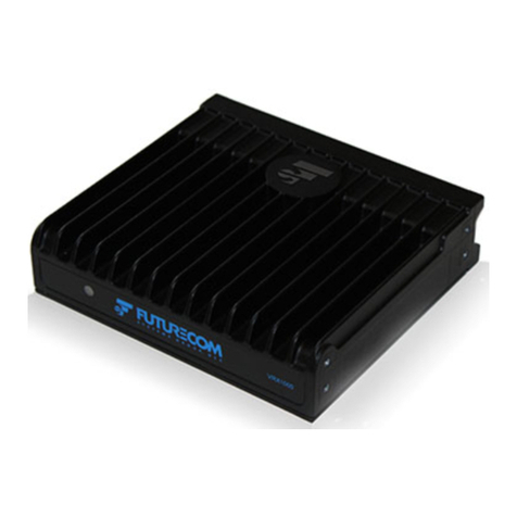
Futurecom VRX1000 User manual

Futurecom Systems Group, ULC
VRX1000 Installation Guide

8M087X03 R0
VRX1000 Installation Guide
Nov 2020 Page 2
Notes

8M087X03 R0
VRX1000 Installation Guide
Nov 2020 Page 3
Related Publications
Publication
Number
Description
8A087X02
VRX1000 User’s Guide
8A087X01
VRX1000 Ordering Guide
8K087X02
VRX1000 Functional Description
Manual Revisions
Rev #
Date
Notes & References
0
November 23, 2020
Original Release

8M087X03 R0
VRX1000 Installation Guide
Nov 2020 Page 4
Foreword
Futurecom Vehicular Repeater (VR) is designed to be seamlessly interfaced to:
•Remote Mount APX Series MSU with or without control head
When the VR is interfaced to a Remote Mount Motorola APX Mobile Radio, the complete
equipment package is referred to as Digital Vehicular Repeater System (DVRS). APX
Mobile Radios operating through a VR, utilizing the enhanced DVR digital feature set
require option GA00631.
APX & APXNext Portable Radios operating through a VR, utilizing the enhanced DVR
digital feature set require subscriber option QA00631.
See https://futurecom.com/upl/downloads/resources/support-resources/firmware-
compatibility-chart.pdf about version requirements for compatible Mobile and Portable
radios.
For details on the APX series Mobile or Portable Radios operation, please refer to the
applicable Manuals available from Motorola.
For details on the DVRS Operation, please refer to the VR User’s Guides 8A093X01

8M087X03 R0
VRX1000 Installation Guide
Nov 2020 Page 5
Document Copyrights
No part of this manual may be reproduced, distributed or transmitted in any form or by
any means, for any purpose without written permission of Futurecom.
Disclaimer
The information in this document is carefully examined and is believed to be entirely
reliable. However, no responsibility is assumed for inaccuracies. Futurecom Systems
Group, ULC. reserves the right to make changes to any products herein to improve
reliability, function or design. Futurecom does not assume any liability arising out of the
application or use of any product or circuit described herein.
Trademarks
Futurecom, PDR8000, the Futurecom Logo and the Stylized FC logo are registered
trademarks of Futurecom Systems Group, ULC. All other trademarks are the property of
their respective owner. © 2020 Futurecom Systems Group, ULC. All rights reserved.
MOTOROLA, MOTO, MOTOROLA SOLUTIONS and the Stylized M logo are
trademarks or registered trademarks of Motorola Trademark Holdings, LLC and are
used under license. All other trademarks are the property of their respective owners.

8M087X03 R0
VRX1000 Installation Guide
Nov 2020 Page 6
Commercial Warranty
Futurecom Systems Group, ULC. warrants to the original purchaser all standard
products sold by Futurecom Systems Group, ULC to be free of defects in material and
workmanship for one (1) year from the date of shipment from Futurecom Systems Group,
ULC.
Futurecom’s warranty hereunder DOES NOT cover the following:
(i) Defects or damage resulting from use of the product in other than its normal
and customary manner.
(ii) Defects or damage from improper installation, testing, operation,
or maintenance.
(iii) Defects or damage due to alterations, modifications or adjustments carried
out by the Buyer without Futurecom’s explicit approval.
(iv) Defects or damage from misuse, accident, water orneglect.
(v) Freight costs to the repair depot.
(vi) Scratches or other cosmetic damage to the product surfaces that does not
affect the operation of the product.
(vii) Normal wear and tear.
The warranty set forth herein is conditioned upon proper storage, installation, use and
maintenance in accordance with applicable written recommendation of Futurecom. The
warranty furnished hereunder does not extend to damage to items purchased hereunder
resulting in whole or in part from the use of components, accessories, parts of supplies
not furnished by Futurecom Systems Group, ULC.
Futurecom’s sole obligation shall be to repair or replace, at Futurecom’s option, any
defective component or item and pay transportation expenses for such replacement at no
charge to Buyer who shall provide labor for the removal of the defective component or
item and installation of its replacement at no charge to Futurecom. Buyer shall bear all
risk of loss or damage to returned goods while in transit. In the event no defect or breach
of warranty is discovered by Futurecom upon receipt of any returned item, the item will be
returned to Buyer at Buyer’s expense and Buyer will reimburse Futurecom for the
transportation charges, labor and associated charges incurred in testing the allegedly
defective item.
Except as expressly provided herein, Futurecom makes no warranty of any kind,
expressed or implied, with respect to any goods, parts and service provided by Futurecom
including, but not limited to, the implied warranties or merchantability and fitness for a
particular purpose. The sole and exclusive remedy for breach of any warranty is limited to
the remedies provided in the paragraph above. Futurecom shall not in any event be liable
for any other damages arising out of or in connection with furnishing of goods, parts or
service hereunder, or the performance, use of, or inability to use any goods, parts or
service, or otherwise, whether based on contract, tort or any other legaltheory.
To exercise this warranty, please contact Futurecom’s Administration Department in
Concord, Ontario, Canada at 1-800 701 9180 to obtain a return material authorization
(RMA) and shipping instructions. No product will be accepted for return without an RMA.
The repair of a product by Futurecom pursuant to this warranty is warranted for the
balance of the original warranty period, or at least 90 days from date of shipment to Buyer
of the repaired product.
If Extended Warranty is required, it must be purchased either at the time of original
purchase or while the unit is under the standard first year warranty coverage.

8M087X03 R0
VRX1000 Installation Guide
Nov 2020 Page 7
Contents
Related Publications..........................................................................................................................3
Manual Revisions...............................................................................................................................3
Foreword .............................................................................................................................................4
Document Copyrights........................................................................................................................5
Disclaimer ...........................................................................................................................................5
Trademarks .........................................................................................................................................5
Commercial Warranty ........................................................................................................................6
Contents..............................................................................................................................................7
List of Tables ......................................................................................................................................9
List of Figures.....................................................................................................................................9
Notations Used in This Manual.......................................................................................................10
Declaration of Conformity ...............................................................................................................11
FCC LABELS:...................................................................................................................................................11
RF Energy Exposure Compliance, Awareness and Control Information and Operational
Instructions.......................................................................................................................................12
RF Exposure Label .........................................................................................................................................13
FCC Label.......................................................................................................................................................13
Installation Requirements for Compliance with Radio Frequency (RF) Energy Exposure
Safety Standards ..............................................................................................................................14
INTRODUCTION...........................................................................................................................15
IDENTIFYING YOUR VRX1000 MODEL ................................................................................17
Frequency Band of Operation.........................................................................................................17
Cross-Band .......................................................................................................................................17
Cross Band VRX1000 Dimensions..................................................................................................................18
In-Band ..............................................................................................................................................19
In-Band VRX1000 Dimensions.......................................................................................................................20
VRX1000 INSTALLATION BASICS..........................................................................................21
Planning the Installation..................................................................................................................21

8M087X03 R0
VRX1000 Installation Guide
Nov 2020 Page 8
Installation Tools Required .............................................................................................................21
Mounting the VRX1000 ....................................................................................................................22
Cross-Band VRX1000 Mounting ....................................................................................................................22
In-Band VRX1000 Mounting..........................................................................................................................23
Mounting the Mobile Radio .............................................................................................................24
Connecting the VRX1000 Cables....................................................................................................25
Power Cable ..................................................................................................................................................26
RF Cables.......................................................................................................................................................27
Control Cables...............................................................................................................................................27
VRX1000 Auxiliary Cable ...............................................................................................................................30
AVRA .................................................................................................................................................31
Status Lights.....................................................................................................................................31
External Alarm..................................................................................................................................31
VRX1000 Antenna Installation.........................................................................................................32
APPENDIX 1–VRX1000 SPECIFICATIONS ..........................................................................34
APPENDIX 2 –ACCESSORIES ...................................................................................................36
VRX1000 Antennas –Vehicular Mount...........................................................................................36
Spare Cables.....................................................................................................................................36
CONTACT INFORMATION.........................................................................................................37
INDEX..............................................................................................................................................38
GLOSSARY......................................................................................................................................39

8M087X03 R0
VRX1000 Installation Guide
Nov 2020 Page 9
List of Tables
Table 1 Minimum Lateral Distance from Antenna –VRX1000 ..........................................................13
Table 2 VRX1000 vs Infrastructure Compatibility (Voice and Signaling)...........................................15
Table 3 VRX1000 RF Cables.............................................................................................................27
Table 4 VRX1000 Control Cable Types.............................................................................................27
List of Figures
Figure 1 Cross-Band VRX1000 - Conceptual Diagram......................................................................17
Figure 2 Cross-Band VRX1000 - Dimensions mm / [in].....................................................................18
Figure 3 In-Band VRX1000 - Conceptual Diagram............................................................................19
Figure 4 In-Band VRX1000 –Flat Mount Dimensions mm / [in]........................................................20
Figure 5 Cross-Band VRX1000 Mounting Details..............................................................................22
Figure 6 In-Band VRX1000 - Flat Mount Details................................................................................23
Figure 7 In-Band VRX1000 Stacked Mount Details...........................................................................23
Figure 8 VRX1000 Connectors ..........................................................................................................25
Figure 9 VRX1000 Standard Control Cable (PN 7W087X07)............................................................28
Figure 10 VRX1000 Y-Control Cable with AUX Extension (PN 7W087X08).....................................28
Figure 11 MSU Side DB25 Pinout (All Control Cables) .....................................................................29
Figure 12 Auxiliary Options - DB15 Pinout.........................................................................................30

8M087X03 R0
VRX1000 Installation Guide
Nov 2020 Page 10
Notations Used in This Manual
The following notations are used throughout this document:
NOTE:
A clarifying statement that expands on the text that follows.
IMPORTANT!
An important statement that should be considered and / or implemented in order
to achieve adequate equipment operation.
ATTENTION!
An instruction that must be followed to insure compliance with the appropriate
standards or proper equipment operations.

8M087X03 R0
VRX1000 Installation Guide
Nov 2020 Page 11
Declaration of Conformity
This equipment has been tested and found to comply with the limits for a Class A digital
device, pursuant to Part 15 of the FCC Rules. These limits are designed to provide
reasonable protection against harmful interference when the equipment is operated in a
commercial environment. This equipment generates, uses, and can radiate radio
frequency energy and, if not installed and used in accordance with the instruction manual,
may cause harmful interference to radio communications. However, there is no guarantee
that interference will not occur in a particular installation.
FCC LABELS:
This device complies with Part 15 of the FCC Rules. Operation is subject to the
following two conditions:
(1) This device may not cause harmful
interference. and
(2) This device must accept any interference received,including
interference that may cause undesiredoperation.
FCC SECTION 15.105 INFORMATION TO THE USER:
NOTE: This equipment has been tested and found to comply with the limits for
a Class B digital device, pursuant to Part 15 of the FCC Rules. These limits are
designed to provide reasonable protection against harmful interference in a
residential installation. This equipment generates, uses and can radiate radio
frequency energy and, if not installed and used in accordance with the
instructions, may cause harmful interference to radio communications.
However, there is no guarantee that interference will not occur in a particular
installation. If this equipment does cause harmful interference to radio or
television reception, which can be determined by turning the equipment off and
on, the user is encouraged to try to correct the interference by one or more of
the following measures:
-- Reorient or relocate the receiving antenna.
-- Increase the separation between the equipment and receiver.
-- Connect the equipment into an outlet on a circuit different from that to which
the receiver is connected.
-- Consult the dealer or an experienced radio/TV technician for help.

8M087X03 R0
VRX1000 Installation Guide
Nov 2020 Page 12
RF Energy Exposure Compliance, Awareness and Control Information
and Operational Instructions
USA Users: Do not use the VRX1000 in the frequency band 406.0 –406.1MHz. This
frequency band is reserved for distress beacons.
ATTENTION!
Changes or modifications not expressly approved by Futurecom Systems Group,
ULC. could void the User’s authority to operate the equipment. To satisfy FCC/IC
RF exposure requirements for mobile transmitting devices, the minimum separation
distances specified in Table 1 should be maintained. To ensure compliance,
operations at closer than this distance is not allowed.
ATTENTION!
Futurecom requires the P25 VRX1000 operator to ensure FCC Requirements for
Radio Frequency Exposure are met. The minimum distance between all possible
personnel and the body of the VRX1000 equipped vehicle is specified in the “RF
Safety” booklet. Failure to observe the Maximum Permissible Exposure (MPE)
distance exclusion area around the antenna may expose persons within this area
to RF energy above the FCC exposure limit for bystanders (general population). It
is the responsibility of the repeater operator to ensure MPE limits are observed at
all times during repeater transmissions. The repeater operator must ensure at all
times that no person comes within MPE distance from the vehicle body.
ATTENTION!
This radio is intended for use in occupational / controlled conditions, where users
have full knowledge of their exposure and can exercise control over their exposure
to meet FCC limits. This radio device is NOT authorized for general population,
consumer, or any other use.
It is the responsibilityof the VRX1000 Operator to ensure that Maximum Permissible
Exposure (MPE) limits are observed at all times during repeater transmissions. If
this vehicular repeater is used in combination with a separate mobile radio
transmitter, the Repeater operator must ensure at all times that no person comes
within the MPE distance from the vehicle body to ensure compliance with the
FCC’s/IC’s RF energy exposure limits for the general population.
The minimum lateral distance between all possible personnel and the body of the
VRX1000 equipped vehicle must be as specified in
Table 1.
Failure to observe theMPE distance exclusion area around the antenna mayexpose
persons within this area to RF energy above the FCC exposure limit for bystanders
(general population).

8M087X03 R0
VRX1000 Installation Guide
Nov 2020 Page 13
VRX1000 (3W)
Minimum Lateral Distance from Antenna
VHF
67.0cm (26.4 inches) (up to 100% Tx duty cycle)
UHF 380-512MHz
40.0cm (15.75 inches) (up to 100% Tx duty cycle)
700MHz
28.3cm (11.1 inches) (up to 100% Tx duty cycle)
800MHz
26.8cm (10.6 inches) (up to 100% Tx duty cycle)
Table 1 Minimum Lateral Distance from Antenna –VRX1000
50% Tx duty cycle is defined as Push To Talk (PTT), 50% Talk - 50%
Listen. 100% Tx duty cycle is defined as Push To Talk (PTT), 100% Talk
IMPORTANT
The nominal allowed gain of the λ/4 Omni-directional antenna for the VRX1000 is
Unity (0 dBd).
RF Exposure Label
The RF Exposure Label should be affixed in the vehicle beside the mobile radio
control head. The label should be in the direct view of the Repeater operator. The
label is supplied with the VRX1000.
FCC Label

8M087X03 R0
VRX1000 Installation Guide
Nov 2020 Page 14
Installation Requirements for Compliance with Radio Frequency (RF)
Energy Exposure Safety Standards
ATTENTION!
To ensure compliance with RF Energy Safety Standards:
▪Install only Futurecom / Motorola Solutions approved antennas and accessories and
set conducted power into the VRX1000 antenna equal to or lower than the approved
power levels –refer to Table 1.

8M087X03 R0
VRX1000 Installation Guide
Nov 2020 Page 15
Introduction
The VRX1000 is a simplex radio coverage extender, which is interfaced to acompatible
remote mount Motorola Solutions Mobile Radio and enables Portable Subscriber Units
(PSU) to be used in areas where only Mobile Subscriber Unit (MSU) coverage is
available and PSU coverage is either intermittent or completely absent.
Installed in the trunk of a car, fire truck, armored vehicle, ambulance, the VRX1000
extends radio communications to the PSU users who are outside of the vehicle, inside
a nearby building or in any marginal portable radio coverage areas. The VRX1000
extends voice (analog or digital, clear or encrypted) communications and supports key
Trunking system features. The VRX1000 can be configured to provide various
advanced options to the users.
The Vehicular Radio Extender (VRX1000) is designed to be seamlessly interfaced to
the following Motorola Solutions Mobile Radios:
Mobile Radio Model
Firmware Requirements
Notes
APX4500
R21.40.00
Requires option GA00631
APX6500
R21.40.00
APX7500
R21.40.00
APX8500
R21.40.00
NOTE:
Mobile Radio must be configured as Remote Mount in order to be compatible with the
VRX1000.
Table 2 below provides information on the VRX1000 infrastructure compatibility options.
FIXED NETWORK TYPE / MOBILE RADIO MODE
Portable
Radio Type
/ Mode
Conventional
Analog incl.
Mixed Receive
Conventional
P25 incl.
Mixed Receive
3600 Analog /
Digital
Trunking
9600 P25
Trunking
FDMA
9600 P25
Trunking
TDMA
Conventional
Analog
YES
A
YES
A/M
YES
A
YES
A/M
YES
A
Generic P25
Conventional
NO
YES
D/M/FA
NO
YES
D/M/FA
NO
P25
Conventional
‘DVRS
Enabled’
YES
FA/FA-All
YES
D/FA/FA-
All/M
YES
FA/FA-All
YES
D/FA/FA-
All/M
YES
D/FA/FA-
All/M
Table 2 VRX1000 vs Infrastructure Compatibility (Voice and Signaling)
VRX1000 Channel Types:
A = Analog, D = Digital, M = Mixed, FA = Forced Analog, FA-All=Forced Analog
All (See Part II of this manual)

8M087X03 R0
VRX1000 Installation Guide
Nov 2020 Page 16

8M087X03 R0
VRX1000 Installation Guide
Nov 2020 Page 17
Identifying Your VRX1000 Model
Frequency Band of Operation
Depending on the frequency band of operation of the APX Mobile Subscriber Unit
(MSU) and VRX1000, the VRX1000 models are classified as follows:
•In-Band –when the MSU and VRX1000 operate in the same frequencyband.
•Cross-Band –when the MSU and VRX1000 operate in two different
frequency bands.
Cross-Band
Cross-Band VRX1000 models do not include any filters on the MSU side since the
MSU and VRX1000 are not intended to simultaneously operate in the same
frequency band. In single band MSU configurations the MSU and VRX1000
operate in different frequency bands.
In dual band MSU configuration either the MSU & VRX1000 operate in 3 different
frequency bands or oneof the MSU frequency bands is locked out when VRX1000
operation is enabled as shown on Figure 1.
Figure 1 Cross-Band VRX1000 - Conceptual Diagram

8M087X03 R0
VRX1000 Installation Guide
Nov 2020 Page 18
Cross Band VRX1000 Dimensions
180 [7.10] x 160 [6.30] x 63 [2.48] mm [in]
Figure 2 Cross-Band VRX1000 - Dimensions mm / [in]

8M087X03 R0
VRX1000 Installation Guide
Nov 2020 Page 19
In-Band
The in-band VRX1000 models are equipped with two sets of filters, which are
required in order to ensure interference-free operation when both the MSU and
VRX1000 are transmitting and receiving simultaneously in the same frequency
band. The VRX1000 filter provides 40 dB isolation on the Mobile radio transmit /
receive frequencies. The filter installed at the output of the MSU is designed to
provide 40dB isolation on the VRX1000 TX/RX Frequency Range.
NOTE:
The VRX1000 and MSU require two or three (in the case of dual band MSU) separate
antennas.
Figure 3 In-Band VRX1000 - Conceptual Diagram
IMPORTANT!
The above filter isolation must be complemented by 30dB minimum antenna
isolation (between the VRX1000 and Mobile Radio antennas) in order to ensure
interference-free operation. It is recommended that the MSU in-band antenna is
mounted on the roof top of the vehicle while the VRX1000 antenna is mounted on
the trunk. Each VRX1000 is shipped equipped with custom filters tuned to the
specified frequency bands –note the frequency range specified on the filter labels.
Programming the VRX1000 / MSU radio to operate on frequencies outside of the
original specified bands may result in intermittent or complete loss of
communications. Frequency changes may require filter retuning orreplacement.
NOTE:
The In-Band filters connected to the APX MSU have typical insertion loss of 1.5dB.

8M087X03 R0
VRX1000 Installation Guide
Nov 2020 Page 20
In-Band VRX1000 Dimensions
Figure 4 In-Band VRX1000 –Flat Mount Dimensions mm / [in]
VRX1000
180 [6.30] X 160 [6.30] X 63 [2.48]
7D087X01-XX VRX1000 In-Band Filter
253.2 [10.0] X 152.4 [6.00] X 55.6 [2.20]
7N087X01-XX MSU In-Band Filter
253.2 [10.0] X 152.4 [6.00] X 55.6 [2.20]
NOTE:
The in-band filters are also available as stacked mount.
Other manuals for VRX1000
8
Table of contents
Other Futurecom Extender manuals