manuals.online logo
Brands
  1. Home
  2. •
  3. Brands
  4. •
  5. FW Murphy
  6. •
  7. Controllers
  8. •
  9. FW Murphy TTD Series User manual

FW Murphy TTD Series User manual

sect. 50 00-02-1010
rev. 2021/07/21
Fender washer
with star nut
on top stud
(option)
5/16” star nuts on three studs
How to Replace LCDT with TTD
In this LCDT replacement conguration, the TTD will not carry a NEMA 4 rating due to the mounting stud removal mentioned in
the installation section below.
Hazardous Area Classification
The TTD has CSA Class I, Division 2, Groups B, C and D approval. This differs from LCDT which has CSA Class I, Division 1,
Group D approval. Consult with your AHJ for a review of classication for the area where the LCDT is installed for verication
that it may t into Class I, Division 2 classication.
Certification
Please read the Installation & Operation manual for the TTD. This will familiarize you with the new features and congurability
available in the TTD.
LCDT mounting holes circled
Catalog Subsection for Table of Contents
95026 Product Name for Catalog Table of Contents
Remove the
circled TTD
mounting
studs.
Installation
1. The TTD-2 model (part # 50700601) offers exact drop-in
replacement option for both models of LCDT-NO and
LCDT-NC.
a. Systems powered by 12- or 24-VDC (battery powered)
or CD negative ground ignition are fully compatible.
b. Systems powered by 120-VAC line voltage will require
a 24-VDC power supply installed to power the TTD.
c. CD positive ground ignition systems are not supported
by TTD.
2. This guideline is for typical installations with fuel valve,
ignition and power input connection changes and are
meant to supplement the TTD installation diagram 50-08-
0718.
a. Refer to the drawing in the TTD Installation &
Operation manual for clarication on your specic
installation.
b. To nd all information about TTD features and options
as well as the downloadable installation & operations
manual, go to https://www.fwmurphy.com/products/
controllers/ttd.
3. Mount the TTD head.
a. Only three (3) of the TTD mounting studs are used to
mount to the original LCDT mounting holes.
b. On the TTD, remove the mounting studs (5) circled
below. Use pliers to turn them counterclockwise to
unscrew from the bezel. Removing studs in this matter
will not affect warranty of the TTD.
c. Align the TTD studs with the 2 bottom holes and insert
into the LCDT opening. They will t into the old holes.
The top center stud will be on the top edge of the
cutout.
d. Install a star nut on the bottom studs rst, then on
the top center stud. The top center nut will catch
the edge of the sub panel plate as shown below. For
vibration or stability concerns a 5/32” x 7/8” stainless
fender washer is recommended.
e. Tighten the three 5/16” star nuts to 9 in. lbs. (1 Nm).
Normally closed sensor wiring to TTD (typical)
b. For Normally Closed: Remove the LCDT-TB-NO from
the panel.
i. Two wire normally closed sensors will be wired to
the matching sensor channel terminals on the TTD.
ii. Remove the factory-installed jumper installed
across matching TTD terminals and insert one wire
into each of the matching terminals on the TTD.
5. Connect the power supply wiring.
a. The LCDT power supply will not be used, but the explosion-proof
enclosure may be used as a junction box to extend wiring to the TTD.
b. Extend the wires located inside the power supply enclosure and re-route
up to the TTD mounted inside the enclosure.
LCDT-PS-120/24/12
4. Connect the Sensor Wiring for NO or NC.
a. For Normally Open: Remove the LCDT-TB-NO from
the panel.
Normally open sensor wiring to TTD (typical)
i. Single wire normally open, (ground to shutdown)
sensors will be wired to the matching sensor
channel on the TTD.
ii. Leave the factory-installed jumper installed across
matching TTD terminals, and terminate the sensor
wire to either of the matching terminals on the
TTD.
c. Follow the wiring changes as applicable, LCDT-PS-CD-N CD ignition
powered wiring changes to new TTD.
CD Ignition Powered Wiring Changes ( LCDT-PS-CD-N to New TTD)
LCDT
Terminal Description New TTD
Terminal
1 (IGN) Ignition (power) IGN (IGN SD)
2 (FV+) Fuel valve coil + FV+
3 (FV-) Fuel valve coil - FV-
4 (GND) Chassis ground GND
5 (NO) Shutdown Alarm Relay Normally Open (to
run) ALR***
6 (Com) Shutdown Alarm Relay Common
7 (NC) Shutdown Alarm Relay Normally Closed (to
run)
***TTD does not have a dry contact for the shutdown alarm but will ground the
ALR terminal through internal solid state FET when a shut-down alarm occurs.
d. Follow the wiring changes as applicable, LCDT-PS-120/24/12 DC powered wiring changes to new TTD.
DC Powered Wiring Changes ( LCDT-PS-120/24/12 to New TTD)
LCDT Terminal Description New TTD
Terminal
1 (C) Ignition relay common Not available
2 (NO) Ignition relay normally open IGN*
3 (C) Fuel relay common FV-**
4 (NO) Fuel relay normally open FV+**
5 (C1) Shutdown Alarm Relay Normally Open (to run) ALR***
6 (NC1) Shutdown Alarm Relay Common
7 (NO1) Shutdown Alarm Relay Normally Closed (to run) ALR***
8 (+) DC+ power input DC
9 (-) DC- power input GND
10 (GRD) Ground GND
11 (N) 120 VAC power input Not available
12 (H) 120 VAC power input Not available
*TTD does not have a dry contact for ignition but will ground the IGN terminal to stop the equipment through
internal solid state FET. Behavior of the IGN terminal is congurable for open to GND to run or closed to GND
to run.
** TTD does not have a dry contact for fuel valve. Verify Fuel valve wiring against wiring guidelines shown in
TTD Installation & Operation Manual. Behavior of the FV- terminal is congurable for open to GND to run or
closed to GND to run.
***TTD does not have a dry contact for the shutdown alarm but will ground the ALR terminal through internal
solid state FET when a shut-down alarm occurs.
e. Follow the wiring diagrams for the TTD as needed.
Template Settings B1
Lockout
B2
Lockout Class A Class C Over-
speed
Remote
Reset
Remote
Lockout
Local
ESD
Remote
ESD
0Only when SETUP 2 is set to 0 can individual channels be set in SETUP 3
1 TTD Default N/A N/A (1-46) N/A N/A (45*) (46*) (47)**) (45)**)
2 TTD MARK II 8 (16-23) N/A 32 (1-15, 24-40) 4 (41-44) N/A (45*) (46*) (47)**) (45)**)
3 TTD MARK III 9 (1-9) N/A 31 (10-30, 32-40, 48) 4 (41-44) N/A (45*) (46*) (47)**) (45)**)
4 TTD MARK IV,
LCDT
15 (1-15) N/A 25 (16-40) N/A N/A (45*) (46*) (47)**) (45)**)
5 TTD MARK IV,
LCDT +
15 (1-15) N/A 25 (16-40) 4 (41-44) N/A (45*) (46*) (47)**) (45)**)
6 TTD Generic 16 (1-16) 4 (17-20) 20 (21-40) 4 (41-44) N/A (45*) (46*) (47)**) (45)**)
20 DD-20 Altronic 8 (10-17) N/A 11 (20-27, 30-32) N/A N/A (45*) (46*) N/A N/A
40 DD-40 Altronic 16 (10-
17, 0-27)
N/A 21 (30-37, 40-47, 1-8) N/A N/A (45*) (46*) N/A N/A
6. Post installation steps TTD setup checks.
a. To setup the desired startup B1 lockout time, press and hold Setup/Enter key to access the Timer (Setup #1) menu.
This menu also has the ignition ground delay to burn unspent fuel. If eyelets E1 and E2 are missing in the LCDT power
supply, then there should be a 3-5 second time entered for Timer 4 in the menu for Ignition Ground delay.
b. To emulate the input channel setup map of the LCDT, press and hold Setup/Enter key to access the Sensor Mode
(Setup #2) menu and select that option as 4 or 5 as needed for the application.
c. Use Setup #5 to preset the package’s run-hourmeter.
d. Use Setup #A to set the behavior of the Ignition and Fuel Valve outputs. Mode 0 will emulate the behavior of the Ignition
and Fuel valve operation of open to ground to run, closed to ground to stop like the LCDT. Mode 0 will emulate the
behavior of the Ignition and Fuel valve operation of open to ground to run, closed to ground to stop like the LCDT.

Other manuals for TTD Series

1

This manual suits for next models

4

Other FW Murphy Controllers manuals

FW Murphy Centurion C5 User manual

FW Murphy

FW Murphy Centurion C5 User manual

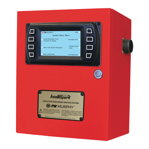
FW Murphy IntelliSpark User manual

FW Murphy

FW Murphy IntelliSpark User manual

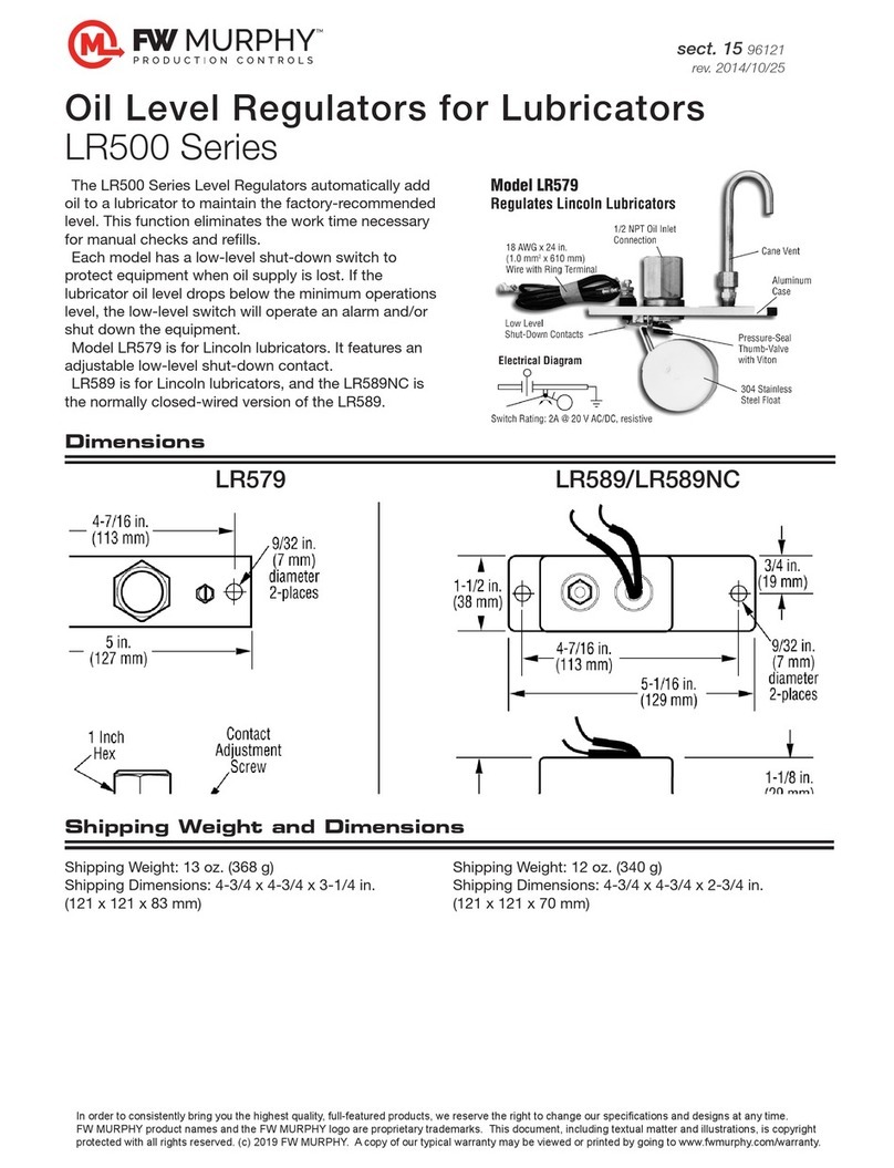
FW Murphy LR579 User manual

FW Murphy

FW Murphy LR579 User manual

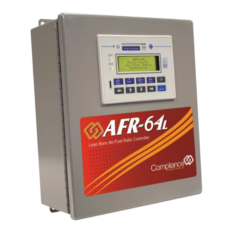
FW Murphy AFR-64L User manual

FW Murphy

FW Murphy AFR-64L User manual

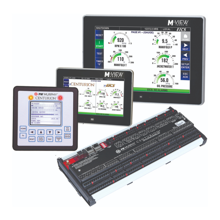
FW Murphy Centurion C5 M-VIEW Touch Series User manual

FW Murphy

FW Murphy Centurion C5 M-VIEW Touch Series User manual

Popular Controllers manuals by other brands

MOTECK ID10 manual

MOTECK

MOTECK ID10 manual

Enertronica Santerno ASAC-1 Series manual

Enertronica Santerno

Enertronica Santerno ASAC-1 Series manual

Imit FIRE/503 WATER-N instructions

Imit

Imit FIRE/503 WATER-N instructions

Vicon v1500x sccs 1 Installation & operation manual

Vicon

Vicon v1500x sccs 1 Installation & operation manual

Norac UC4+ installation manual

Norac

Norac UC4+ installation manual

Neousys Technology POC-700 Series user manual

Neousys Technology

Neousys Technology POC-700 Series user manual

Shimaden SR90 Series instruction manual

Shimaden

Shimaden SR90 Series instruction manual

Explore Scientific PMC-Eight ESOGT-01B Programmer's reference

Explore Scientific

Explore Scientific PMC-Eight ESOGT-01B Programmer's reference

Creative Conners Stagehand Pro 3 Reference manual

Creative Conners

Creative Conners Stagehand Pro 3 Reference manual

Videotec DTRX1 operating instructions

Videotec

Videotec DTRX1 operating instructions

Shure AD600 user manual

Shure

Shure AD600 user manual

fakro ZWK1 user manual

fakro

fakro ZWK1 user manual

Mitsubishi MELSEC-L Series user manual

Mitsubishi

Mitsubishi MELSEC-L Series user manual

ABB ControlMaster CM15 Commissioning instructions

ABB

ABB ControlMaster CM15 Commissioning instructions

Emerson Bristol ControlWave PAC Technical specifications

Emerson

Emerson Bristol ControlWave PAC Technical specifications

sauter ASV 52 Series Maintenance manual

sauter

sauter ASV 52 Series Maintenance manual

THORLABS FPC020 user guide

THORLABS

THORLABS FPC020 user guide

Allen-Bradley micrologix 1500 user manual

Allen-Bradley

Allen-Bradley micrologix 1500 user manual

manuals.online logo
manuals.online logoBrands
  • About & Mission
  • Contact us
  • Privacy Policy
  • Terms and Conditions

Copyright 2025 Manuals.Online. All Rights Reserved.