FWB multiBALL User manual

Setup Guide
Fun With Balls GmbH

What’s inside the box
Frame (x10) Light Bar (x10) Cover (x10) Sensor Cable (x4) Light Bar Bolt M2 (x40) Cover Bolt M6 (x40)
Speaker Box with Processing Unit

Recommended Equipment
Rolling Scaffolding Spirit Level (Impact) Drill Allen® Key Set

Step 1
Arrange the Frames
FR1
FR10
FR9
FR4 FR5
FR2
FR3
FR8
FR7
FR6
Description
Sticker
MB Frame Top Left
FR1
MB Frame Top Middle
FR2
MB Frame Top Right
FR3
MB Frame Rightside Up
FR4
MB Frame Rightside Down
FR5
MB Frame Bottom Right
FR6
MB Frame Bottom Middle
FR7
MB Frame Bottom Left
FR8
MB Frame Leftside Down
FR9
MB Frame Leftside Up
FR10

Step 2
Mount Frames
Max. 5cm
1
2
3
Mount profiles to the wall
1 bottom - fix all screws and we advice to keep the distance of !
about 5cm only or less from the floor for the ease of handling.!
2 sides - only fix the top screw for each profile to hold it in place !
3 top - try if the distance to the sides is correct and the top fits!
- then fix all top screws and last the remaining screws for the sides
Please make sure all profiles are perfectly horizontal/vertical
Bolts, dowels and washers are not included, due to different
wall types. Please organize them yourself. There are 20 holes
with a diameter of 8mm for the attachment.

Step 3
Mount the Light bars
Red surface of the bars facing towards the inside!
Cables towards the outside of the frame
Do not over-tighten the bolts!
Use small black bolts provided, using additional bolt
adhesive is recommended
Red
Surface
Cables
LS1
LS3
LS4
LS5
LS2
LR1
LR2
LR3
LR4
LR5
Description
Sticker
MB Lightbar Top Left
LS1
MB Lightbar Top Centre
LS2
MB Lightbar Top Right
LS3
MB Lightbar Leftside Up
LS4
MB Lightbar Leftside Down
LS5
MB Lightbar Bottom Left
LR1
MB Lightbar Bottom Centre
LR2
MB Lightbar Bottom Right
LR3
MB Lightbar Rightside Up
LR4
MB Lightbar Rightside Down
LR5

Step 4
Open multiBALL Console
Remove the 8 small bolts holding the cover.
Carefully lift up the cover and make sure you disconnect the
speaker cables!
2x
2x
2x
2x

Step 5
Mount multiBALL Console
ca. 5cm
Use this step to connect the LAN, HDMI and Power Cables.

Step 6
Connect sensor cables
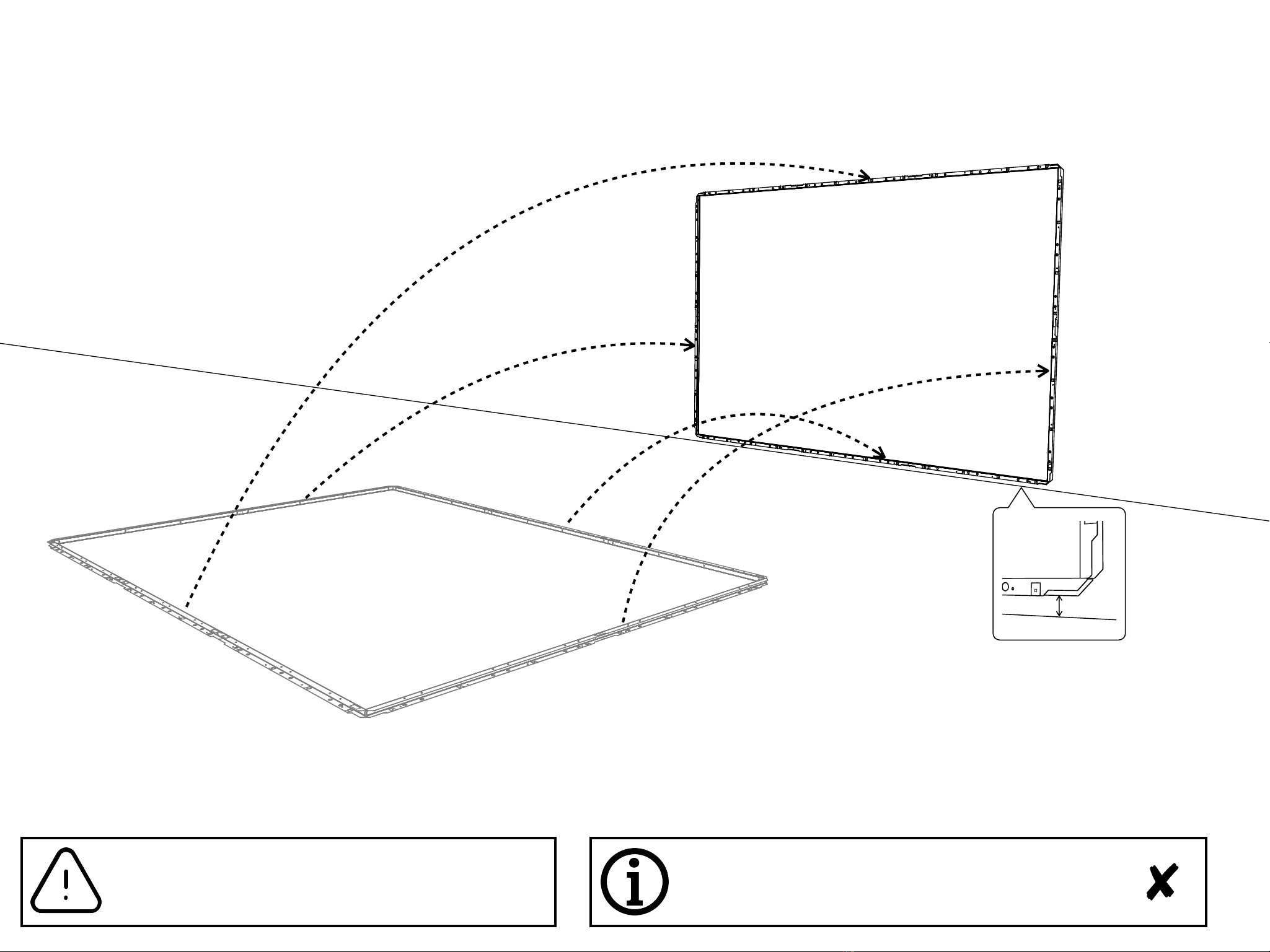
Connect the light bars with each other. The open and labeled
plugs have to be connected to the sensor cables.
Use connection diagram!
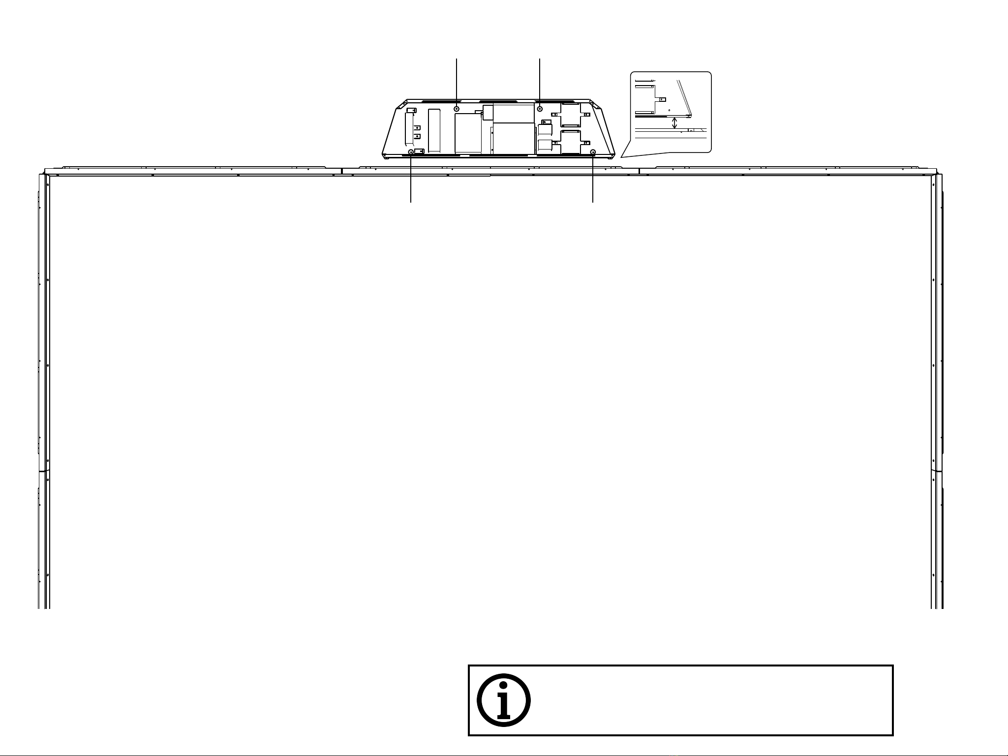
Put all the cables into the Base Profiles. Any spare cable can
be arranged in the top Base Profile. To prevent the cables
from falling back out, bend the square flaps with a screw
driver to hold the cables in place.
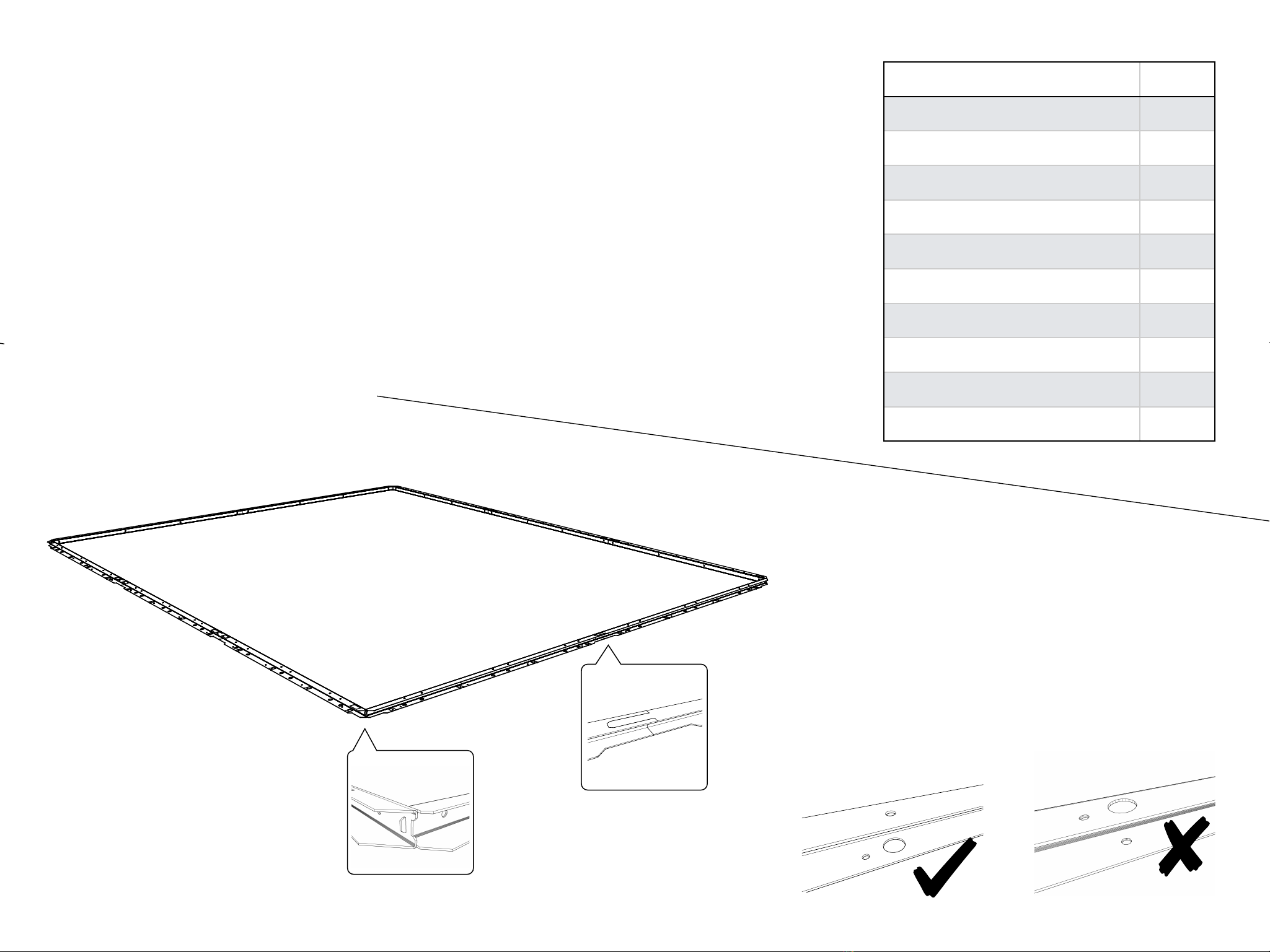
The plugs are equipped with a guide to ensure correct
connection. Make sure to gently find the guide before
pushing the plugs together and screwing them tight!
!
TXZS1 TXES1TXZS2
TXZS3
TXES2
Lvx X Lvx Y
TOP
Computer
Power
Power
CAN/RS232
COM 1 HDMI
Projector
LAN
HDMIHDMI
Power
Power Line
RXZS3
RXES2
RXZS1 RXZS2 RXES1
Calibration of the light grid:
Before the first power on after mounting the light bars to their final position put switch 3
(the array of tiny switches) up on both of the LVX-devices. Then Power on the System and
check that the green LED below the orange LED is lit. When interrupting a beam the green
light should go off. Check for both Axis X and Y. Then put down the switch 3 (to off). Now
the light grid is ready to use
Multiball setup and connection plan
SEA
EMA
B.1-B.8 h
LS1
LS2
LS3
LS4
LS5
LR1
LR2
LR3
LR4
LR5
MB X
MB Y
SY
RY
SX
RX
RX
SX
RY
SY

Step 7
Calibrate LVX
Touching the wall should now make two more green LEDs flash up near to the big power connector plug
1. Power ON Computer!
2. Power OFF the LVX’s (disconnect plug)!
3. Flip switch #3 on both LVX with a small screw driver!
4. Power ON the LVX´s (re-connect plug)!
5. Check if both green and orange lights on the LVX´s are ON.!
6. Touch the wall between the light bars, the green light should go OFF touching the wall!
7. After the touch the green light should go ON again!
8. Power OFF the LVX´s (disconnect plug) after checking!
9. Pull switch 3 back again in row with the others!
10.Power ON the LVX’s!

Step 8
Mount Covers
Carefully slide on the covers and avoid pinching or bending
the sensor cables!
If using an electric drill, make sure not to damage the white
surface of the wall!
Labels match the ones on the Light Bars.
Use silver bolts provided.
Once covers are on, repeat Step 7 „Calibrate LVX“
CV1
CV3
CV10
CV9
CV2
CV8
CV7
CV6
CV4
CV5
Description
Sticker
MB Cover Top Left
CV1
MB Cover Top Centre
CV2
MB Cover Top Right
CV3
MB Cover Rightside Up
CV4
MB Cover Rightside Down
CV5
MB Cover Bottom Right
CV6
MB Cover Bottom Centre
CV7
MB Cover Bottom Left
CV8
MB Cover Leftside Down
CV9
MB Cover Lefttside Up
CV10

Step 9
Adjust Projector
To get a picture, always make sure you power on the
projector first and then the multiBALL system.
If the game does not fit in the visible picture, get in touch
with us so we can remotely change the settings
Using „Shift“ and „Corner Correction“ on your projector,
align the picture so it perfectly fits into the frame.
Now its time to test the system for the first time. Everything
should run smoothly.

Step 10 : Final
Mount multiBALL Console cover
Don´t forget to re-connect the speaker cables
Use this step to adjust the volume of the amplifier. The
volume can also be adjusted in the menu so try to find the
best level suitable for you.

Maintenance
Don´t forget to re-connect the speaker cables
Use this step to adjust the volume of the amplifier. The
volume can also be adjusted in the menu so try to find the
best level suitable for you.
Vacuum Light Bars once a week
(with covers on)

Thank you!
FWB Team
Table of contents