5
Expert Power Sequencer 8112 © 2021 GUDE Systems GmbH
Device Description
1 Device Description
1.1 Security Advice
·The device must be installed only by qualified personnel according to the following in-
stallation and operating instructions.
·The manufacturer does not accept responsibility in case of improper use of the device
and particularly any use of equipment that may cause personal injury or material dam-
age.
·The device contains no user-maintenable parts. All maintenance has to be performed
by factory trained service personnel.
·This device contains potentially hazardous voltages and should not be opened or dis-
assembled.
·The device can be connected only to 230V AC (50 Hz or 60 Hz) power supply sock-
ets.
·The power cords, plugs and sockets have to be in good condition. Always connect the
device to properly grounded power sockets.
·The device is intended for indoor use only. Do NOT install them in an area where ex-
cessive moisture or heat is present.
·Because of safety and approval issues it is not allowed to modify the device without
our permission.
·Please note the safety advises and manuals of connected devices, too.
·The device is NOT a toy. It has to be used or stored out or range of children.
·Care about packaging material. Plastics has to be stored out of range of children.
Please recycle the packaging materials.
·In case of further questions, about installation, operation or usage of the device, which
are not clear after reading the manual, please do not hesitate to ask our support team.
·Please, never leave connected equipment unattended, that can cause damage.
·Connect only electrical devices that do not have limited on-time. I.e. in case of failure,
all connected appliances have to cope with a continuous on-time without causing
damage.
1.2 Content of Delivery
The package includes:
·Expert Power Sequencer 8112
·Quick Start Guide
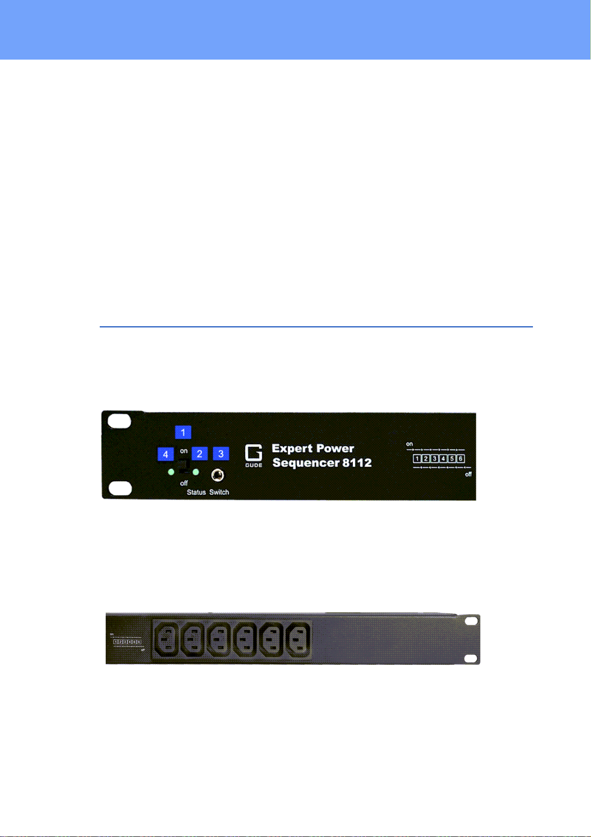
1.3 Description
The Expert Power Sequencer 8112 is a PDU that switches load outputs with delay to
avoid voltage peaks
·6 power ports can be switched in a controlled switching sequence by switches on the
unit or by external pushbuttons