GÜDE Expert PDU Energy 8340 Series User manual

Expert PDU Energy 8340 Series
Expert PDU Energy 8341 Series
Manual
© 2021 GUDE Systems GmbH
Manual Ver. 1.8.0
from Firmware Ver. 1.8

2
Expert PDU Energy 8340/8341 © 2021 GUDE Systems GmbH

3
Expert PDU Energy 8340/8341 © 2021 GUDE Systems GmbH
Table of contents
1. Device Description 5
1.1 Security Advice ....................................................................................................... 6
1.2 Content of Delivery ................................................................................................. 6
1.3 Description ............................................................................................................. 6
1.4 Installation ............................................................................................................. 7
1.5 Hotswap Drawer ..................................................................................................... 8
1.6 Technical Specifications .......................................................................................... 9
1.6.1 Electrical Measurement ........................................................................................... 9
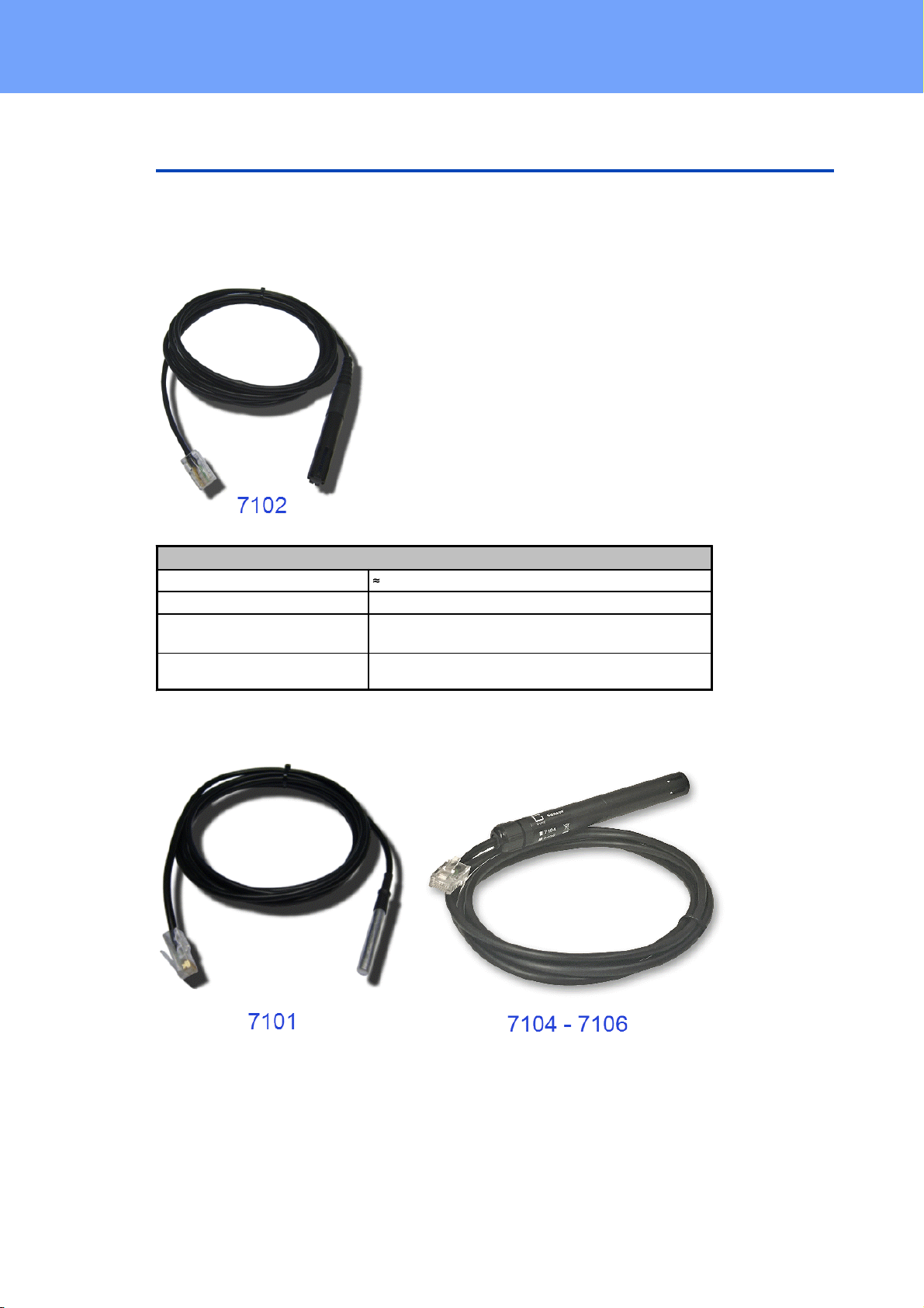
1.7 Sensor .................................................................................................................. 10
2. Operating 13
2.1 Operating the device directly ................................................................................ 14
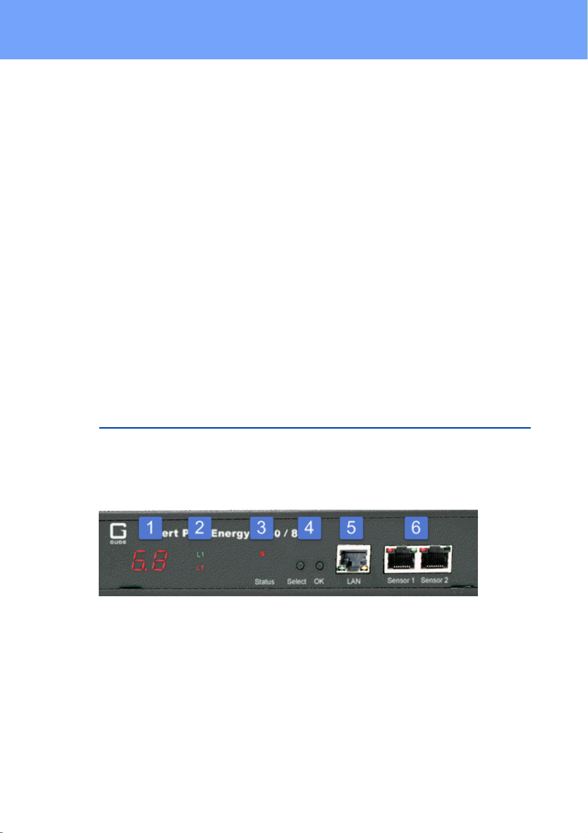
2.2 Control Panel ........................................................................................................ 14
2.3 Maintenance ........................................................................................................ 15
2.3.1 Maintenance Page ................................................................................................. 16
2.3.2 Configuration Management .................................................................................. 18
2.3.3 Bootloader Activation ............................................................................................ 19
3. Configuration 21
3.1 Ethernet ............................................................................................................... 22
3.1.1 IP Address ............................................................................................................... 22
3.1.2 IP ACL ..................................................................................................................... 24
3.1.3 HTTP ....................................................................................................................... 25
3.2 Protocols .............................................................................................................. 26
3.2.1 Console ................................................................................................................... 26
3.2.2 Syslog ..................................................................................................................... 27
3.2.3 SNMP ...................................................................................................................... 27
3.2.4 Radius ..................................................................................................................... 29
3.2.5 Modbus TCP ........................................................................................................... 30
3.2.6 MQTT ...................................................................................................................... 31
3.3 Clock ..................................................................................................................... 32
3.3.1 NTP ......................................................................................................................... 32
3.3.2 Timer ...................................................................................................................... 33
3.3.3 Timer Configuration ............................................................................................... 33
3.4 Sensors ................................................................................................................. 40
3.5 E-Mail ................................................................................................................... 41
3.6 Front Panel ........................................................................................................... 42
4. Specifications 43
4.1 Automated Access ................................................................................................ 44
4.2 Messages .............................................................................................................. 44

4
Expert PDU Energy 8340/8341 © 2021 GUDE Systems GmbH
Table of contents
4.3 IP ACL ................................................................................................................... 46
4.4 IPv6 ...................................................................................................................... 47
4.5 Radius ................................................................................................................... 47
4.6 SNMP ................................................................................................................... 48
4.6.1 Device MIB 8340 .................................................................................................... 50
4.6.2 Device MIB 8341 .................................................................................................... 52
4.7 SSL ........................................................................................................................ 53
4.8 Console ................................................................................................................. 55
4.8.1 SSH ......................................................................................................................... 59
4.8.2 Cmd 8340 / 8341 .................................................................................................... 59
4.9 Modbus TCP ......................................................................................................... 67
4.10 MQTT ................................................................................................................... 72
4.10.1 Example HiveMQ .................................................................................................... 74
5. Support 76
5.1 Data Security ........................................................................................................ 77
5.2 Contact ................................................................................................................. 77
5.3 Declaration of Conformity ..................................................................................... 78
5.4 FAQ ...................................................................................................................... 78
80
Index

Device Description

6
Expert PDU Energy 8340/8341 © 2021 GUDE Systems GmbH
Device Description
1 Device Description
1.1 Security Advice
·The device must be installed only by qualified personnel according to the following
installation and operating instructions.
·The manufacturer does not accept responsibility in case of improper use of the
device and particularly any use of equipment that may cause personal injury or ma-
terial damage.
·The device contains no user-maintenable parts. All maintenance has to be per-
formed by factory trained service personnel.
·This device contains potentially hazardous voltages and should not be opened or
disassembled.
·The device can be connected only to 230V AC (50 Hz or 60 Hz) power supply sock-
ets.
·The power cords, plugs and sockets have to be in good condition. Always connect
the device to properly grounded power sockets.
·The device is intended for indoor use only. Do NOT install them in an area where ex-
cessive moisture or heat is present.
·Because of safety and approval issues it is not allowed to modify the device without
our permission.
·The device is NOT a toy. It has to be used or stored out of range of children.
·Care about packaging material. Plastics has to be stored out of range of children.
Please recycle the packaging materials.
·In case of further questions, about installation, operation or usage of the device,
which are not clear after reading the manual, please do not hesitate to ask our sup-
port team.
·Please, never leave connected equipment unattended, that can cause damage.
·Connect only electrical devices that do not have limited on-time. I.e. in case of
failure, all connected appliances have to cope with a continuous on-time without
causing damage.
1.2 Content of Delivery
The package includes:
·Expert PDU Energy 8340 / 8341
·1 x Power Supply cable (IEC C13, max. 10 A)
·Quick Start Guide
1.3 Description
The PDU Energy 8340 / 8341 can meter energy values on 2 (resp. 4) different phases
(from IEC C20 to IEC C19, max. 16 A). The device has the following features:
·Energy Metering of 2 phases (model 8340-x) or 4 phases (model 8341-x) and meas-
urement of voltage, current, active power, reactive power, apparent power, fre-
quency, phase angle, power factor
·Energy meters for all phases, continuously and resettable

7
Expert PDU Energy 8340/8341 © 2021 GUDE Systems GmbH
Device Description
·Measurement of residual current for all phases (models 8340-2, 8341-2)
·Hot Swap Drawer - The device electronics, including power supply, can be replaced
on a drawer without the need to turn off the PDU consumers
·Connecting of two optional external sensors to determine the temperature and hu-
midity, or a input switch
·One three-digit 7-segment LED displays (for display of current, external sensor val-
ues, IP-address and device status)
·Console commands via SSH and Telnet
·SSH support with public key and passwords
·Programmable timetables for console commands
·Dual TCP/IP stack with IPv4 and IPv6 support (IPv6-ready)
·Control and monitoring of the device via Ethernet with an integrated web server with
SSL encryption (TLS 1.1, 1.2, 1.3)
·Configuration with CGI parameters and JSON messages via HTTP (REST API)
·SNMP (v1, v2c and v3, traps)
·MQTT 3.1.1 Support
·Modbus TCP support
·Radius support
·Generation of messages (e-mail, syslog and SNMP traps) depending on sensor
measurement limits
·Firmware update during operation via Ethernet possible
·Encrypted e-mails (SSL, STARTTLS)
·Access protection through IP access control
·Low own consumption
·Developed and produced in Germany
1.4 Installation
Front of the device
1. Current power consumption of Phase (7-segment LED)
2. 8 plain text displays L1 to L4 as voltage indicator (green symbol) and which phase
is shown in the display (red symbol)
3. Status LED
4. Buttons "Select" and "OK"
5. Ethernet connector (RJ45)
6. External sensor connectors (RJ45)

8
Expert PDU Energy 8340/8341 © 2021 GUDE Systems GmbH
Device Description
1. - 4. Load outputs for phases L1 to L4 (IEC C19, max. 16 A)
Rear of the device
1. - 4. Load inputs for phases L1 to L4 (IEC C20, max. 16 A)
5. Mains supply (IEC C14, max. 10 A)
Start-up the device
·Connect the power cord (IEC C14, max. 10 A) to the mains supply.
·Plug the network cable into the Ethernet socket (RJ45).
·Insert optional external sensors into the sensor connectors.
·Connect the mains supply with the load inputs (IEC C20, max. 16 A), and the con-
sumers with the load outputs (IEC C19, max. 16 A). The cable connectors are se-
cured as regards their type against unintentional loosening. They must be inserted
up to the stop, otherwise there is no secure connection. The plug must not wobble in
the socket, or there is no tight connection.
1.5 Hotswap Drawer
This PDU is "hot-swap" capable. The device has a removable drawer, on which all of
the active electronics, including the power supply, is located. In case of a fault, you can
order a replacement electronics from the manufacturer. The devices connected to the
ports are not disturbed in the exchange. Specific instructions for replacement of the
electronics drawer will be delivered with the exchange electronics. Do not open the
drawer without a compelling reason, this can lead to loss of warranty.

9
Expert PDU Energy 8340/8341 © 2021 GUDE Systems GmbH
Device Description
1.6 Technical Specifications
Interfaces
1 x Ethernet port (RJ45)
1 x Mains supply (IEC C14, max.10 A)
4 x Load inputs (IEC C20, max. 16 A)
4 x Load outputs (IEC C19, max. 16 A)
2 x RJ45 for external sensor
Network connectivity
10/100 MBit/s 10baseT Ethernet
Power Supply
internal power supply (90-265V AC / -
15% / +10%)
Environment
·Operating temperature
·Storage temperature
·Humidity
0°C - 50 °C
-20°C - 70 °C
0% - 95% (non-condensing)
Case
powder coated, galvanized steel sheet
Measurements
19" (inches), 1 Rack Unit, (Depth 195
mm)
Weight
approx. 3.3 kg
1.6.1 Electrical Measurement
Electrical Measurement Specification
Category
Range
Unit
Resolu-
tion
Inaccuracy
(typical)
Voltage
90-265
V
0.01
< 1%
Current
0 - 16
A
0.001
< 1.5%
Frequency
45-65
Hz
0.01
< 0.03%
Phase
-180 - +180
°
0.1
< 1%
Active power
0 - 4000
W
1
< 1.5%
Reactive power
0 - 4000
Var
1
< 1.5%
Apparent power
0 - 4000
VA
1
< 1.5%
Power factor
0 - 1
-
0.01
< 3%
Energy Counter
Active Energy
(total)
9.999.999,999
kWh
0.001
< 1.5%
Active Energy
(temporary)
9.999.999,999
kWh
0.001
< 1.5%

10
Expert PDU Energy 8340/8341 © 2021 GUDE Systems GmbH
Device Description
1.7 Sensor
Two external sensors can be connected to the Expert PDU Energy 8340 / 8341. The
following sensors are currently available
Humidity/Temperature Sensor 7102 (End-of-Life)
Cable length
2m
Connector
RJ45
temperature range
-20°C to +80°C, ±0,5°C (maximum) and ±0,3°C (typical)
air humidity range
(non-condensing))
0-100%, ±3% (maximum) and ±2% (typical)

11
Expert PDU Energy 8340/8341 © 2021 GUDE Systems GmbH
Device Description
Product Name
7101
7104-1
7105-1
7106-1
Calibrated
Sensor
-
7104-2
7105-2
7106-2
Cable length
2m
2m
2m
2m
Connector
RJ45
RJ45
RJ45
RJ45
temperature range
-20°C to +80°C at
±2°C (maximum)
and ±1°C (typical)
-20°C to +80°C at
±2°C (maximum)
and ±1°C (typical)
-20°C to +80°C at
±2°C (maximum)
and ±1°C (typical)
-20°C to +80°C at
±2°C (maximum)
and ±1°C (typical)
air humidity range
(non-condensing)
-
-
0-100%, ±3%
(maximum) and
±2% (typical)
0-100%, ±3%
(maximum) and
±2% (typical)
air pressure range
(full)
-
-
-
± 1 hPa (typical)
at 300 ... 1100
hPa, 0 ... +40 °C
air pressure range
(ext)
-
-
-
± 1.7 hPa (typical)
at 300 ... 1100
hPa, -20 ... 0 °C
Protection
IP68
-
-
-
Product Name
7201
7202
Cable length
-
-
Connector
RJ45
RJ45
temperature range
-20°C to +80°C at ±2°C (max-
imum) and ±1°C (typical)
-20°C to +80°C at ±2°C (max-
imum) and ±1°C (typical)
air humidity range
(non-condensing)
-
0-100%, ±3% (maximum) and
±2% (typical)
The sensors are automatically detected after connect. This is indicated by the green
LED on the sensor port that is lit permanently. The sensor values are displayed at
the "Control Panel" web page:
A click on the link in the "Name" column opens the display of the Min and Max values.
The values in a column can be reset using the "Reset" button. The "Reset" button in
the name column deletes all stored Min and Max values.

12
Expert PDU Energy 8340/8341 © 2021 GUDE Systems GmbH
Device Description

Operating

14
Expert PDU Energy 8340/8341 © 2021 GUDE Systems GmbH
Operating
2 Operating
2.1 Operating the device directly
Power Indicator
If the current is shown on the 7-segment display (see Configuration - sensor ), then
the measured current values of all phases are displayed in sequential order. When no
voltage is measured (smaller 70V) the display will show three dashes, and the green
plain text displays L1 to L4 are off. The red plain text displays L1 to L4 symbolize which
phase is currently viewable in the display.
Select Phase
By repeatedly pressing the "Select" button, the phase that appears on the display, can
be selected manually. After approx 60 seconds the running through all phases re-
sumes.
Display Information
If no phase is selected, repeatedly pressing the "ok" button will show the IP-address
and the values of the external sensors on the display.
Status-LED
The Status LED shows the different states of the device:
·red: The device is not connected to the Ethernet.
·orange: The device is connected to the Ethernet and waits for data from the DHCP
server.
·green: The device is connected to the Ethernet and the TCP/IP settings are alloc-
ated.
·periodic blinking: The device is in Bootloader mode.
2.2 Control Panel
Access the web interface: http://"IP-address" and log-in.
The web page provides an overview of the energy measurement values of all phases,
as well as the external sensors, provided that they are connected.
The column "Residual Current" is only visible on models that support this feature.
40

15
Expert PDU Energy 8340/8341 © 2021 GUDE Systems GmbH
Operating
2.3 Maintenance
The actual device generation with IPv6 and SSL allows all maintenance functions in
the web interface to be carried out on the Maintenance Page .
Maintenance in the web interface
The following functions are available from the maintenance web page:
·Firmware Update
·Change the SSL certificate
·Load and save the configuration
·Restart the device
·Factory Reset
·Jump into the Bootloader
·Delete the DNS cache
Upload Firmware, Certificate or Configuration
On the Maintenance Page , select the required file with "Browse .." in the sections
"Firmware Update", "SSL Certificate Upload" or "Config Import File Upload" and press
"Upload". The file is now transferred to the update area of the device and the contents
are checked. Only now, pressing the "Apply" button will permanently update the data,
or abort with "Cancel".
Only one upload function can be initiated with a reboot, eg. you cannot transmit
firmware and configuration at the same time.
If after a firmware update, the web page is not displayed correctly anymore, this
may be related to the interaction of Javascript with an outdated browser cache. If a
Ctrl-F5 does not help, it is recommended that you manually delete the cache in the
browser options. Alternatively, you can test start the browser in "private mode".
During a firmware update, old data formats are sometimes converted to new struc-
tures. If an older firmware is newly installed, the configuration data and the energy
meters may be lost! If the device then does not run correctly, please restore the factory
settings (e.g. from the Maintenance Page ).
Actions in Bootloader mode
If the web interface of the device is no longer accessible, the device can be put into
Bootloader mode (see chapter Bootloader activation ). The following functions can
be executed using the GBL_Conf.exe application:
·Set IPv4 address, net-mask and gateway
·Turn HTTP password on and off
·Turn IP-ACL on and off
·Factory Reset
·Jump into the bootloader (can be switched on and off)
·Restart the device
For devices with relays, entering or exiting the bootloader mode does not change
the state of the relays as long as the operating voltage is maintained.
16
16
16
19

16
Expert PDU Energy 8340/8341 © 2021 GUDE Systems GmbH
Operating
The GBL_Conf.exe program is available free of charge on our website www.gude.info
and can also be found on the enclosed CD-ROM.
Interface GBL_Conf
To check the network settings with GBL_Conf.exe, start the program and choose "All
Devices" in the "Search" menu. From the list select the appropriate device. The lower
part of the left half of the window now shows the current network settings of the device.
If the IP address is displayed with the default settings (192.168.0.2), either no DHCP
server is present on the network, or there could be no free IP address assigned to it.
·Activate the Bootloader Mode (see Chapter Bootloader Mode) and choose in menu
"Search" the item "Bootloader-Mode Devices only"
·Enter the desired settings in the edit window and save them with "Save Config".
·Deactivate the boot loader mode for the changes to take effect. Select again "All
Devices" in the "Search" menu of GBL_Conf.exe.
The new network configuration is now displayed.
Factory Reset
The device can be reset to the factory default via the web interface from the Mainten-
ance Page or from the Bootloader mode (see chapter Bootloader activation ). All
TCP/IP settings are reset in this operation.
If a unit is set to factory defaults, an uploaded certificate or updated firmware will
be preserved.
2.3.1 Maintenance Page
This section provides access to important functions such as Firmware Update or Re-
start Device. It is advisable to set an HTTP password for this reason.
16 19

17
Expert PDU Energy 8340/8341 © 2021 GUDE Systems GmbH
Operating
Firmware Update: Start a firmware update.
SSL Certificate Upload: Saves your own SSL certificate. See chapter "SSL " for the
generation of a certificate in the right format.
Config Import File Upload: Loads a new configuration from a text file. To apply the new
configuration, a "Restart Device" must be executed after the "Upload".
Config File Export: Saves the current configuration in a text file.
Saving the configuration should only be carried out in an SSL connection, since it
contains sensitive password information (even if it is encrypted or hashed).
Restart Device: Restarts the device without changing the status of the relays.
Some functions such as a firmware update or changing of the IP-address and
HTTP settings require a restart of the device. A jump to the boot loader or a restart of
the device lead by no means to a change of the relay states.
Restore Fab Settings and Restart Device: Performs a restart and resets the device to
factory default .
Enter Bootloader Mode: Jumps into bootloader mode, where additional settings can be
made with GBL_Conf.exe.
Flush DNS Cache: All entries in the DNS cache are discarded and address resolutions
are requested again.
54
20

18
Expert PDU Energy 8340/8341 © 2021 GUDE Systems GmbH
Operating
Config/Status View: status.html: Displays the status.html page with the JSON data.
Config/Status Download: export.json: Direct file download of JSON data from
status.hml.
2.3.2 Configuration Management
The device configuration can be saved and restored in the maintenance area .
The "Config File Export" function can be used to save the current configuration as a
text file. The syntax used in the configuration file corresponds to the commands of the
Telnet console. If the configuration of a device is to be restored from a text file, load
the file with "Upload" and restart the device with "Restart Device".
Saving the configuration should only be carried out in an SSL connection, since it
contains sensitive password information (even if it is encrypted or hashed). For the
same reasons, it is advisable to carefully handle the generated configuration files when
archiving.
Editing the configuration file
It is possible to customize a saved configuration file with a text editor for your own
needs. For example, one scenario would be to use a script language to automate the
creation of many customized versions of a configuration, then equip a large number of
devices with an individualized configuration. Also Upload and restart with CGI com-
mands can be done in scripting languages. With use of the comment sign "#" you can
quickly hide single commands or add personal notes.
If you modify a configuration file manually, it is not always clear which limits are allowed
for parameters. After uploading and restarting, commands with invalid parameters are
ignored. Therefore, the generated configuration includes comments describing the
boundaries of the parameters. Where "range:" refers to a numeric value, and "len:" to a
text parameter. E.g:
email auth set 0 #range: 0..2
email user set "" #len: 0..100
The command "system fabsettings" from the beginning of a generated configuration
file brings the device into the factory state, and then executes the individual commands
that modify the configuration state. It may be desirable to make the changes relative to
the current configuration, and not out of the factory state. Then the "system fabset-
tings" should be removed.
No output of default values
The configuration file contains (with exceptions) only values which differ from the de-
fault. The command "system fabsettings" (go to the factory state) from the beginning of
a generated configuration file should not be removed, otherwise the device can get in-
16

19
Expert PDU Energy 8340/8341 © 2021 GUDE Systems GmbH
Operating
completely configured.
Configuration via Telnet
The configuration files can in principle also be transferred in a Telnet session, but then
the settings are changed during operation, and not completely when restarting, as it
would have been the case with an upload. It can happen that events are triggered at
the same time as the device is configured. One should therefore:
a) disable the function
b) completely parametrize
c) reactivate the function
An example:
email enabled set 0
email sender set "" #len: 0..100
email recipient set "" #len: 0..100
email server set "" #len: 0..100
email port set 25
email security set 0 #range: 0..2
email auth set 0 #range: 0..2
email user set "" #len: 0..100
email passwd hash set "" #len: 0..100
email enabled set 1 #range: 0..1
2.3.3 Bootloader Activation
The configuration of the device from the application "GBL_Conf.exe" is only possible, if
the device is in Bootloader Mode.
Activation of the Bootloader Mode
1) via push button:
·Hold both buttons for 3 seconds
2) or
·Remove the power supply
·Hold down the "Select" button. If the push button is recessed, use a pin or paper clip
·Connect the operating voltage
3) by Software: (only if "Enable FW to BL" was previously activated in the
"GBL_Conf.exe" application)
·Start the "GBL_Conf.exe" program
·Do a network search with the "Search" menu action
·Activate in menu "Program Device" the item "Enter Bootloader"
4) via web interface:
Press "Enter Bootloader Mode" on the maintenance web page.
Whether the device is in Bootloader mode, is indicated by the flashing of the status
LED, or it is shown in "GBL_Conf.exe" application after a renewed device search (ap-
16

20
Expert PDU Energy 8340/8341 © 2021 GUDE Systems GmbH
Operating
pendix "BOOT-LDR" after the device name). In Bootloader mode the program
"GBL_Conf.exe" can disable the password and the IP ACL, perform a firmware update,
and restore the factory settings.
For devices with relays, entering or exiting the bootloader mode does not change
the state of the relays as long as the operating voltage is maintained.
Abandonment of the Bootloader Mode
1) via push button:
·Hold both buttons for 3 seconds (only if the device has 2 buttons)
2) or
·Remove and connect the power supply without operating a button
3) by Software:
·Start the "GBL_Conf.exe" application
·Do a network search with the "Search" menu action
·In menu "Program Device"activate the item "Enter Firmware"
For devices with relays, entering or exiting the bootloader mode does not change
the state of the relays as long as the operating voltage is maintained.
Factory Reset
If the device is in bootloader mode, it can always be put back to its factory default. All
TCP/IP settings are reset in this operation.
If a unit is set to factory defaults, an uploaded certificate or updated firmware will
be preserved.
1) via push button:
·Activate the Bootloader Mode of the device
·Hold down the button (or the "Select" button for devices with 2 buttons) for 6
seconds. If the push button is recessed, use a pin or paper clip
·The status LED will blink in a fast rhythm, please wait until the LED blinks slowly
(about 5 seconds)
2) by Software:
·Activate the Bootloader Mode of the device
·"Start the GBL_Conf.exe" program
·In menu "Program Device"activate the item "Reset to Fab Settings"
·The status LED will blink in a fast rhythm, please wait until the LED blinks slowly
(about 5 seconds)
This manual suits for next models
1
Table of contents
Other GÜDE Switch manuals
Popular Switch manuals by other brands

Toshiba
Toshiba MBSWH-150-F3-KK installation guide

SMC Networks
SMC Networks TigerSwitch SMC6128L2 Management guide

Planex
Planex SWP-0008F user manual

PABX
PABX TC-208 SP instruction manual

Eggtimer Rocketry
Eggtimer Rocketry Rev A4a Assembly and user's manual

Moxa Technologies
Moxa Technologies EtherDevice EDS-P510 Series Hardware installation guide

Automationdirect.com
Automationdirect.com Stride SE3 Series manual

LEGRAND
LEGRAND 7 521 90 quick start guide

Kramer
Kramer VS-211HDx1 user manual

D-Link
D-Link DES-1016A/C1A Quick installation guide

Vantec
Vantec UGT-AH710U3-BK installation guide

Austin Hughes Electronics
Austin Hughes Electronics CyberView M-802 Specifications