G-Force CRW 300 Series User manual

ESSENTIAL FEATURES
The retractable-type fall arrester device including rescue lifting
and lowering device is a component of the personal protective
equipment against falls from a height.
The device performs two functions relating to prevention
against falls from a height - fall arresting function (as a
retractable fall arrester) and rescue function. The equipment
conforms to the following standards: EN360, EN1496 class B.
?max. working load - 140kg;
?min. working load - 50 kg;
?working length - 25 m;
?automatic brake which prevent self-contained descent of a
person;
?hand operated winch;
The device is designed
for protection one person only.
TECHNICAL DATA
type of the equipment
reference number of the device
including the working length of
the device
MARKING OF THE DEVICE
before use read
the manual
admissible weight
of the user
store the device in
a protected place
Inspect the device
before each use
range of operating
temperatures
check locking before
each use
maximal admissible
cable deflection from
the vertical line
use only a full body
harness conform
to EN 361
don't realese
unwinded cable
rapidly
don't repair the
device yourself
don't use the device
with damaged cable
XXX kg
RETRACTABLE TYPE
FALL ARRESTER
Reference No.:
Cable length:
Serial number:
Date of manufacture:
CRW 300 25
25 m
0000000
12.2005
Cable retractor with energy dissipating brake.
Informative and identity labels
Casing made of aluminium alloy.
Connecting handle -for transporting and
anchoring to structure
Working cable made of 4.8mm galvanized wire
rope.
Snap hook with swivel function
(Range of alternative hooks.
with fall indicator as an option)
Lifting and lowering hand operated winch with
automatic brake.
CRW 300 xx
(xx - working length in meters)
Reference
number:
Instruction Manual
RETRACTABLE TYPE FALL ARRESTER
RESCUE LIFTING DEVICE
Read carefully
the manual
before use
the equipment
EN 360:2002
EN 1496:2006 class B
cable/webbing length
serial number of the device
month and year of manufacture
device manufacturer or distributor
European Standards
CE mark and number of notified body
inspecting the equipment
Month and year of the manufacturer's next inspection.
Don't use the device after this date.
Attention: Before the first use mark the date of the first
inspection (date of first use +12 months, (e.g. first use
01.2006 - mark inspection 01.2007)
TIME OF USAGE
TCRW300 device ohere is no limit of use of the n condition
punctual carried out annual inspections.

It's possible to instal the CRW 300 directly on arrester handle to a structure with the aid of a
the structural anchor element . connector or sling complying with EN362 or
EN795 standards .
An anchor point for the
should , and the
work carried out in such a way, as to
minimise both the potential for falls and
potential fall distance. The shape and
construction of the anchorpoint shall not
allow to self-acting disconnection of the
equipment. The m
It is
recommended to use certified and marked
structural anchor point
the N795 standard.E
Connecting the fall arrester to a structural
anchor point should be done by joining the
(point) The
retractable fall arrester shall be installed (fig.2-1)
above the user. When the device is installed in the vertical
device have stable structure line above the user the minimal clearence
distance below working level shall be 1,5 m.
When the cable of the retractable fall
arrester is deflected from vertical line a
pendulum effect occurs during fall arresting.
In order to minimise the pendulum effect the
inimal strength of the cable deviation angle from vertical shall
structural anchor point should be 12 kN. never exceed 40°. For this purpose the
user is permitted to move laterally through
or device, conform to distance “l” not greater than 1/2 “v” . The
clearance distance bellow working level
must be greater than 1,5 m+ lateral distance
“l” (fig. 2-2).
The CRW 300 device may be used together The CRW300 should be mounted into adapter
with the TM9 / TM11 tripods. frame by inserting the cable sleeve into
Installation on the tripod may be done with the adapter opening (step”1”) and than slide onto
aid of special fixing adapters, respectively: AT the adapter fork (step”2”). Secure the CRW
171 (for TM9) and AT172 (for TM11) and the device with the aid of the adapter pin (step“3”).
pulley RUP 942 (fig.2-4). After that, unwind the CRW300 cable form the
device and belay on the pulley RUP042
The way of The CRW300 inastallation on the
(step”4”).
tripod is described on the fig.2-5.
UTILIZATION WITH A TRIPOD
fig. 2-3
fig. 2-2
v
retractable type
fall arrester
anchor point
l
z
working
level
pendulum
effect
ground
level
o
max 40
INSTALLING THE CRW 300 ON A STRUCTURAL ANCHOR ELEMENT
UTILIZATION WITH A BODY HARNESS
A full body harness conform to the EN 361 is standard. Always protect the gate of the
the only accepted device for keeping a body snap hook against accidental opening with
in the fall arrest system which utilize the locking gear.
CRW300 device. During employment the
EN360 funcion of the device, the device
lanyard shoul be connected only to full body
harness fastening points (buckles, loops)
marked with the capital letter “A” (fig.2-3).
During employment the EN1496 function of
the device, apart from the EN361 “A” marked
attachment point, the EN1497 attachment
point may be used.
A connection between CRW300 device and
the harness attachment point shoud be done
with the aid of connector conform to EN 362
fig. 2-1
fig. 2-4
AT 171 for TM9
AT 172 for TM11
TM9 or TM11
RUP 042
fig. 2-5
“1”
“3” “4”
“2”

?personal protective equipment shall only be used by a person trained and
competent in its safe use.
?personal protective equipment must not be used by a person with medical
condition that could affect the safety of the equipment user in normal and
emergency use.
?a rescue plan shall be in place to deal with any emergencies that could arise !personal protective equipment must be withdrawn from use immediately
during the work. when any doubt arise about its condition for safe use and not used again
?it is forbidden to make any alterations or additions to the equipment without until confirmed in writing by equipment manufacturer or his representative
the manufacturer's prior written consent. after carried out the detailed inspection.
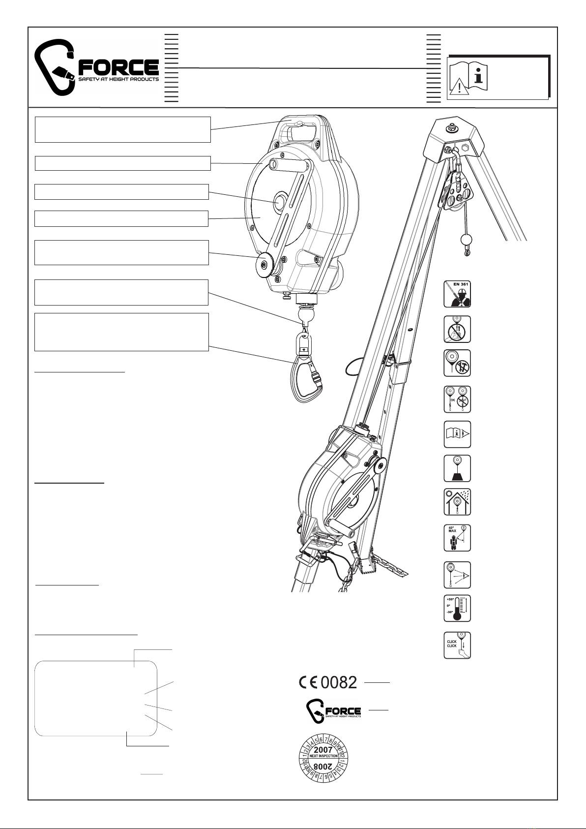
?any repair shall only be carried out by equipment manufacturer or his ?An anchor device or anchor point for the fall arrest system should
certified representative. , and the work carried out in such a way, as to minimise both
?personal protective equipment shall not be used outside its limitations, or for the potential for falls and potential fall distance. The anchor device/point
any purpose other than that for which it is intended. should be placed above the user . The shape and construction of the
?personal protective equipment should be a personal issue item. anchor device/point shall not allowed to self-acting disconnection of the
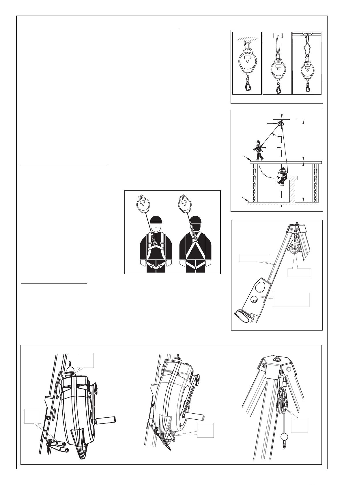
?before use ensure about the compatibility of items of equipment assembled equipment. t is recommended to use certified and marked structural anchorI
into a fall arrest system. Periodically check connecting and adjusting of the point with Ethe N795 standard. The m
equipment components to avoid accidental loosening or disconnecting of the
components. ?it is obligatory verify the free space required beneath the user at theto
?it is forbidden to use combinations of items of equipment in which the safe workplace before each occasion of use the fall arrest system, so that, in the
function of any one item is affected by or interferes with the safe function of case of a fall, there will be no collision with the ground or other obstacle in
another. the fall path. The required value of the free space should be taken from
?before each use of personal protective equipment it is obligatory to carry out instruction manual of used equipment.
a pre-use check of the equipment, to ensure that it is in a serviceable ?there are many hazards that may affect the performance of the equipment
condition and operates correctly before it is used. and corresponding safety precautions that have to be observed during
?during pre-use check it is necessary to inspect all elements of the equipment equipment utilization, especially:- trailing or looping of lanyard overdevice
in respect of any damages, excessive wear, corrosion, abrasion, cutting or sharp edges,- pendulum falls,- extreme temperature,- chemical reagents,-
incorrect acting, especially retractable fall arresters - cable or webbingin electrical conductivity; - .
retracting and locking function; ?
?
?it is essential for the safety of the user that if the product is re-sold outside
the original country of destination the reseller shall provide instructions for
use, for maintenance, for periodic examination and for repair in language of
the country in which the product is to be used.
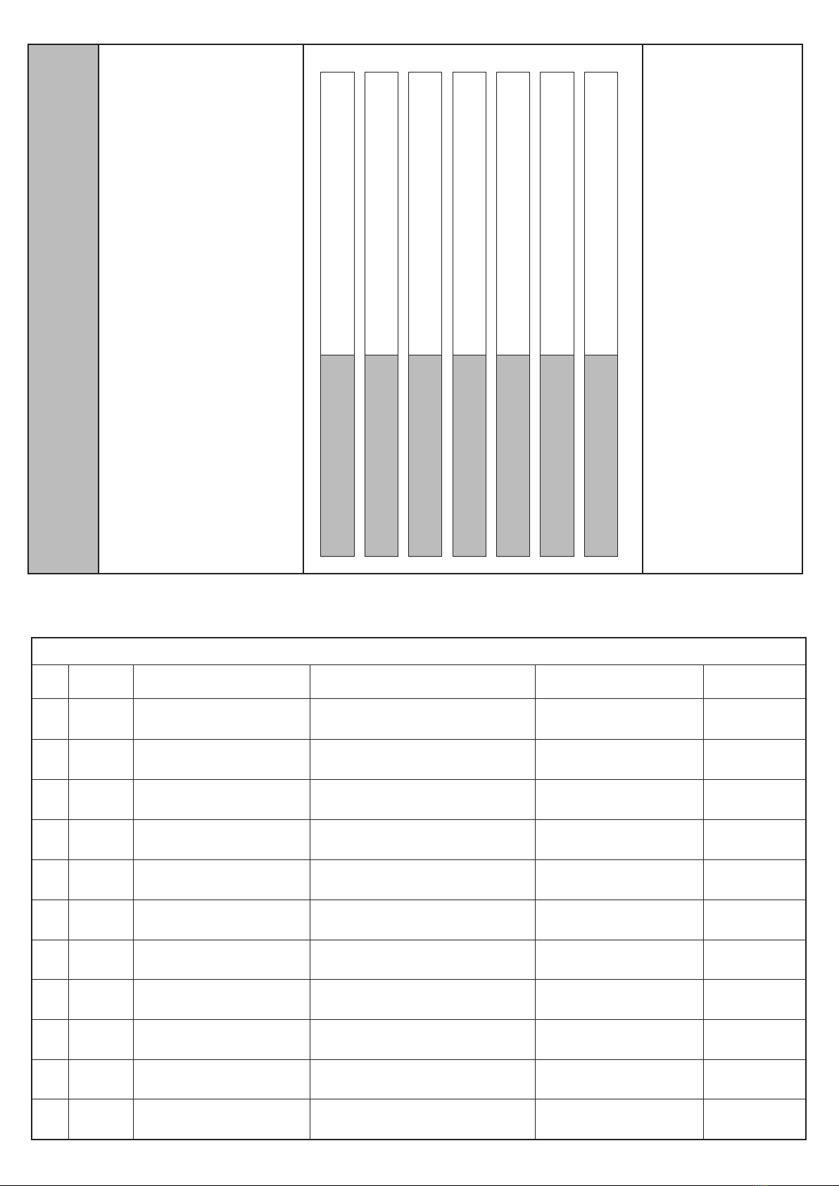
!
device name, serial number, date of purchase and date of first operation,
user name, information concerning repairs and inspections and withdrawal
from use. The Sheet should be completed by the person responsible for
safety equipment in a given place of work. Equipment without a properly
completed Operation Sheet cannot be used.
have
stable structure
inimal strength of any other structural
anchor point should be 12 kN.
dust laden and gre sy environmenta
Regular periodical inspections are essential in terms of equipment condition
and safety of users. Only fully operational equipment is able to provide
safety.The retractable fall arrester must be withdrawn from use and undergo
a complete periodical inspection and maintenance, at least once a year
(after 12 months of use). The inspection must be carried out by the
equipment manufacturer or an authorised representative of the
manufacturer. Such an inspection should check all equipment elements and
functions according valid producer Service Manual. The date of the
subsequent inspection shall be specified after the periodical inspection has
been completed.
The factory where equipment is stored/ used is responsible for keeping the
Operation Sheet for a particular device. The Seet should include at least: the
personal protective equipment must be transported in the package (e.g.: bag
made of moisture-proof textile or foil bag or cases made of steel or plastic)
to protect it against damage or moisture.
?the equipment can be cleaned without causing adverse effect on its
materials. For textile products use mild detergents for delicate fabrics, wash
by hand or in a machine and rinse in water. Plastic parts can be cleaned
only with water. When the equipment becomes wet, either from being in use
or when due cleaning, it shall be allowed to dry naturally, and shall be kept
away from direct heat. In metallic products some mechanic parts (spring,
pin, hinge, etc.) can be regularly slightly lubricated to ensure better
operation. Other maintenance and cleaning procedures should be adhered
to detailed instructions stated in the anual of the equipment.Service M
?personal protective equipment should be stored loosely packed, in a well-
ventilated place, protected from direct light, ultraviolet degradation, damp
environment, sharp edges, extreme temperatures and corrosive or
aggressive substances.
FUNDAMENTALS RULES OF USING OF A PERSONAL PROTECTIVE EQUIPMENT
STORAGE
T CRW300 device shouldhe be stored in a dry, ventilated, room
temperature and free of places. Before theaggresive chemicals first
usage the device must be stored in manufacturer package.
CLEANING
E CRW300 casing and the wire rope lanyardxternal surface of the can
be cleaned with a cloth. Do not use any acid or basic solvents.wet
Cable devices leave to dry in the state. The cableunwound lanyard
can be slightly lubricated with machine oil.
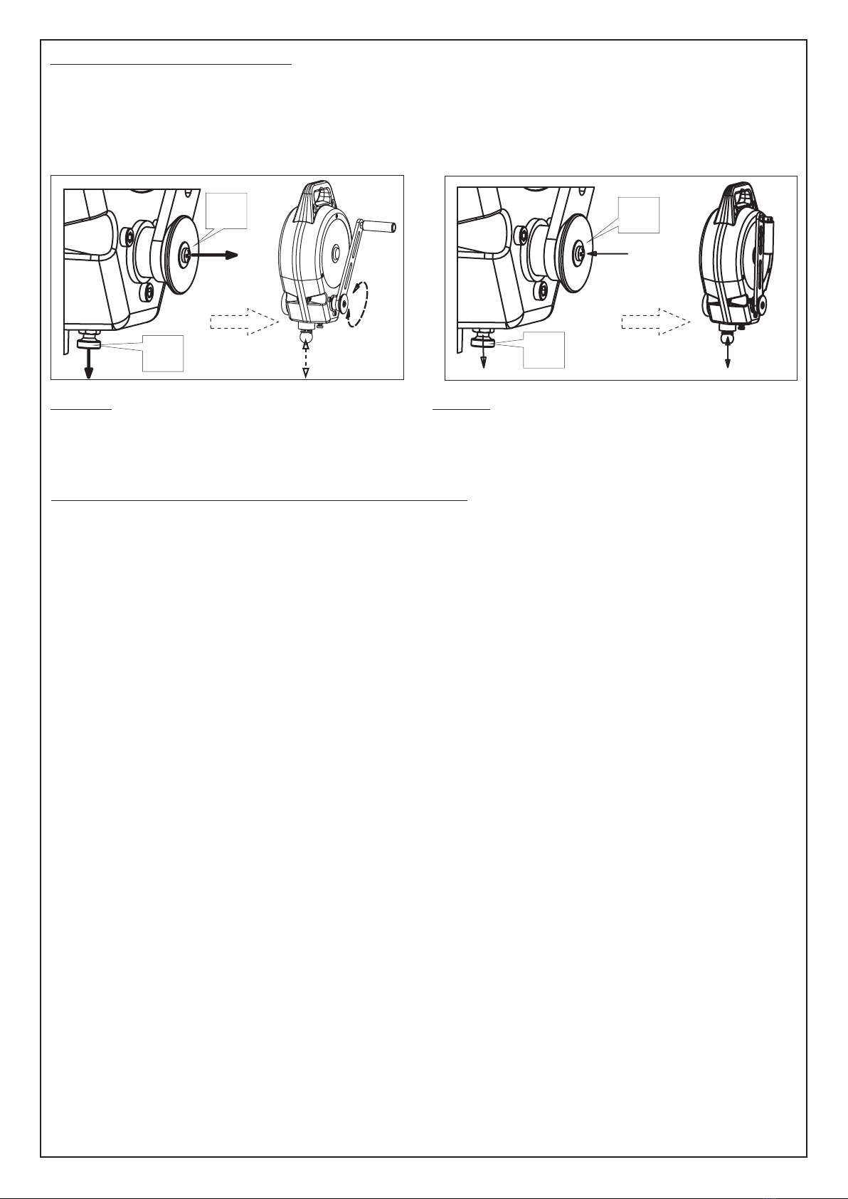
SWITCHING BETWEEN EN360 AND EN1496
Only one of the EN360 or EN1496 functions and next pull out the crank axle “b” (fig.3-1). there is neccesity to rescue of the user. In
of the device may be applied at he same Than, in the consequence of cranking, the order to change the EN1496 function to
time.To change the function, the operation device cable is moved up or down, under EN360 pull out the locking pin “a” and next
described on the fig.3-1 and 3-2 should be control. The switching from EN360 to push in the crank axle “b” inwards (fig. 3-2).
done. In particular, to change from EN360 to EN1496 function may be done especially Than the device will act as a retractable fall
EN1496 function, pull out the locking pin “a” when the CR300 have arrested a fall and arrester.
fig. 3-1
“a”
“b”
fig. 3-2
“a”
“b”

IDENTITY CA RD
of a personal protective equipment
It is the responsibility of the user organisation to provide the identity card and to fill
in the details required.
The identity card should be filled in only by a competent person responsible for
protective equipment.
The identity card should be filled in before the first use of the equipment.
Any information about the equipment like: periodic inspections, repairs, reasons
of equipment's withdrawn from use shall be noted.
The identity card should be storaged during a whole period of equipment
utilization. Do not use the equipment without the identity card.
DATE OF PURCHASE
MODEL AND TYPE OF EQUIPMENT
SERIAL NUMBER
DATE OF MANUFACTURE
REF. NUMBER
DATE OF FIRST USE
USER NAME
PERIODIC EXAMINATION AND REPAIR HISTORY
1
2
DATE REASON FOR
SERVICING / REPAIR
3
4
5
6
7
8
9
10
11
CONDITION OF DEVICE
AFTER SERVICING
NAME AND SIGNATURE
OF COMPETENT PERSON
DATE OF NEXT
EXAMINATION
SafetyLiftinGear.com
Unit R1D Rockingham Gate Poplar Way West Cabot Park Bristol BS11 0YW
Tel: 0808 123 69 69 Fax: 0117 9381 602 [email protected]
Other G-Force Safety Equipment manuals
Popular Safety Equipment manuals by other brands

ABS Safety
ABS Safety Lock Loop installation manual

Elkron
Elkron HPA701 installation manual

Tractel
Tractel FABA-Klassik A11 Operating and maintenance instructions

SKYLOTEC
SKYLOTEC SIRIUS Instructions for use

Tractel
Tractel skysafe MP 03 Assembly and operating manual

FrontLine
FrontLine COM345K Operation and instruction manual