E2S GNExCP6A-BG User manual

European Safety Systems Ltd. Impress House, Mansell Road, Acton, London W3 7QH www.e2s.com Tel: +44 (0)208 743 8880
Document D154-00-001-IS Issue 6 12-09-2022 Sheet 1 of 2
INSTRUCTION MANUAL
GNExCP6A-BG Break glass Manual Call Point
For use i
n Flammable Gas and Dust Atmospheres
GNExCP6A-BG
Manual Call Point – Break Glass
For use in Flammable Gas and
Combustible Dust Atmospheres.
1) Introduction
The GNExCP6A-BG is a break glass manual call
point which is certified to the European and
International Gas and Dust standards. The unit
meets the requirements of the ATEX directive
2014/34/EU, IECEx and UKEX schemes.
The call point can be used in hazardous areas
where potentially flammable gas and dust
atmospheres may be present.
All units have no monitoring resistors, diodes or
zener diodes and are not fitted with an LED
indicator.
The units are Group II, EPL (equipment protection
level) Gb. The equipment is certified ‘Ex db eb IIC
T6 Gb’ and as such may be used in Zones 1 and 2
with flammable gases and vapours with apparatus
groups IIA, IIB & IIC and temperature classes T1,
T2, T3, T4, T5 and T6.
These units are also Group III, EPL Db. The
equipment is certified ‘Ex tb IIIC T75ºC Db’ and as
such may be used in Zones 21 and 22 for
combustible dusts groups IIIA, IIIB & IIIC.
2) Ratings & Markings
All units have a rating label, which carries the
following important information:-
Unit Type No.:
GNExCP6A-BG Manual Call Point
Input Voltage:
AC voltage 250V Max Current 5.0A Max
DC voltage 250V Max Current 0.25A Max Resistive
load : 0.03A Max Inductive load
DC voltage 125V Max Current 0.5A Max Resistive
load : 0.03A Max Inductive load
DC voltage 75V Max Current 0.75A Max
DC voltage 50V Max Current 1.0A Max
DC voltage 30V Max Current 5.0A Max Resistive
Load; Inductive Load 3.0A Max
DC voltage 12V Max Current 5.0A Max
Code:
Ex db eb IIC T6 Gb
Ex tb IIIC T75 ºC Db
IP66
–40ºC <= Ta <= +70ºC
Certificate No.:
SIRA 09ATEX3286X
IECEx SIR 09.0121X
CSAE 21UKEX3556X
Epsilon x: II 2GD
CE Marking
Notified 2813
Body No.
UKCA Marking
Notified Body No. 0518
Year/Serial No. i.e. 20/1CP6ABG000001
WARNING - DO NOT OPEN WHEN AN
EXPLOSIVE ATMOSPHERE MAY BE PRESENT
ELECTROSTATIC HAZARD – CLEAN ONLY
WITH A DAMP CLOTH
3) Type Approval Standards
The call point has an EC Type examination
certificate issued by SIRA and have been approved
to the following standards:-
EN60079-0:2018 / IEC60079-0:2017
EN60079-1:2014 / IEC60079-1:2014
EN60079-7:2015 / IEC60079-7:2017
EN60079-18:2015 / IEC60079-18:2014
EN60079-31:2014 / IEC60079-31:2013
The equipment is certified for use in ambient
temperatures in the range -40oC to +70oC and shall
not be used outside this range.
4) Installation Requirements
Installation of this equipment shall only be carried
out by suitably trained personnel in accordance
with the applicable code of practice e.g.
IEC 60079-14/EN 60079-14
Repair of this equipment shall only be carried out
by the manufacturer or in accordance with the
applicable code of practice e.g. IEC 60079-19/EN
60079-19.
Refer to certificates SIRA 09ATEX3286X, IECEx
SIR 09.0121X and CSAE 21UKEX3556X for
special conditions of safe use.
The certification of this equipment relies on the
following materials used in its construction:
Enclosure: GRP - Glass Reinforced Polyester
Through enclosure mechanism: Plastic Nylon Zytel
Injection Moulded
Sealing of enclosure and mechanism: O-ring
Acrylonitrile-Butadiene Rubber
If the equipment is likely to come into contact with
aggressive substances, then it is the responsibility
of the user to take suitable precautions that prevent
it from being adversely affected, thus ensuring that
the type of protection is not compromised.
“Aggressive substances” - e.g. acidic liquids, gases
or solvents that may affect polymeric materials.
“Suitable precautions” - e.g. regular checks as part
of routine inspections or establishing from the
material’s data sheet that it is resistant to specific
chemicals.
Under extreme conditions the unit may generate an
ignition-capable level of electrostatic charges. The
unit must not be installed in a location where it may
be subjected to external conditions (such as high
pressure steam) which may cause a build-up of
electrostatic charges on non-conducting surfaces.
Cleaning of the unit must only be carried out with a
damp cloth.
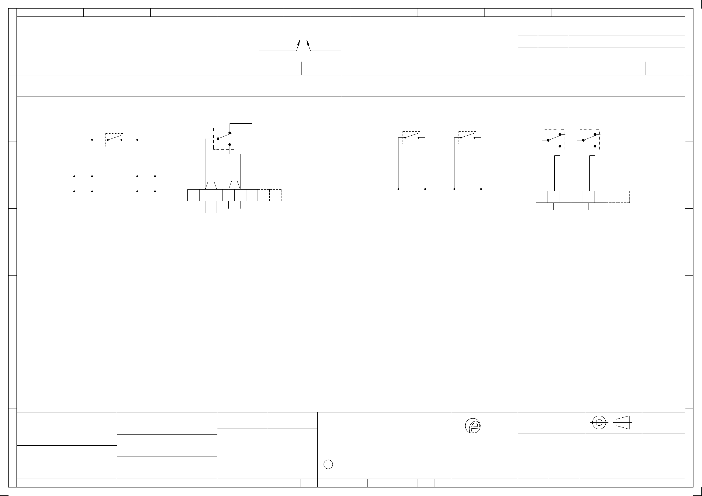
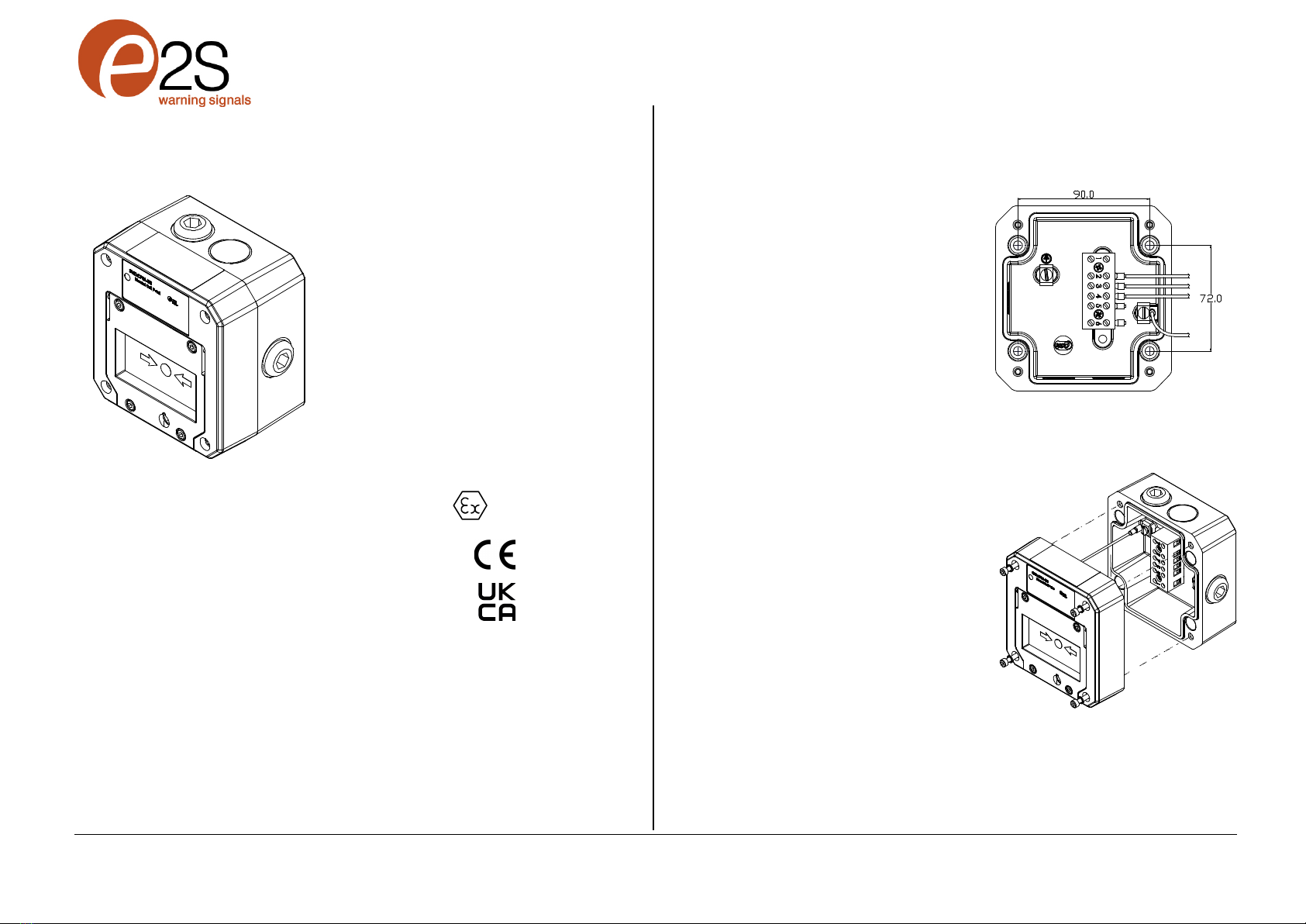
5) Call Point Location and Mounting
The location of the call point should enable ease of
access for operation and testing. The unit should
be mounted using the 4 off fixing holes which will
accept up to M4 sized fixings.
View of base unit showing fixing centres (in mm).
To gain access to the mounting holes in the base
the front cover must be removed.
This is achieved by removing the 4 off M4 cap
head bolts holding on the cover.
Once the screws are removed the cover will hang
down out of the way to gain access to the Ex e
terminal block, the internal earth terminal and
mounting hole recesses.

European Safety Systems Ltd. Impress House, Mansell Road, Acton, London W3 7QH www.e2s.com Tel: +44 (0)208 743 8880
Document D154-00-001-IS Issue 6 12-09-2022 Sheet 2 of 2
6) Earthing
The unit has an internal earth terminal.
It is recommended that a cable crimp lug is used
on the earth wires.
The internal earth wire is placed under a earth
clamp which will stop the cable twisting. This is
secured by an M4 screw and spring washer.
Internal Earth Ex e terminal block
terminal
Note: Depending on options chosen an 8-Way DIN
Rail or 6-Way terminal block may be selected.
7) Cable connections
There are 3 off cable entries for M20x1.5 Ex e
approved cable glands or stopping plugs with a
minimum ingress protection of IP66.
The unit can be wired in a number of different ways
depending whether normally open or normally
closed contacts are required. See wiring schematic
D154-06-001 for wiring options.
When wiring to Increased Safety terminal
enclosures, you are only permitted to connect one
wire into each way on the terminal block, unless a
pair of wires are crimped into a suitable ferrule. For
the six-way terminal block wire sizes allowable are
0.5mm² to 4.0mm². For the 8-way DIN rail wire
sizes allowable are 0.5mm² to 2.5mm²
Leads connected to the terminals shall be insulated
for the appropriate voltage and this insulation shall
extend to within 1mm of the metal of the terminal
throat. They shall only be installed and wired with
cable in an ambient temperature of -10°C to +80°C
All terminal screws, used or unused, shall be
tightened down to between 0.5 Nm and 0.7 Nm.
8) Testing unit operation
The break glass unit can be tested without the
need to break/replace the frangible glass element.
A test key is used to mechanically drop the glass
down activating the switch.
The test key is inserted in the test cam and rotated
clockwise by an angle of 60º the glass element will
visibly drop down in the viewable window.
The call point switch will now change over its
contacts to operate the alarm.
Once testing is complete the unit needs to be
reset, the test key is rotated back anticlockwise by
an angle of 60º back to its original position. The
glass element should now raise up so it is level
again in the viewable window.
1. 2. 3.
Insert test Hold in Rotate back
Key rotate position anticlockwise
clockwise during to reset
60º test
9) Replacement of glass element
If the break glass unit has been operated the
broken glass element can be quickly replaced.
The break glass cover plate is removed by
unscrewing the 4 off M4 cap head screws attaching
it.
Once the cover is removed the broken glass will be
free to be removed, clean out any other fragments
of glass carefully.
To fit the new glass element rotate the top cam
clockwise by an angle of 50º (use a 6mm Allen
key) this will than allow the glass to fit back into the
pocket it sits in, resting on the pivot point and test
cam, release the top cam to rest on the top of the
glass element.
Pivot point Test Cam Top Cam (rotate)
Replace the cover plate and tighten the 4 off M4
cap head screws.
Ensure the glass element is free to move under the
cover plate. This can be done by running through
the units test operation. See section 8 of this
instruction manual.
10) SIL 2 Reliability Data
Reliability and Functional safety IEC/EN61508
which has been assessed and is considered
suitable for use in low demand safety function:
• Random Hardware Failures and Systematic
Failures (route 2H)
• As an unvoted item (i.e. hardware fault tolerance
of 0) at SIL 2
The product was assessed against failure modes:
• Failure to close a contact when the call point is
struck with specified force
• Failure to open a contact when the call point is
struck with specified force
• Spurious output despite no input
Integrity in respect of failure to close SIL 2
Total Failure rate 0.133 pmh
“hazardous” failure rate (revealed) 0 pmh
“hazardous” failure rate (unrevealed) 0.1 pmh
“safe” failure rate (revealed) 0.033 pmh
“safe” failure rate (unrevealed) 0
Diagnostic Coverage 99%
System type A
Hardware Fault Tolerance 0
Safe Failure Fraction >99%
PFD (hazardous failure) 1.25 x 10⁻³
Proof Test Interval Up to 1 year

+
RYB
M/S 2M/S 1
M/S 2
+
-
M/S 1
-
654321
RYB
7 8
5
-
4
-
3
+
2
+
1
+
2
-
4
+
5
-
7 8
--
++
M/S 1
M/S 1
654321
R Y B
R.N.POTTS
warning signals
2S
GNExCP6A CALL POINTS
ADDED T7 & 8 FOR DIN OPTION
1
2D.A.H - 26-08-2020
INTRODUCTION
WWW.E2S.COM
C
LONDON W3 7QH
ACTON
MANSELL ROAD
IMPRESS HOUSE
EUROPEAN SAFETY SYSTEMS LTD
07-02-20
07-02-20
1
AS PER LATEST DATE OF ISSUE SHOWN ABOVE
EUROPEAN SAFETY SYSTEMS LTD.
WRITTEN CONSENT.
MANUFACTURING OR TENDERING PURPOSES WITHOUT THEIR
ANGULAR DIMENSIONAL TOLS
STANDARDS
MOD No. REASON - INITIAL - DATEISSUE
DATE
APPROVED
CHECKED DATE
DATE
DRAWN WEIGHT (Kg)
SURFACE FINISH
MATERIAL
ALTERNATIVE MATERIAL SHEETSCALE
TITLE
A3
LINEAR DIMENSIONAL TOLS
DO NOT SCALE
ALL DIMENSIONS IN MM
DRAWING NUMBER
A
B
C
D
E
F
G
109
G
F
E
78
6
5
D
C
134
2
A
B
D154-06-001
D.A.H - 22-02-2022
D.HOWGILL
R.N.POTTS
07-02-20
OF
IF IN DOUBT, ASK -
POINT WIRING SCHEMATIC
GNExCP6A-BG/PB/PT MANUAL CALL
D.A.H - 07-02-2020
NTS 1
THIS DRAWING AND ANY INFORMATION OR DESCRIPTIVE
MATTER THEREIN IS COMMUNICATED IN CONFIDENCE AND
IS THE COPYRIGHT PROPERTY OF EUROPEAN SAFETY
SYSTEMS LTD. NEITHER THE WHOLE OR ANY EXTRACT MAY
BE DISCLOSED, LOANED, COPIED OR USED FOR
DRAWING TO BS8888:2000
GEOMETRIC TOLERANCES TO ISO1101:1983
FORMAT UPDATED
3
Terminals [t]
SWITCH TYPE [s] Single Switch
Switch Type [s]
GNEXCP6A-BG[s][t][l][e][m][d][v][o][x][u]
CONFIG. 2
SWITCH TYPE [s]
DUAL SWITCH
WIRING SCHEMATIC FOR PRODUCTS:
CONFIG. 1SINGLE SWITCH
[S] Dual Switch[D]
GNExCP6A-BG
GNExCP6A-PB
GNExCP6A-PT
Operated Condition
(Glass Broken / Button pushed in)
Terminal +(1) & (3)
Terminal +(4) & (6)
switch contacts open
Terminals +(1) & -(2)
Terminals +(4) & -(5)
switch contacts closed
Circuit shown in Unoperated condition
Unoperated condition
(Glass Intact / Standby Condition)
Terminal +(1) & (3)
Terminal +(4) & (6)
switch contacts closed
Terminals+ (1) &- (2)
Terminals +(4) & -(5)
switch contacts open
Operated Condition
(Glass Broken / Button pushed in)
Terminal +(2,3) & (6)
switch contacts open
Terminals +(2,3) & -(4,5)
switch contacts closed
Circuit shown in Unoperated condition
Unoperated condition
(Glass Intact / Standby Condition)
Terminal +(2,3) & (6)
switch contacts closed
Terminals +(2,3) & -(4,5) switch contacts open

E2S Telephone: +44 (0)20 8743 8880 Fax: +44 (0)20 8740 4200 Email: s[email protected]m www.e2s.com DC-043_Issue_J (GNExPC6) - Page 1 of 2 - QAF_252_Issue_5
EU Declaration of Conformity
Manufacturer: European Safety Systems Ltd.
Impress House, Mansell Road, Acton
London, W3 7QH
United Kingdom
Authorised Representative: E2S Warnsignaltechnik UG
Charlottenstrasse 45-51
72764 Reutlingen
Germany
Equipment Type: GNExCP6A-BG, GNExCP6A-PB, GNExCP6A-PT
GNExCP6B-BG, GNExCP6B-PB, GNExCP6B-PT,
GNExCP6C-BG, GNExCP6C-PB, GNExCP6C-PT
GNExCP6D-BG, GNExCP6D-PB, GNExCP6D-PT
GNExCP6E-BG, GNExCP6E-PB, GNExCP6E-PT
Directive 2014/34/EU: Equipment and Protective Systems for use in Potentially Explosive Atmospheres (ATEX)
Notified Body for EU type Examination (Module B):
Sira Certification Service
Notified Body No.: 2813
CSA Group Netherlands B.V, Utrechtseweg 310, 6812 AR, Arnhem, Netherlands
EU-type Examination Certificate (Module B):
Sira 09ATEX3286X
Notified Body for Quality Assurance Notification / Conformity to EU-type
based on
quality assurance of the production process (Module D):
Sira Certification Service
Notified Body No.: 2813
CSA Group Netherlands B.V, Utrechtseweg 310, 6812 AR, Arnhem, Netherlands
Quality Assurance Notification (Module D):
SIRA 05 ATEX M342
Provisions fulfilled by the equipment: GNExCP6A:
GNExCP6B:
GNExCP6C:
GNExCP6D:
GNExCP6E:
II 2G Ex db eb IIC T6 Gb (-40°C ≤ Ta ≤ +70°C)
II 2D Ex tb IIIC T75°C Db (-40°C ≤ Ta ≤ +70°C)
or
II 2G Ex db eb mb IIC T4 Gb (-40°C ≤ Ta ≤ +50°C)
II 2D Ex tb IIIC T80°C Db (-40°C ≤ Ta ≤ +50°C)
or
II 2G Ex db eb mb IIC T4 Gb (-40°C ≤ Ta ≤ +65°C)
II 2D Ex tb IIIC T75°C Db (-40°C ≤ Ta ≤ +65°C)
or
II 2G Ex db eb mb IIC T4 Gb (-40°C ≤ Ta ≤ +70°C)
II 2D Ex tb IIIC T80°C Db (-40°C ≤ Ta ≤ +70°C)
or
II 2G Ex db eb mb IIC T4 Gb (-40°C ≤ Ta ≤ +65°C)
II 2D Ex tb IIIC T75°C Db (-40°C ≤ Ta ≤ +65°C)
Standards applied:
EN IEC 60079-0:2018
EN 60079-1:2014
EN 60079-7:2015/A1:2108
IEC 60079-18:2015/AC:2018
EN 60079-31: 2014
IP6X Dust Protection to EN60079-0 / EN 60079-31
Directive 2014/30/EU: Electromagnetic Compatibility Directive (EMC)
Standards applied:
EN 61000-6-1:2007
EN 61000-6-2:2005
EN 61000-6-3:2007 / A1:2011 / AC: 2012
EN 61000-6-4:2007 / A1: 2011

E2S Telephone: +44 (0)20 8743 8880 Fax: +44 (0)20 8740 4200 Email: s[email protected]m www.e2s.com DC-043_Issue_J (GNExPC6) - Page 2 of 2 - QAF_252_Issue_5
Martin Streetz
Document No.:
DC-043_Issue_J
Quality Assurance Manager
Date and Place of Issue:
London, 23/12/2020
EU Declaration of Conformity
Directive 2011/65/EU: Restriction of the use of certain hazardous substances in electrical and electronic equipment (RoHS)
The product and all the components contained within it are in accordance with the restriction of the use of hazardous substances in electrical and electronic
equipment, including amendment by Directive 2015/863/EU.
Regulation (EC) 1907/2006: Registration, Evaluation, Authorisation and Restriction of Chemicals (REACH)
The product and all the components contained within it are free from substances of very high concern.
Other Standards and Regulations
EN 60529:1992+A2:2013 - Degrees of protection provided by enclosures (IP code) –enclosure rated IP66
On behalf of European Safety Systems Ltd., I declare that, on the date the equipment accompanied by this declaration is placed on the market, the equipment
conforms with all technical and regulatory requirements of the above listed directives, regulations and standards.
This Declaration is issued under the sole responsibility of the manufacturer.

E2S Telephone: +44 (0)20 8743 8880 Fax: +44 (0)20 8740 4200 Email: [email protected] www.e2s.com DC-094_Issue_A (GNExCP6) - Page 1 of 2 - QAF_252_Issue_5
UKCA Declaration of Conformity
Manufacturer: European Safety Systems Ltd.
Impress House, Mansell Road, Acton
London, W3 7QH
United Kingdom
Equipment Type: GNExCP6A-BG, GNExCP6A-PB, GNExCP6A-PT
GNExCP6B-BG, GNExCP6B-PB, GNExCP6B-PT,
GNExCP6C-BG, GNExCP6C-PB, GNExCP6C-PT
GNExCP6D-BG, GNExCP6D-PB, GNExCP6D-PT
GNExCP6E-BG, GNExCP6E-PB, GNExCP6E-PT
Directive UKSI 2016:1107 (as amended by UKSI 2019:696) – Schedule 3A, Part 1 : Product or Protective System Intended for use in Potentially Explosive Atmospheres
(UKCA)
Notified Body for
UK
type Examination
(Module B)
:
Sira Certification Service
Notified Body No.: 0518
Rake Lane, Eccleston, Chester CH4 9JN, UK
UK
-
type Examination Certificate
(Module B)
:
CSAE 21
UKEX3556X
Notified Body for Quality Assurance Notification
/
Conformity to EU
-
type
based on
quality assurance of the production process (Module D):
Sira Certification Service
Notified Body No.: 0518
Rake Lane, Eccleston, Chester CH4 9JN, UK
Quality Assurance Notification
(Module D)
:
CSAE 22UKQAN0046
Provisions fulfilled by the equipment:
GN
ExCP
6
A
:
GNExCP6B:
GNExCP6C:
GNExCP6D:
GNExCP6E:
II 2G Ex
db
eb IIC T6 Gb (
-
40°C
≤ Ta ≤ +70°C)
II 2D Ex tb IIIC T75°C Db (-40°C ≤ Ta ≤ +70°C)
or
II 2G Ex db eb mb IIC T4 Gb (-40°C ≤ Ta ≤ +50°C)
II 2D Ex tb IIIC T80°C Db (-40°C ≤ Ta ≤ +50°C)
or
II 2G Ex db eb mb IIC T4 Gb (-40°C ≤ Ta ≤ +65°C)
II 2D Ex tb IIIC T75°C Db (-40°C ≤ Ta ≤ +65°C)
or
II 2G Ex db eb mb IIC T4 Gb (-40°C ≤ Ta ≤ +70°C)
II 2D Ex tb IIIC T80°C Db (-40°C ≤ Ta ≤ +70°C)
or
II 2G Ex db eb mb IIC T4 Gb (-40°C ≤ Ta ≤ +65°C)
II 2D Ex tb IIIC T75°C Db (-40°C ≤ Ta ≤ +65°C)
Standards applied:
EN IEC 60079
-
0:2018
EN 60079-1:2014
EN 60079-7:2015/A1:2108
IEC 60079-18:2015/AC:2018
EN 60079-31: 2014
IP6X Dust Protection to EN60079-0 / EN 60079-31
Directive 2014/30/EU: Electromagnetic Compatibility Directive (EMC)
Standards applied:
EN 61000
-
6
-
1:2007
EN 61000-6-2:2005
EN 61000-6-3:2007 / A1:2011 / AC: 2012
EN 61000-6-4:2007 / A1: 2011
Directive 2011/65/EU: Restriction of the use of certain hazardous substances in electrical and electronic equipment (RoHS)
The product and all the components contained within it are in accordance with the restriction of the use of hazardous substances in electrical and electronic
equipment, including amendment by Directive 2015/863/EU.
Regulation (EC) 1907/2006: Registration, Evaluation, Authorisation and Restriction of Chemicals (REACH)
The product and all the components contained within it are free from substances of very high concern.

E2S Telephone: +44 (0)20 8743 8880 Fax: +44 (0)20 8740 4200 Email: [email protected] www.e2s.com DC-094_Issue_A (GNExCP6) - Page 2 of 2 - QAF_252_Issue_5
Martin Streetz Document No.: DC-094_Issue_A
Quality Assurance Manager Date and Place of Issue: London, 04/02/2022
UKCA Declaration of Conformity
Other Standards and Regulations
EN 60529:1992+A2:2013 - Degrees of protection provided by enclosures (IP code) – enclosure rated IP66
On behalf of European Safety Systems Ltd., I declare that, on the date the equipment accompanied by this declaration is placed on the market, the equipment
conforms with all technical and regulatory requirements of the above listed directives, regulations and standards.
This Declaration is issued under the sole responsibility of the manufacturer.
Table of contents
Other E2S Safety Equipment manuals
Popular Safety Equipment manuals by other brands

Kemppi
Kemppi Alfa e60P operating manual

ROOM VALET
ROOM VALET Visual Alerting System instructions

Haws
Haws 8140 Installation, operating, & maintenance instructions

Clevertronics
Clevertronics L10 Jumbo LJELED-40 Series Installation & maintenance instructions

Westward
Westward 2MZU5 Operating instructions and parts manual

Omron
Omron Sti F3SJ-B P25-01TS Series Quick installation manual